EP2050910A2 - Entraînement de porte - Google Patents
Entraînement de porte Download PDFInfo
- Publication number
- EP2050910A2 EP2050910A2 EP08014007A EP08014007A EP2050910A2 EP 2050910 A2 EP2050910 A2 EP 2050910A2 EP 08014007 A EP08014007 A EP 08014007A EP 08014007 A EP08014007 A EP 08014007A EP 2050910 A2 EP2050910 A2 EP 2050910A2
- Authority
- EP
- European Patent Office
- Prior art keywords
- operating mode
- electrical energy
- door drive
- drive motor
- energy storage
- Prior art date
- Legal status (The legal status is an assumption and is not a legal conclusion. Google has not performed a legal analysis and makes no representation as to the accuracy of the status listed.)
- Granted
Links
Images


Classifications
-
- E—FIXED CONSTRUCTIONS
- E05—LOCKS; KEYS; WINDOW OR DOOR FITTINGS; SAFES
- E05F—DEVICES FOR MOVING WINGS INTO OPEN OR CLOSED POSITION; CHECKS FOR WINGS; WING FITTINGS NOT OTHERWISE PROVIDED FOR, CONCERNED WITH THE FUNCTIONING OF THE WING
- E05F15/00—Power-operated mechanisms for wings
- E05F15/60—Power-operated mechanisms for wings using electrical actuators
- E05F15/603—Power-operated mechanisms for wings using electrical actuators using rotary electromotors
- E05F15/665—Power-operated mechanisms for wings using electrical actuators using rotary electromotors for vertically-sliding wings
- E05F15/668—Power-operated mechanisms for wings using electrical actuators using rotary electromotors for vertically-sliding wings for overhead wings
-
- E—FIXED CONSTRUCTIONS
- E05—LOCKS; KEYS; WINDOW OR DOOR FITTINGS; SAFES
- E05Y—INDEXING SCHEME ASSOCIATED WITH SUBCLASSES E05D AND E05F, RELATING TO CONSTRUCTION ELEMENTS, ELECTRIC CONTROL, POWER SUPPLY, POWER SIGNAL OR TRANSMISSION, USER INTERFACES, MOUNTING OR COUPLING, DETAILS, ACCESSORIES, AUXILIARY OPERATIONS NOT OTHERWISE PROVIDED FOR, APPLICATION THEREOF
- E05Y2400/00—Electronic control; Electrical power; Power supply; Power or signal transmission; User interfaces
- E05Y2400/10—Electronic control
- E05Y2400/45—Control modes
- E05Y2400/452—Control modes for saving energy, e.g. sleep or wake-up
-
- E—FIXED CONSTRUCTIONS
- E05—LOCKS; KEYS; WINDOW OR DOOR FITTINGS; SAFES
- E05Y—INDEXING SCHEME ASSOCIATED WITH SUBCLASSES E05D AND E05F, RELATING TO CONSTRUCTION ELEMENTS, ELECTRIC CONTROL, POWER SUPPLY, POWER SIGNAL OR TRANSMISSION, USER INTERFACES, MOUNTING OR COUPLING, DETAILS, ACCESSORIES, AUXILIARY OPERATIONS NOT OTHERWISE PROVIDED FOR, APPLICATION THEREOF
- E05Y2400/00—Electronic control; Electrical power; Power supply; Power or signal transmission; User interfaces
- E05Y2400/61—Power supply
- E05Y2400/612—Batteries
-
- E—FIXED CONSTRUCTIONS
- E05—LOCKS; KEYS; WINDOW OR DOOR FITTINGS; SAFES
- E05Y—INDEXING SCHEME ASSOCIATED WITH SUBCLASSES E05D AND E05F, RELATING TO CONSTRUCTION ELEMENTS, ELECTRIC CONTROL, POWER SUPPLY, POWER SIGNAL OR TRANSMISSION, USER INTERFACES, MOUNTING OR COUPLING, DETAILS, ACCESSORIES, AUXILIARY OPERATIONS NOT OTHERWISE PROVIDED FOR, APPLICATION THEREOF
- E05Y2900/00—Application of doors, windows, wings or fittings thereof
- E05Y2900/10—Application of doors, windows, wings or fittings thereof for buildings or parts thereof
- E05Y2900/106—Application of doors, windows, wings or fittings thereof for buildings or parts thereof for garages
Definitions
- the present invention relates to a door drive with electrically operated components, which are supplied via a network connection with electrical energy.
- the door drive has an electronic control and an electric drive motor, which require electrical energy for their operation.
- the drive and its control are usually permanently connected to the power supply in known drives, so that power is constantly being absorbed.
- a transformer is used to supply both the electric motor and the controller with electrical energy, but this is designed for the power consumption during the operating times of the electric motor. If the electric motor is not operated, energy is often wasted.
- two transformers are often used, one for the inactive mode and a second switchable for the active operating mode.
- a special form can also as in EP 6 256 26 described a special transformer with two windings for the respective operating modes are used.
- the object of the present invention is therefore to provide a door drive with reduced energy consumption, in particular during inactive operating times.
- this should be solved in a simple and cost-effective manner.
- a door drive according to claim 1.
- a door drive with electrically operated components which are supplied via a network connection with electrical energy
- the invention has a controller and an electrical energy storage, in a first operating mode, the control separates the door drive from the network and the electrical energy storage provides the electrical energy and in a second operating mode, the controller connects the door drive with the network.
- the power consumption of the door drive can be significantly reduced again, with measurements over conventional solutions with two transformers occupying a reduction to one-tenth of the energy consumption usually required per year.
- the integrated energy storage can be optimally designed for the inactive mode, with a much better efficiency than a power supply.
- the door drive is operated in phases in which the drive motor is not moved in the first operating mode.
- the first operating mode thus corresponds to the inactive operating mode of the door drive, in which only the controller must be supplied with energy, but not the drive motor, since the gate is not moved.
- the much smaller energy consumption in this phase can now be easily provided by the electrical energy storage, without the door drive would have to be connected to the network.
- the controller switches to the second operating mode when the drive motor is being moved.
- the much greater power consumption of the drive motor can be provided via the power supply.
- the electrical energy store is charged in the second operating mode.
- the energy storage can thus be charged during the operating cycles of the drive motor, during which the door drive is already connected to the network anyway.
- the door drive also has a charging control, which switches independently of the operating state of the drive motor in the second operating mode to charge the electrical energy storage.
- the energy storage can be recharged at short notice; if the active operating phases of the door drive are insufficient for charging the energy store.
- the charging controller then switches to the second operating mode, in which the door drive is connected to the mains, and charges the energy store.
- the charge controller switches in dependence on the state of charge of the electrical energy storage in the second operating mode.
- the charging control thus includes a monitoring of the state of charge of the energy storage and recharges this when the state of charge has fallen below a certain value.
- the charging of the electrical energy storage is thus carried out as a function of the state of charge.
- the charge control may also switch to the second operating mode depending on the time elapsed since the last charge cycle. Since the maximum energy requirement in inactive operation is known (worst case), the minimum time can be determined without recharging the energy storage. If not switched to the second operating mode during this time, because the drive motor is moved, the charging control switches after this time, regardless of the operating state of the drive motor in the second operating mode to recharge the energy storage. The charging of the electrical energy storage is done as a function of time.
- the door drive according to the invention comprises a power supply, which is connected to the power supply or disconnected from the power supply to switch from one operating mode to the other operating mode.
- the control of the invention results in a particularly large energy savings, since the power supply can be designed significantly inferior in its efficiency to the inactive operating phases as the inventive control with the electrical energy storage.
- control according to the invention is used in a door drive which has an electric drive motor which is supplied with electrical energy by the power supply.
- the power supply must provide a great deal of electrical energy during active operating phases in which the drive motor is moved, and inactive ones Operating phases in which the drive motor is not moved, only very little.
- the control according to the invention with the electrical energy storage device can bring about a huge reduction in energy consumption compared to the prior art.
- FIG. 1 shows an embodiment of the door drive according to the invention, in which a controller 2 and a drive motor 10 must be supplied with electrical energy.
- the door drive can be connected to a power supply 1, which provides electrical energy.
- a transformer 5 is provided, which can be connected via a switch 4 to the mains supply 1 or disconnected from the mains supply 1.
- the transformer 5 provides the electrical energy with which the controller 2 and the drive motor 10 are operated.
- the transformer is therefore designed for the power consumption during the active operating phases of the door drive during which the drive motor 10 moves the door.
- an energy storage 3 is provided.
- the controller 2 separates now in inactive phases by driving the switch 4, the transformer 5 from the network, so that the entire door drive is completely disconnected from the mains supply.
- the electrical energy for the control via the energy storage 3 is provided.
- energy storage e.g. an accumulator or a capacitor can be used.
- the controller 2 can now switch from this first operating mode to a second operating mode by closing the switch 4 and thus connecting the transformer 5 to the mains supply 1.
- the controller 2 switches to this second operating mode when the drive motor 10 is to be moved in order to provide the then considerably higher power consumption via the mains supply 1.
- the energy storage 3, however, is designed for inactive operation, during which the drive motor 10 is not moved, so that only the controller 2 must be supplied with energy. During the first operating mode, the electrical energy is thus provided by the energy store, which thereby discharges. On the other hand, if the controller switches to the second operating mode because the door is to be moved by the drive motor 10, the energy store 3 is simultaneously charged via the electrical energy provided by the mains supply 1.
- the controller 2 also has a charge control, which switches independently of the operating state of the drive motor 10 in the second operating mode to charge the electrical energy storage. This ensures that the energy store is also charged when the drive motor 10 is not moved over long periods of operation.
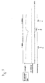
- Figures 2 and 3 show a first and a second embodiment of such a charge control, in which the charge takes place as a function of the state of charge or the time.
- the graph shows the state of charge of the electrical energy storage device 3, which can be determined, for example, based on the voltage provided by the energy storage, as a function of time.
- Below the diagram is also indicated whether the door drive is connected to the mains supply or not, ie whether the door drive in the first operating mode 6, in which the drive is disconnected from the mains supply and the electrical energy is provided by the electrical energy storage, or in the second operating mode 7, during which the door drive is connected to the mains supply 1.
- the charging control takes place while the charge as a function of state of charge. If the charge of the energy store falls below a switch-on threshold, the charge controller automatically switches from the first operating mode 6 into the second operating mode 7 by connecting the door drive according to the invention to the grid. As a result, the electrical energy storage is charged via the mains supply 1. If the electrical energy store is charged, the charge controller switches back to the first operating mode and disconnects the door drive according to the invention from the mains supply, so that the electrical energy is again made available by the electrical energy store, which thereby discharges again.
- Typical charging cycles thus consist of a long operating time in the first operating mode 6, which is followed by a short operating time in the second operating mode 7. Switches the controller regardless of the actual charge control in the second mode of operation, since the drive motor 10 is to be moved, the energy storage is also charged, thereby starting a new cycle.
- FIG. 3 now shows an alternative embodiment of the charging controller according to the invention, in which the charge takes place as a function of time. Since the maximum energy requirement in the inactive mode is known, the minimum time can be determined without recharging the energy storage. Will be the second during this time Operating mode, in which the energy storage is recharged, not already activated due to an operation of the drive motor 10, so the charging control switches to recharge in the second operating mode. This also makes it possible to ensure that the system voltage provided by the energy store does not fall below a minimum permissible system voltage.
- the power consumption of the door drive according to the invention over the period of one year can be reduced to approximately one tenth of the amount of energy usually required. This results in a significant energy cost savings and improved environmental protection.
- the integrated energy storage of the present invention can be optimally designed in its efficiency to the inactive mode, which is much more efficient during the inactive operating times than the power supply by a power supply.
- the energy storage device is then charged during the active operating cycles during which the drive motor 10 is moved and the door drive according to the invention is in any case connected to the mains supply. If this is insufficient, since the door drive is not activated often enough, the charging control according to the invention intervenes, which, if necessary, recharges the electrical energy store via the mains supply.
Landscapes
- Power-Operated Mechanisms For Wings (AREA)
- Control Of Ac Motors In General (AREA)
- Control Of Electric Motors In General (AREA)
Applications Claiming Priority (1)
| Application Number | Priority Date | Filing Date | Title |
|---|---|---|---|
| DE202007014555U DE202007014555U1 (de) | 2007-10-17 | 2007-10-17 | Torantrieb |
Publications (3)
| Publication Number | Publication Date |
|---|---|
| EP2050910A2 true EP2050910A2 (fr) | 2009-04-22 |
| EP2050910A3 EP2050910A3 (fr) | 2011-08-17 |
| EP2050910B1 EP2050910B1 (fr) | 2018-12-05 |
Family
ID=40076321
Family Applications (1)
| Application Number | Title | Priority Date | Filing Date |
|---|---|---|---|
| EP08014007.2A Active EP2050910B1 (fr) | 2007-10-17 | 2008-08-05 | Entraînement de porte |
Country Status (4)
| Country | Link |
|---|---|
| US (1) | US8493015B2 (fr) |
| EP (1) | EP2050910B1 (fr) |
| CN (1) | CN101413370A (fr) |
| DE (1) | DE202007014555U1 (fr) |
Cited By (2)
| Publication number | Priority date | Publication date | Assignee | Title |
|---|---|---|---|---|
| DE202009016303U1 (de) | 2009-12-01 | 2011-04-07 | Hörmann KG Antriebstechnik | Torantriebsvorrichtung |
| WO2011085761A3 (fr) * | 2010-01-18 | 2011-09-15 | Sommer Antriebs- Und Funktechnik Gmbh | Système d'entraînement pour une porte |
Families Citing this family (1)
| Publication number | Priority date | Publication date | Assignee | Title |
|---|---|---|---|---|
| DE202009014334U1 (de) * | 2009-10-23 | 2011-02-24 | Marantec Antriebs- Und Steuerungstechnik Gmbh & Co. Kg | Trafovorrichtung für Torantrieb und Torantrieb |
Citations (2)
| Publication number | Priority date | Publication date | Assignee | Title |
|---|---|---|---|---|
| EP0625626A1 (fr) | 1993-05-18 | 1994-11-23 | Marantec Antriebs- Und Steuerungstechnik Gmbh & Co., Produktions Kg | Equipement moteur électrique pour un vantail de porte |
| DE19641592A1 (de) | 1996-10-09 | 1998-04-16 | Geze Gmbh & Co | Automatischer Türantrieb |
Family Cites Families (15)
| Publication number | Priority date | Publication date | Assignee | Title |
|---|---|---|---|---|
| JP3465735B2 (ja) * | 1995-10-02 | 2003-11-10 | 株式会社大井製作所 | 車両用スライドドアの自動開閉制御装置 |
| CA2269001C (fr) * | 1998-04-21 | 2008-07-15 | The Chamberlain Group, Inc. | Controleur automatique de mecanisme de fermeture de porte |
| US6597138B2 (en) * | 2001-08-01 | 2003-07-22 | The Chamberlain Group, Inc. | Method and apparatus for controlling power supplied to a motor |
| US6670725B2 (en) * | 2001-11-13 | 2003-12-30 | The Chamberlain Group, Inc. | Power apparatus for intermittently powered equipment |
| JP4123153B2 (ja) * | 2002-02-27 | 2008-07-23 | 株式会社日立製作所 | 電源システム |
| US7755223B2 (en) * | 2002-08-23 | 2010-07-13 | The Chamberlain Group, Inc. | Movable barrier operator with energy management control and corresponding method |
| US6920718B2 (en) * | 2003-04-03 | 2005-07-26 | The Chamberlain Group, Inc. | Independent backup power supply for a security barrier |
| US7373756B2 (en) * | 2003-09-03 | 2008-05-20 | 4378580 Canada Inc. | Automatic portable door operating system |
| US7786619B2 (en) * | 2003-09-12 | 2010-08-31 | The Chamberlain Group, Inc. | DC power backup |
| CN2733709Y (zh) * | 2004-05-31 | 2005-10-12 | 四川长虹电器股份有限公司 | 开关电源装置 |
| DE102004037933B3 (de) * | 2004-08-04 | 2006-02-09 | Novoferm Tormatic Gmbh | Garagentorantrieb und Verfahren zum Betrieb eines solchen Garagentorantriebes |
| US7208897B2 (en) * | 2005-03-04 | 2007-04-24 | Linear Corporation | Motion control system for barrier drive |
| US7266962B2 (en) * | 2005-05-17 | 2007-09-11 | Whirlpool Corporation | Battery supplemented refrigerator and method for using same |
| US7382063B2 (en) * | 2005-05-24 | 2008-06-03 | Wayne-Dalton Corp. | Uninterruptible power source for a barrier operator and related methods |
| DE102005054693B4 (de) * | 2005-11-16 | 2014-09-18 | Georg Ludwig Kunz | Steuer- bzw. Regelsystem zum Antrieb eines Tores oder einer Türe |
-
2007
- 2007-10-17 DE DE202007014555U patent/DE202007014555U1/de not_active Expired - Lifetime
-
2008
- 2008-08-05 EP EP08014007.2A patent/EP2050910B1/fr active Active
- 2008-10-16 US US12/288,130 patent/US8493015B2/en active Active
- 2008-10-17 CN CNA2008101705409A patent/CN101413370A/zh active Pending
Patent Citations (2)
| Publication number | Priority date | Publication date | Assignee | Title |
|---|---|---|---|---|
| EP0625626A1 (fr) | 1993-05-18 | 1994-11-23 | Marantec Antriebs- Und Steuerungstechnik Gmbh & Co., Produktions Kg | Equipement moteur électrique pour un vantail de porte |
| DE19641592A1 (de) | 1996-10-09 | 1998-04-16 | Geze Gmbh & Co | Automatischer Türantrieb |
Cited By (4)
| Publication number | Priority date | Publication date | Assignee | Title |
|---|---|---|---|---|
| DE202009016303U1 (de) | 2009-12-01 | 2011-04-07 | Hörmann KG Antriebstechnik | Torantriebsvorrichtung |
| WO2011067087A1 (fr) | 2009-12-01 | 2011-06-09 | Hörmann KG Antriebstechnik | Dispositif d'entraînement de porte |
| DE112010004625B4 (de) * | 2009-12-01 | 2016-06-09 | Hörmann KG Antriebstechnik | Torantriebsvorrichtung |
| WO2011085761A3 (fr) * | 2010-01-18 | 2011-09-15 | Sommer Antriebs- Und Funktechnik Gmbh | Système d'entraînement pour une porte |
Also Published As
| Publication number | Publication date |
|---|---|
| DE202007014555U1 (de) | 2008-11-27 |
| EP2050910B1 (fr) | 2018-12-05 |
| US8493015B2 (en) | 2013-07-23 |
| CN101413370A (zh) | 2009-04-22 |
| US20090140675A1 (en) | 2009-06-04 |
| EP2050910A3 (fr) | 2011-08-17 |
Similar Documents
| Publication | Publication Date | Title |
|---|---|---|
| EP3479455B1 (fr) | Dispositif à accumulateurs d'énergie pour véhicule automobile | |
| DE69617026T2 (de) | Elektrisches netzteil mit gemischer anordnung von wechselrichter und wechselstrom-/gleichstromwandler | |
| EP1386389A1 (fr) | Dispositif pour alimenter en energie le reseau de bord multitension d'un vehicule | |
| DE102017207102A1 (de) | Stationärspeicher zum Zwischenspeichern von elektrischer Energie in einem elektrischen Versorgungsnetz sowie Betriebsverfahren und Nachrüstmodul für den Stationärspeicher | |
| EP2941363B1 (fr) | Alimentation en énergie électrique de moteurs électriques de propulsion d'un véhicule ferroviaire à l'aide d'une pluralité de moteurs à combustion | |
| DE102005014285A1 (de) | Vorrichtung und Verfahren zum Ladungsausgleich von in Reihe angeordneten einzelnen Zellen eines Energiespeichers | |
| EP3024130A1 (fr) | Dispositif convertisseur à courant continu | |
| DE102015011230A1 (de) | Energiespeichervorrichtung für ein elektrisches Wechselspannungsnetz | |
| AT510025A4 (de) | Antriebseinheit eines elektrofahrzeugs | |
| DE102014218738A1 (de) | Elektrisches System für ein elektrisch antreibbares Fahrzeug | |
| DE102017201657A1 (de) | Schaltungsanordnung, Bordnetz und Fortbewegungsmittel mit verbesserter Zwischenkreisaufladung | |
| EP2050910B1 (fr) | Entraînement de porte | |
| DE102012007158A1 (de) | Pulswechselrichter mit Stromzwischenkreis zum Fahren und Laden eines batteriebetriebenen Elektrofahrzeugs | |
| EP3811509B1 (fr) | Onduleur photovoltaïque et procédé de fonctionnement d'un tel inverseur photovoltaïque | |
| DE102020130539B4 (de) | Verfahren zum Betrieb eines Energieversorgungssystems, Energieversorgungssystem und Steuerungseinheit für ein Energieversorgungssystem | |
| DE102011076787A1 (de) | Energieversorgung | |
| WO2015039871A1 (fr) | Ensemble d'accumulation d'énergie, système d'accumulation d'énergie et procédé permettant de faire fonctionner un ensemble d'accumulation d'énergie | |
| DE102019202345B4 (de) | Fahrzeugbordnetz mit einem Akkumulator, einem Wechselspannungsanschluss und einem Gleichspannungsanschluss | |
| EP2385608B1 (fr) | Entraînement de meuble électro-motorisé doté d'un dispositif d'alimentation en énergie | |
| DE10057113B4 (de) | Energieversorgungsanordnung für Rauch- und Wärmeabzugsanlagen mit elektrischen Antrieben | |
| DE69626206T2 (de) | Verfahren und vorrichtung zur speisung elektrischer energie, und gerät mit einer solchen vorrichtung | |
| DE112010001155T5 (de) | Steuersystem für einen Einphasen-Induktionsmotor und Steuerverfahren für einen Einphasen-lnduktionsmotor | |
| EP2229719B1 (fr) | Circuiterie permettant de faire fonctionner un appareil ménager | |
| DE29613801U1 (de) | Kühlgerät | |
| DE202016009046U1 (de) | Aufladesystem zum Aufladen einer Hochvoltbatterie eines elektrisch angetriebenen Fahrzeugs |
Legal Events
| Date | Code | Title | Description |
|---|---|---|---|
| PUAI | Public reference made under article 153(3) epc to a published international application that has entered the european phase |
Free format text: ORIGINAL CODE: 0009012 |
|
| 17P | Request for examination filed |
Effective date: 20081103 |
|
| AK | Designated contracting states |
Kind code of ref document: A2 Designated state(s): AT BE BG CH CY CZ DE DK EE ES FI FR GB GR HR HU IE IS IT LI LT LU LV MC MT NL NO PL PT RO SE SI SK TR |
|
| AX | Request for extension of the european patent |
Extension state: AL BA MK RS |
|
| PUAL | Search report despatched |
Free format text: ORIGINAL CODE: 0009013 |
|
| AK | Designated contracting states |
Kind code of ref document: A3 Designated state(s): AT BE BG CH CY CZ DE DK EE ES FI FR GB GR HR HU IE IS IT LI LT LU LV MC MT NL NO PL PT RO SE SI SK TR |
|
| AX | Request for extension of the european patent |
Extension state: AL BA MK RS |
|
| RIC1 | Information provided on ipc code assigned before grant |
Ipc: E05F 15/10 20060101AFI20110711BHEP Ipc: E05F 15/16 20060101ALI20110711BHEP |
|
| AKX | Designation fees paid |
Designated state(s): DE ES FR GB IT |
|
| 17Q | First examination report despatched |
Effective date: 20130311 |
|
| REG | Reference to a national code |
Ref country code: DE Ref legal event code: R079 Ref document number: 502008016497 Country of ref document: DE Free format text: PREVIOUS MAIN CLASS: E05F0015100000 Ipc: E05F0015600000 |
|
| GRAP | Despatch of communication of intention to grant a patent |
Free format text: ORIGINAL CODE: EPIDOSNIGR1 |
|
| STAA | Information on the status of an ep patent application or granted ep patent |
Free format text: STATUS: GRANT OF PATENT IS INTENDED |
|
| RIC1 | Information provided on ipc code assigned before grant |
Ipc: E05F 15/60 20150101AFI20180524BHEP |
|
| INTG | Intention to grant announced |
Effective date: 20180625 |
|
| GRAS | Grant fee paid |
Free format text: ORIGINAL CODE: EPIDOSNIGR3 |
|
| GRAA | (expected) grant |
Free format text: ORIGINAL CODE: 0009210 |
|
| GRAA | (expected) grant |
Free format text: ORIGINAL CODE: 0009210 |
|
| STAA | Information on the status of an ep patent application or granted ep patent |
Free format text: STATUS: THE PATENT HAS BEEN GRANTED |
|
| AK | Designated contracting states |
Kind code of ref document: B1 Designated state(s): DE ES FR GB IT |
|
| REG | Reference to a national code |
Ref country code: GB Ref legal event code: FG4D Free format text: NOT ENGLISH |
|
| REG | Reference to a national code |
Ref country code: DE Ref legal event code: R096 Ref document number: 502008016497 Country of ref document: DE |
|
| PG25 | Lapsed in a contracting state [announced via postgrant information from national office to epo] |
Ref country code: ES Free format text: LAPSE BECAUSE OF FAILURE TO SUBMIT A TRANSLATION OF THE DESCRIPTION OR TO PAY THE FEE WITHIN THE PRESCRIBED TIME-LIMIT Effective date: 20181205 |
|
| REG | Reference to a national code |
Ref country code: DE Ref legal event code: R097 Ref document number: 502008016497 Country of ref document: DE |
|
| PLBE | No opposition filed within time limit |
Free format text: ORIGINAL CODE: 0009261 |
|
| STAA | Information on the status of an ep patent application or granted ep patent |
Free format text: STATUS: NO OPPOSITION FILED WITHIN TIME LIMIT |
|
| 26N | No opposition filed |
Effective date: 20190906 |
|
| PGFP | Annual fee paid to national office [announced via postgrant information from national office to epo] |
Ref country code: DE Payment date: 20250819 Year of fee payment: 18 |
|
| PGFP | Annual fee paid to national office [announced via postgrant information from national office to epo] |
Ref country code: IT Payment date: 20250829 Year of fee payment: 18 |
|
| PGFP | Annual fee paid to national office [announced via postgrant information from national office to epo] |
Ref country code: GB Payment date: 20250822 Year of fee payment: 18 |
|
| PGFP | Annual fee paid to national office [announced via postgrant information from national office to epo] |
Ref country code: FR Payment date: 20250827 Year of fee payment: 18 |