EP2050919A2 - Procédé et dispositif destiné à l'introduction d'un faisceau tubulaire constitué de tuyaux courts dans un canal de forage à l'aide d'une mesure de la force de traction - Google Patents
Procédé et dispositif destiné à l'introduction d'un faisceau tubulaire constitué de tuyaux courts dans un canal de forage à l'aide d'une mesure de la force de traction Download PDFInfo
- Publication number
- EP2050919A2 EP2050919A2 EP08166339A EP08166339A EP2050919A2 EP 2050919 A2 EP2050919 A2 EP 2050919A2 EP 08166339 A EP08166339 A EP 08166339A EP 08166339 A EP08166339 A EP 08166339A EP 2050919 A2 EP2050919 A2 EP 2050919A2
- Authority
- EP
- European Patent Office
- Prior art keywords
- pressure plate
- head
- pulling
- pipe
- diameter
- Prior art date
- Legal status (The legal status is an assumption and is not a legal conclusion. Google has not performed a legal analysis and makes no representation as to the accuracy of the status listed.)
- Granted
Links
Images


Classifications
-
- E—FIXED CONSTRUCTIONS
- E21—EARTH OR ROCK DRILLING; MINING
- E21B—EARTH OR ROCK DRILLING; OBTAINING OIL, GAS, WATER, SOLUBLE OR MELTABLE MATERIALS OR A SLURRY OF MINERALS FROM WELLS
- E21B7/00—Special methods or apparatus for drilling
- E21B7/20—Driving or forcing casings or pipes into boreholes, e.g. sinking; Simultaneously drilling and casing boreholes
-
- E—FIXED CONSTRUCTIONS
- E21—EARTH OR ROCK DRILLING; MINING
- E21B—EARTH OR ROCK DRILLING; OBTAINING OIL, GAS, WATER, SOLUBLE OR MELTABLE MATERIALS OR A SLURRY OF MINERALS FROM WELLS
- E21B47/00—Survey of boreholes or wells
- E21B47/007—Measuring stresses in a pipe string or casing
-
- E—FIXED CONSTRUCTIONS
- E21—EARTH OR ROCK DRILLING; MINING
- E21B—EARTH OR ROCK DRILLING; OBTAINING OIL, GAS, WATER, SOLUBLE OR MELTABLE MATERIALS OR A SLURRY OF MINERALS FROM WELLS
- E21B7/00—Special methods or apparatus for drilling
- E21B7/04—Directional drilling
- E21B7/046—Directional drilling horizontal drilling
-
- F—MECHANICAL ENGINEERING; LIGHTING; HEATING; WEAPONS; BLASTING
- F16—ENGINEERING ELEMENTS AND UNITS; GENERAL MEASURES FOR PRODUCING AND MAINTAINING EFFECTIVE FUNCTIONING OF MACHINES OR INSTALLATIONS; THERMAL INSULATION IN GENERAL
- F16L—PIPES; JOINTS OR FITTINGS FOR PIPES; SUPPORTS FOR PIPES, CABLES OR PROTECTIVE TUBING; MEANS FOR THERMAL INSULATION IN GENERAL
- F16L55/00—Devices or appurtenances for use in, or in connection with, pipes or pipe systems
- F16L55/16—Devices for covering leaks in pipes or hoses, e.g. hose-menders
- F16L55/162—Devices for covering leaks in pipes or hoses, e.g. hose-menders from inside the pipe
- F16L55/165—Devices for covering leaks in pipes or hoses, e.g. hose-menders from inside the pipe a pipe or flexible liner being inserted in the damaged section
- F16L55/1658—Devices for covering leaks in pipes or hoses, e.g. hose-menders from inside the pipe a pipe or flexible liner being inserted in the damaged section the old pipe being ruptured prior to insertion of a new pipe
Definitions
- the invention relates to a method and apparatus for drawing a tubing composed of short tubes in a drill channel, wherein the tubing with its one axial end connected to a pulling head, which is connected via a first tension member with a pulling device, and via a pipe string passing through the second Tension member is clamped between the tension head and a voltage applied to its other axial end pressure plate.
- a method of the type mentioned above is for example from the EP 860 638 A1 known.
- short tubes are understood to mean all new pipes that are connected to one another via push-in joints, regardless of their actual length.
- Short pipes are increasingly used in so-called burst lining and caliber bursting.
- burst lining the old pipe is first ruptured, the drill channel is enlarged by a widening head, and then the pipe string, whose outer diameter is slightly smaller than the widening head, is drawn into this drill channel.
- caliber bursting a calibration head and the new pipe are drawn into the old pipe without damaging or destroying it. The outside diameter The calibration head and the new pipe are slightly smaller than the inner diameter of the old pipe.
- Short pipes must be used where burst lining or caliber bursting occurs from shaft to shaft or from a shaft or from a small pit. Short pipes can also be laid with controllable horizontal drilling rigs if the target pit is too small for endless pipes.
- the tensile forces acting on the neural tubes have to be measured and recorded continuously during the drawing in of new pipes for pipeline rehabilitation. For this purpose, it is not sufficient to determine and hold the total tensile force to be applied by the pulling device. It is also necessary to determine and record the tensile forces acting exclusively on the neural tubes. From the DE 102 61 553 B4 For this purpose, it is known to connect an adapter, which can be connected to the incoming neuro-tube, to the expansion cone via a traction force measuring device. A similar solution will be found in the DE 100 19 663 C2 described. Both solutions are only suitable for drawing in endless tubes.
- the invention has for its object to provide a method of the type mentioned, in which the forces to be collected on the pipe string, which consists of a plurality of mated short tubes, in particular frictional forces can be reliably determined.
- This object is achieved in that the force exerted by the second tension member on the pressure plate force is measured when pulling the tubing.
- the measurement results are transmitted to a work terminal, recorded and displayed, this preferably being done in real time.
- the transmission can be done in a conventional manner wirelessly or by cable, which is performed for example by the pressure plate forth through the starting pit to the work terminal.
- a lubricant is introduced into the annular gap between the pipe string and the pipe channel wall depending on the measurement results in order to reduce the jacket friction, in particular with increasing length of pipe string.
- the total tensile force to be applied by the pulling device is measured and recorded.
- the path traveled by the pulling head can be measured so as to to present a force-displacement diagram and to identify particularly critical points in the drilling channel.
- the pulling device can, for example, work hydraulically.
- pressure has to be built up, it is measured by means of a pressure gauge and the measured data is sent to the working terminal.
- the determined data can be processed with the aid of a suitable program and the resulting calculated tensile force, so that when approaching a maximum permissible traction warning and / or reaching the maximum, the traction device is switched off manually or automatically. This process is logged for quality assurance.
- the distance covered by the traction head can be determined, for example, via a pulse counter, which is driven by the incoming first tension member, usually a rope or a chain.
- the condition of the old line is usually determined with the aid of a video camera pulled through the old line.
- This recorded in the line inspection video can be played simultaneously with the movement of the train head, wherein in a preferred embodiment of the invention, the position of the traction head and the forces occurring at the respective position are displayed. In this way, a very clear picture emerges of which forces arise and what causes they may have.
- the invention further relates to a device for drawing a tubing composed of short tubes into a drilling channel, comprising a pulling head, which is connectable on the one hand via a first tension member with a pulling device and on the other hand, the pipe string connectable is, as well as a second tension member which is connectable at its one end to the tension head and at its other end with a pressure plate which is intended to rest against the respective zugkopffernen end of the tubing.
- a force measuring device is arranged between the second tension member and the pressure plate.
- the second tension member is a pull rod which is composed of individual rod sections, the rod sections each having a continuous over its entire length external thread and being provided for connecting the rod sections with a corresponding internal thread provided connecting sleeves.
- the threaded portions of the current meter can be cut off according to the length of the short tubes used, which may possibly also be done on the site and allows a comfortable adaptation of the linkage sections to each short tubes to be laid.
- Such rods with an external thread preferably a coarse external thread with a large pitch, as used for example in tie rods, can be produced inexpensively.
- the pull rod is connectable within the tubing with centering means to hold the Glasgest brieflye in an axial position with respect to the tubing.
- centering means may comprise a centering body which can be screwed onto the respective threaded section.
- a connecting sleeve can be replaced by such a sleeve-shaped centering body, which comprises a plurality of radially projecting from this centering centering struts.
- the length the centering struts can be adjustable in order to be able to adapt the centering device to different pipe diameters.
- the centering can also be formed by an annular disc, whose inner diameter is slightly larger than the diameter of the Wergestfites and whose outer diameter is slightly smaller than the inner diameter of the tubing, so that the disc is simply pushed over the rod and used together with this in a short tube ,
- annular disc is only suitable for a specific pipe diameter.
- the pressure plate preferably has a radial slot so that it can be placed laterally on the respective rod section or can be deducted from this.
- the pulling head has at least one lubricant channel which can be connected to a sliding line and opens on the outer circumferential surface of the pulling head.
- the rod sections and the connecting sleeves may be hollow so that the interconnected rod sections form a sliding line connectable to the lubricant channel.
- the traction head has expediently a conical head part which serves for widening or caliber bursting, and at the large diameter end of the same attaching shaft part, which is used to connect the pipe string is determined.
- the shaft part can have a smaller outside diameter relative to the pipe diameter, so that the shaft part is inserted into the pipe end.
- the shaft part may also be a pipe socket with an inner diameter that is larger than the outer diameter of the pipe string, so that the pipe string is inserted with its end into the shaft part.
- a mark is attached to the outside of the pulling head, which corresponds to the position of the front end of the inserted into the shaft part pipe string. In this way, the tubing can be retracted exactly to the desired position in the target pit, without the pull head must be dismantled to determine the position can.
- FIG. 1 shows in a section containing the axis a generally designated 10 pipe string, which consists of individual short tubes 12 which are connected to each other via push-in sleeves and for this purpose at one end a sleeve 14 with respect to the other pipe diameter larger inner diameter and at its other end Plug-in part 16 with respect to the remaining pipe diameter smaller outer diameter.
- the existing of the individual nested short tubes 12 pipe string 10 has a constant outer diameter.
- the tubing string 10 is clamped between a generally designated 18 traction head and a pressure plate 20, wherein the traction head 18 and the pressure plate 20 are connected by a Switzerlandgestfite 22 with each other.
- the pulling head 18 has a frusto-conical head portion 24 which can be connected at its smaller diameter end, for example via a cable, a linkage, a chain 26 or the like with a tractor, not shown.
- a shaft portion 28 At its rear larger diameter end of the head portion 24 is connected to a shaft portion 28 whose outer diameter in the in FIG. 1 illustrated embodiment is selected so that the shaft part in the tubing string 10 and the first short tube 12 can be inserted.
- the shaft part is formed by a pipe socket, whose diameter is chosen so that the traction head 18 adjacent end of the tubing string 10 is inserted into the shaft part.
- the shaft part 28 carries on its outer circumference a sealing ring 30 (FIG. Fig. 1 and 3 ).
- the SwitzerlandgestInstitute consists of linkage sections 32 which are formed as tubes and on their outer circumference have a continuous thread 34 which in the FIGS. 1 only schematically indicated.
- the individual rod sections are screwed together by tubular connecting sleeves 36 which have an external thread 34 corresponding internal thread.
- Centering sleeves 38 which bear radially projecting centering struts 40 on their outer circumference, can replace the connecting sleeves.
- the struts 40 three of which are preferably provided at the same angular distance from each other, for example, in the threaded neck 42 may be screwed so that its radial length is adjustable to some extent.
- the pressure plate 20 has a central bore 44 through which the Glasgestfite 22 can pass freely, as the Figures 1 and 2 demonstrate. Furthermore, the pressure plate 20 is followed by a pipe socket 46, in accordance with in the embodiment FIG. 1 the pressure plate 20 facing the end of the tubing string 10 is inserted, while in the embodiment according to FIG. 2 the diameter of this nozzle 46 is selected so that the nozzle engages in the pipe end.
- an annular load cell 48 is attached, which is clamped by a clamping nut 50 against the pressure plate 20 and the pressure plate 20 presses against the end of the tubing 10.
- the clamping nut 50 can be tightened so that the short tubes 12 with a predetermined and can be pushed into each other by the load cell 48 ascertainable force.
- the pressure plate 20 has a radial slot 51, so that it can be slid onto the linkage section 32 from the side.
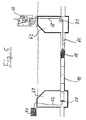
- FIG. 5 now shows a schematic section through a terrain with a start pit 60 and a target pit 62, which interrupt a drill channel 64, wherein in the lying between them piece of the drilling channel 64 of the traction head 18 hanging pipe string 10 is to be retracted.
- tractor 66 is used, which is known per se and will not be explained here. It pulls on a pull cable 68, which is deflected around a arranged in the target pit 62 roller 70, the tension head 18th From the pressure plate 20 and the in Figure 5 not shown load cell 48 is a cable 72, which leads to a workstation 74.
- the first linkage section 32 is cut to length so that after being screwed into a threaded neck 52 arranged on the head part 24 of the pulling head 18, it protrudes a little (about 100 mm) behind the first short tube 12, which is slipped onto the shaft part 28 of the pulling head 18.
- the pressure plate is attached to the protruding part of the linkage section 32.
- the load cell 48 is pushed from behind onto the linkage.
- the clamping nut 50 is screwed onto the linkage section and biased with a tool so strong that the Load cell indicates the force with which the short tubes are to be biased during the pipe intake (for example, 30kN).
- the clamping nut can also be tightened with a lightly driven tool to make the tube change as easy and fast as possible.
- the force gauge is then adjusted to zero and the first short tube is drawn into the drill channel or the old pipe.
- the load cell indicates the force with which the short pipe is drawn.
- This tensile force is essentially the frictional forces between the short tubes and the Bohrkanalwand or the wall of the old pipe. This tensile force must not exceed specified values. Traction is recorded or displayed and stored in a computer.
- the new short tube 12 is pulled into the previous pipe string.
- the socket joint between the short tubes 12 properly locks.
- the short tubes 12 are biased again with the prescribed force. The while The force actually acting on the tubing string on the tubing is again measured and recorded, as described above.
- the pulling head 18 has a plurality of radial lubricant channels 54 (FIG. Fig. 3 ), which open at the outer periphery of the head part 24 and communicate via a central channel 56 with the interior 58 of the tubular pull rod 22 in connection.
- the pull rod 22 can thus be used as a lubricant line to pump lubricant into the annular gap between the tubing string 10 and the Bohrkanalwand.
- the signals supplied by the load cell are transmitted via the cable 72 to the workstation 84, where they are processed, recorded and displayed.
- the total tractive force on the tractor 66 can also be determined, for example by the hydraulic pressure to be applied by the tractor being evaluated accordingly.
Landscapes
- Engineering & Computer Science (AREA)
- Geology (AREA)
- Life Sciences & Earth Sciences (AREA)
- Mining & Mineral Resources (AREA)
- Physics & Mathematics (AREA)
- Environmental & Geological Engineering (AREA)
- Fluid Mechanics (AREA)
- General Life Sciences & Earth Sciences (AREA)
- Geochemistry & Mineralogy (AREA)
- Mechanical Engineering (AREA)
- General Engineering & Computer Science (AREA)
- Geophysics (AREA)
- Earth Drilling (AREA)
Applications Claiming Priority (1)
| Application Number | Priority Date | Filing Date | Title |
|---|---|---|---|
| DE102007049605A DE102007049605B3 (de) | 2007-10-16 | 2007-10-16 | Verfahren und Vorrichtung zum Einziehen eines aus Kurzrohren zusammengesetzten Rohrstranges in einen Bohrkanal mit Zugkraftmessung |
Publications (3)
| Publication Number | Publication Date |
|---|---|
| EP2050919A2 true EP2050919A2 (fr) | 2009-04-22 |
| EP2050919A3 EP2050919A3 (fr) | 2010-06-23 |
| EP2050919B1 EP2050919B1 (fr) | 2011-06-22 |
Family
ID=40279062
Family Applications (1)
| Application Number | Title | Priority Date | Filing Date |
|---|---|---|---|
| EP08166339A Ceased EP2050919B1 (fr) | 2007-10-16 | 2008-10-10 | Procédé et dispositif destiné à l'introduction d'un faisceau tubulaire constitué de tuyaux courts dans un canal de forage à l'aide d'une mesure de la force de traction |
Country Status (2)
| Country | Link |
|---|---|
| EP (1) | EP2050919B1 (fr) |
| DE (1) | DE102007049605B3 (fr) |
Cited By (2)
| Publication number | Priority date | Publication date | Assignee | Title |
|---|---|---|---|---|
| CN108730677A (zh) * | 2018-07-13 | 2018-11-02 | 唐山市中宇科技发展有限公司 | 多功能无线遥控可视管道机器人爬行器 |
| CN112944034A (zh) * | 2021-01-26 | 2021-06-11 | 中交一公局第七工程有限公司 | 一种短管内衬非开挖管道修复方法 |
Families Citing this family (3)
| Publication number | Priority date | Publication date | Assignee | Title |
|---|---|---|---|---|
| DE102012103843A1 (de) * | 2012-05-02 | 2013-11-07 | Rbs Spezialmaschinen Gmbh | Vorrichtung und Verfahren zur grabenlosen Kanalsanierung |
| DE102019116522A1 (de) * | 2019-06-18 | 2020-12-24 | Bayerische Grabenlos GmbH | Rohrleitungswerkzeug sowie System und Verfahren zum grabenlosen Verlegen von Rohren |
| CN113048287B (zh) * | 2021-04-01 | 2022-07-12 | 中交第二航务工程局有限公司 | 承插式钢筋混凝土管道安装调整装置及使用方法 |
Citations (3)
| Publication number | Priority date | Publication date | Assignee | Title |
|---|---|---|---|---|
| EP0860638A1 (fr) | 1997-02-24 | 1998-08-26 | FlowTex Technologie GmbH | Dispositif et procédé de pose de tubes céramiques sans excavation |
| DE10019663C2 (de) | 2000-04-19 | 2002-02-14 | Huettner Beteiligungs Und Verm | Verfahren zur Erkennung der drohenden Überschreitung der zulässigen Belastungswerte von Kunststoff-Rohren |
| DE10261553B4 (de) | 2002-12-23 | 2005-11-17 | Bohrtec Gmbh | Verfahren und Vorrichtung zur Auswechslung erdverlegter Rohrleitungen (Stichwort: Tongeber) |
Family Cites Families (3)
| Publication number | Priority date | Publication date | Assignee | Title |
|---|---|---|---|---|
| WO2003004823A1 (fr) * | 2001-05-25 | 2003-01-16 | Tracto-Technik Gmbh | Dispositif de traction a cables pour l'insertion de tubes |
| DE10302194B3 (de) * | 2003-01-20 | 2004-08-19 | Tracto-Technik Gmbh | Vorrichtung und Verfahren zum Einziehen einer Leitung oder eines Bohrwerkzeugs in einen Kanal |
| US20060088384A1 (en) * | 2004-10-22 | 2006-04-27 | Putnam Samuel W | Stored energy coupling and pipe bursting apparatus |
-
2007
- 2007-10-16 DE DE102007049605A patent/DE102007049605B3/de not_active Expired - Fee Related
-
2008
- 2008-10-10 EP EP08166339A patent/EP2050919B1/fr not_active Ceased
Patent Citations (3)
| Publication number | Priority date | Publication date | Assignee | Title |
|---|---|---|---|---|
| EP0860638A1 (fr) | 1997-02-24 | 1998-08-26 | FlowTex Technologie GmbH | Dispositif et procédé de pose de tubes céramiques sans excavation |
| DE10019663C2 (de) | 2000-04-19 | 2002-02-14 | Huettner Beteiligungs Und Verm | Verfahren zur Erkennung der drohenden Überschreitung der zulässigen Belastungswerte von Kunststoff-Rohren |
| DE10261553B4 (de) | 2002-12-23 | 2005-11-17 | Bohrtec Gmbh | Verfahren und Vorrichtung zur Auswechslung erdverlegter Rohrleitungen (Stichwort: Tongeber) |
Cited By (4)
| Publication number | Priority date | Publication date | Assignee | Title |
|---|---|---|---|---|
| CN108730677A (zh) * | 2018-07-13 | 2018-11-02 | 唐山市中宇科技发展有限公司 | 多功能无线遥控可视管道机器人爬行器 |
| CN108730677B (zh) * | 2018-07-13 | 2024-03-26 | 唐山市中宇科技发展有限公司 | 多功能无线遥控可视管道机器人爬行器 |
| CN112944034A (zh) * | 2021-01-26 | 2021-06-11 | 中交一公局第七工程有限公司 | 一种短管内衬非开挖管道修复方法 |
| CN112944034B (zh) * | 2021-01-26 | 2022-11-01 | 中交一公局第七工程有限公司 | 一种短管内衬非开挖管道修复方法 |
Also Published As
| Publication number | Publication date |
|---|---|
| EP2050919A3 (fr) | 2010-06-23 |
| DE102007049605B3 (de) | 2009-04-30 |
| EP2050919B1 (fr) | 2011-06-22 |
Similar Documents
| Publication | Publication Date | Title |
|---|---|---|
| EP0808436B1 (fr) | Procede d'extraction d'un objet creux enterre | |
| DE3733463C1 (en) | Process and apparatus for exchanging pipes | |
| EP2050919B1 (fr) | Procédé et dispositif destiné à l'introduction d'un faisceau tubulaire constitué de tuyaux courts dans un canal de forage à l'aide d'une mesure de la force de traction | |
| DE202008001100U1 (de) | Rohraufweitvorrichtung | |
| DE102004036425B4 (de) | Vorrichtung und Verfahren zum Verbinden eines Rohrstrangs mit einem Bohr-, Aufweit- oder Einzugsgerät | |
| DE102010010603B4 (de) | Vorrichtung und Verfahren zur Herstellung konusförmiger Abschnitte an zylindrischen Rohren von Schraubfundamenten | |
| DE3415627A1 (de) | Rohrpruefgeraet | |
| EP2050920B1 (fr) | Procédé et dispositif destinés à l'introduction d'un faisceau tubulaire constitué de tuyaux courts dans un canal de forage | |
| EP1292419A1 (fr) | Procede de production d'un ecrou, taraud permettant la mise en oeuvre de ce procede et ecrou ainsi obtenu | |
| DE3719552C1 (en) | Connection piece | |
| EP2464908B1 (fr) | Raccord de tuyaux de gainage | |
| DE2602313C2 (de) | Verfahren zum Herausziehen eines langen, rohrförmigen Bauteils aus einer Paßbohrung und zum Nachformen dieser Paßbohrung sowie Räumwerkzeug hierzu | |
| DE102008006235A1 (de) | Ankerrohr und Verfahren zu dessen Herstellung | |
| AT509158B1 (de) | Vorrichtung zum entfernen oder zum auswechseln von kabeln | |
| DE3925504A1 (de) | Vorrichtung zum herausziehen eines in festmaterial eingebetteten rohres | |
| DE2650371A1 (de) | Kupplungsrohrteil aus kunststoff und verfahren zu seiner herstellung | |
| WO2011083085A1 (fr) | Procédé de restauration d'un ancien tuyau et système permettant de mettre en œuvre ce procédé | |
| DE69712396T2 (de) | Verfahren und Vorrichtung zum Herausziehen eines Rohrabschnittes aus einem Wärmetauscher und Anwendung des Verfahrens und der Vorrichtung | |
| EP3378577B1 (fr) | Dispositif de serrage hydraulique pour raccordement frictionnel démontable de deux composants | |
| DE102005026449B4 (de) | Rückhaltevorrichtung zum axialen Fixieren eines im Erdreich verlegten Leitungsrohres | |
| AT508617B1 (de) | Rohrverbindung sowie vorrichtung zur ausbildung einer rohrverbindung | |
| EP3045262B1 (fr) | Griffe d'ancrage pour tubes d'échangeurs thermiques | |
| DE19728905C2 (de) | Pilotrohrverbinder für erdreichverdrängende Pilotrohre | |
| AT217800B (de) | Anschlußeinrichtung für Rohre aus elastischem Werkstoff, insbesondere Kunststoff | |
| DE2343981C3 (de) | Ziehdorn zum Aushalsen von Rohren |
Legal Events
| Date | Code | Title | Description |
|---|---|---|---|
| PUAI | Public reference made under article 153(3) epc to a published international application that has entered the european phase |
Free format text: ORIGINAL CODE: 0009012 |
|
| AK | Designated contracting states |
Kind code of ref document: A2 Designated state(s): AT BE BG CH CY CZ DE DK EE ES FI FR GB GR HR HU IE IS IT LI LT LU LV MC MT NL NO PL PT RO SE SI SK TR |
|
| AX | Request for extension of the european patent |
Extension state: AL BA MK RS |
|
| PUAL | Search report despatched |
Free format text: ORIGINAL CODE: 0009013 |
|
| AK | Designated contracting states |
Kind code of ref document: A3 Designated state(s): AT BE BG CH CY CZ DE DK EE ES FI FR GB GR HR HU IE IS IT LI LT LU LV MC MT NL NO PL PT RO SE SI SK TR |
|
| AX | Request for extension of the european patent |
Extension state: AL BA MK RS |
|
| RIC1 | Information provided on ipc code assigned before grant |
Ipc: E21B 47/00 20060101ALI20100519BHEP Ipc: E21B 7/20 20060101ALI20100519BHEP Ipc: E21B 7/04 20060101AFI20090203BHEP Ipc: F16L 55/165 20060101ALI20100519BHEP |
|
| 17P | Request for examination filed |
Effective date: 20100812 |
|
| GRAP | Despatch of communication of intention to grant a patent |
Free format text: ORIGINAL CODE: EPIDOSNIGR1 |
|
| RIC1 | Information provided on ipc code assigned before grant |
Ipc: E21B 7/04 20060101AFI20100930BHEP Ipc: E21B 7/20 20060101ALI20100930BHEP Ipc: E21B 47/00 20060101ALI20100930BHEP Ipc: F16L 55/165 20060101ALI20100930BHEP |
|
| GRAS | Grant fee paid |
Free format text: ORIGINAL CODE: EPIDOSNIGR3 |
|
| AKX | Designation fees paid |
Designated state(s): CH FR GB LI |
|
| REG | Reference to a national code |
Ref country code: DE Ref legal event code: R108 Effective date: 20110201 Ref country code: DE Ref legal event code: 8566 |
|
| GRAA | (expected) grant |
Free format text: ORIGINAL CODE: 0009210 |
|
| AK | Designated contracting states |
Kind code of ref document: B1 Designated state(s): CH FR GB LI |
|
| REG | Reference to a national code |
Ref country code: GB Ref legal event code: FG4D Free format text: NOT ENGLISH |
|
| REG | Reference to a national code |
Ref country code: CH Ref legal event code: EP Ref country code: CH Ref legal event code: NV Representative=s name: SCHNEIDER FELDMANN AG PATENT- UND MARKENANWAELTE |
|
| PLBE | No opposition filed within time limit |
Free format text: ORIGINAL CODE: 0009261 |
|
| STAA | Information on the status of an ep patent application or granted ep patent |
Free format text: STATUS: NO OPPOSITION FILED WITHIN TIME LIMIT |
|
| 26N | No opposition filed |
Effective date: 20120323 |
|
| REG | Reference to a national code |
Ref country code: FR Ref legal event code: PLFP Year of fee payment: 8 |
|
| REG | Reference to a national code |
Ref country code: FR Ref legal event code: PLFP Year of fee payment: 9 |
|
| REG | Reference to a national code |
Ref country code: FR Ref legal event code: PLFP Year of fee payment: 10 |
|
| REG | Reference to a national code |
Ref country code: FR Ref legal event code: PLFP Year of fee payment: 11 |
|
| PGFP | Annual fee paid to national office [announced via postgrant information from national office to epo] |
Ref country code: CH Payment date: 20181025 Year of fee payment: 11 Ref country code: FR Payment date: 20181023 Year of fee payment: 11 Ref country code: GB Payment date: 20181025 Year of fee payment: 11 |
|
| REG | Reference to a national code |
Ref country code: CH Ref legal event code: PL |
|
| PG25 | Lapsed in a contracting state [announced via postgrant information from national office to epo] |
Ref country code: CH Free format text: LAPSE BECAUSE OF NON-PAYMENT OF DUE FEES Effective date: 20191031 Ref country code: LI Free format text: LAPSE BECAUSE OF NON-PAYMENT OF DUE FEES Effective date: 20191031 |
|
| GBPC | Gb: european patent ceased through non-payment of renewal fee |
Effective date: 20191010 |
|
| PG25 | Lapsed in a contracting state [announced via postgrant information from national office to epo] |
Ref country code: GB Free format text: LAPSE BECAUSE OF NON-PAYMENT OF DUE FEES Effective date: 20191010 Ref country code: FR Free format text: LAPSE BECAUSE OF NON-PAYMENT OF DUE FEES Effective date: 20191031 |