EP2050970A2 - Circuit hydraulique pour équipement lourd - Google Patents
Circuit hydraulique pour équipement lourd Download PDFInfo
- Publication number
- EP2050970A2 EP2050970A2 EP08017769A EP08017769A EP2050970A2 EP 2050970 A2 EP2050970 A2 EP 2050970A2 EP 08017769 A EP08017769 A EP 08017769A EP 08017769 A EP08017769 A EP 08017769A EP 2050970 A2 EP2050970 A2 EP 2050970A2
- Authority
- EP
- European Patent Office
- Prior art keywords
- hydraulic
- pressure
- flow path
- pilot
- valve
- Prior art date
- Legal status (The legal status is an assumption and is not a legal conclusion. Google has not performed a legal analysis and makes no representation as to the accuracy of the status listed.)
- Granted
Links
Images

Classifications
-
- F—MECHANICAL ENGINEERING; LIGHTING; HEATING; WEAPONS; BLASTING
- F15—FLUID-PRESSURE ACTUATORS; HYDRAULICS OR PNEUMATICS IN GENERAL
- F15B—SYSTEMS ACTING BY MEANS OF FLUIDS IN GENERAL; FLUID-PRESSURE ACTUATORS, e.g. SERVOMOTORS; DETAILS OF FLUID-PRESSURE SYSTEMS, NOT OTHERWISE PROVIDED FOR
- F15B11/00—Servomotor systems without provision for follow-up action; Circuits therefor
- F15B11/16—Servomotor systems without provision for follow-up action; Circuits therefor with two or more servomotors
- F15B11/17—Servomotor systems without provision for follow-up action; Circuits therefor with two or more servomotors using two or more pumps
-
- E—FIXED CONSTRUCTIONS
- E02—HYDRAULIC ENGINEERING; FOUNDATIONS; SOIL SHIFTING
- E02F—DREDGING; SOIL-SHIFTING
- E02F9/00—Component parts of dredgers or soil-shifting machines, not restricted to one of the kinds covered by groups E02F3/00 - E02F7/00
- E02F9/20—Drives; Control devices
- E02F9/22—Hydraulic or pneumatic drives
-
- E—FIXED CONSTRUCTIONS
- E02—HYDRAULIC ENGINEERING; FOUNDATIONS; SOIL SHIFTING
- E02F—DREDGING; SOIL-SHIFTING
- E02F9/00—Component parts of dredgers or soil-shifting machines, not restricted to one of the kinds covered by groups E02F3/00 - E02F7/00
- E02F9/20—Drives; Control devices
-
- E—FIXED CONSTRUCTIONS
- E02—HYDRAULIC ENGINEERING; FOUNDATIONS; SOIL SHIFTING
- E02F—DREDGING; SOIL-SHIFTING
- E02F9/00—Component parts of dredgers or soil-shifting machines, not restricted to one of the kinds covered by groups E02F3/00 - E02F7/00
- E02F9/20—Drives; Control devices
- E02F9/22—Hydraulic or pneumatic drives
- E02F9/2221—Control of flow rate; Load sensing arrangements
- E02F9/2225—Control of flow rate; Load sensing arrangements using pressure-compensating valves
- E02F9/2228—Control of flow rate; Load sensing arrangements using pressure-compensating valves including an electronic controller
-
- E—FIXED CONSTRUCTIONS
- E02—HYDRAULIC ENGINEERING; FOUNDATIONS; SOIL SHIFTING
- E02F—DREDGING; SOIL-SHIFTING
- E02F9/00—Component parts of dredgers or soil-shifting machines, not restricted to one of the kinds covered by groups E02F3/00 - E02F7/00
- E02F9/20—Drives; Control devices
- E02F9/22—Hydraulic or pneumatic drives
- E02F9/2221—Control of flow rate; Load sensing arrangements
- E02F9/2239—Control of flow rate; Load sensing arrangements using two or more pumps with cross-assistance
- E02F9/2242—Control of flow rate; Load sensing arrangements using two or more pumps with cross-assistance including an electronic controller
-
- E—FIXED CONSTRUCTIONS
- E02—HYDRAULIC ENGINEERING; FOUNDATIONS; SOIL SHIFTING
- E02F—DREDGING; SOIL-SHIFTING
- E02F9/00—Component parts of dredgers or soil-shifting machines, not restricted to one of the kinds covered by groups E02F3/00 - E02F7/00
- E02F9/20—Drives; Control devices
- E02F9/22—Hydraulic or pneumatic drives
- E02F9/2278—Hydraulic circuits
- E02F9/2292—Systems with two or more pumps
-
- E—FIXED CONSTRUCTIONS
- E02—HYDRAULIC ENGINEERING; FOUNDATIONS; SOIL SHIFTING
- E02F—DREDGING; SOIL-SHIFTING
- E02F9/00—Component parts of dredgers or soil-shifting machines, not restricted to one of the kinds covered by groups E02F3/00 - E02F7/00
- E02F9/20—Drives; Control devices
- E02F9/22—Hydraulic or pneumatic drives
- E02F9/2278—Hydraulic circuits
- E02F9/2296—Systems with a variable displacement pump
-
- F—MECHANICAL ENGINEERING; LIGHTING; HEATING; WEAPONS; BLASTING
- F15—FLUID-PRESSURE ACTUATORS; HYDRAULICS OR PNEUMATICS IN GENERAL
- F15B—SYSTEMS ACTING BY MEANS OF FLUIDS IN GENERAL; FLUID-PRESSURE ACTUATORS, e.g. SERVOMOTORS; DETAILS OF FLUID-PRESSURE SYSTEMS, NOT OTHERWISE PROVIDED FOR
- F15B21/00—Common features of fluid actuator systems; Fluid-pressure actuator systems or details thereof, not covered by any other group of this subclass
- F15B21/04—Special measures taken in connection with the properties of the fluid
- F15B21/042—Controlling the temperature of the fluid
- F15B21/0423—Cooling
-
- F—MECHANICAL ENGINEERING; LIGHTING; HEATING; WEAPONS; BLASTING
- F15—FLUID-PRESSURE ACTUATORS; HYDRAULICS OR PNEUMATICS IN GENERAL
- F15B—SYSTEMS ACTING BY MEANS OF FLUIDS IN GENERAL; FLUID-PRESSURE ACTUATORS, e.g. SERVOMOTORS; DETAILS OF FLUID-PRESSURE SYSTEMS, NOT OTHERWISE PROVIDED FOR
- F15B2211/00—Circuits for servomotor systems
- F15B2211/20—Fluid pressure source, e.g. accumulator or variable axial piston pump
- F15B2211/205—Systems with pumps
- F15B2211/2053—Type of pump
- F15B2211/20546—Type of pump variable capacity
-
- F—MECHANICAL ENGINEERING; LIGHTING; HEATING; WEAPONS; BLASTING
- F15—FLUID-PRESSURE ACTUATORS; HYDRAULICS OR PNEUMATICS IN GENERAL
- F15B—SYSTEMS ACTING BY MEANS OF FLUIDS IN GENERAL; FLUID-PRESSURE ACTUATORS, e.g. SERVOMOTORS; DETAILS OF FLUID-PRESSURE SYSTEMS, NOT OTHERWISE PROVIDED FOR
- F15B2211/00—Circuits for servomotor systems
- F15B2211/20—Fluid pressure source, e.g. accumulator or variable axial piston pump
- F15B2211/205—Systems with pumps
- F15B2211/20576—Systems with pumps with multiple pumps
-
- F—MECHANICAL ENGINEERING; LIGHTING; HEATING; WEAPONS; BLASTING
- F15—FLUID-PRESSURE ACTUATORS; HYDRAULICS OR PNEUMATICS IN GENERAL
- F15B—SYSTEMS ACTING BY MEANS OF FLUIDS IN GENERAL; FLUID-PRESSURE ACTUATORS, e.g. SERVOMOTORS; DETAILS OF FLUID-PRESSURE SYSTEMS, NOT OTHERWISE PROVIDED FOR
- F15B2211/00—Circuits for servomotor systems
- F15B2211/30—Directional control
- F15B2211/31—Directional control characterised by the positions of the valve element
- F15B2211/3105—Neutral or centre positions
- F15B2211/3116—Neutral or centre positions the pump port being open in the centre position, e.g. so-called open centre
-
- F—MECHANICAL ENGINEERING; LIGHTING; HEATING; WEAPONS; BLASTING
- F15—FLUID-PRESSURE ACTUATORS; HYDRAULICS OR PNEUMATICS IN GENERAL
- F15B—SYSTEMS ACTING BY MEANS OF FLUIDS IN GENERAL; FLUID-PRESSURE ACTUATORS, e.g. SERVOMOTORS; DETAILS OF FLUID-PRESSURE SYSTEMS, NOT OTHERWISE PROVIDED FOR
- F15B2211/00—Circuits for servomotor systems
- F15B2211/40—Flow control
- F15B2211/415—Flow control characterised by the connections of the flow control means in the circuit
- F15B2211/41509—Flow control characterised by the connections of the flow control means in the circuit being connected to a pressure source and a directional control valve
-
- F—MECHANICAL ENGINEERING; LIGHTING; HEATING; WEAPONS; BLASTING
- F15—FLUID-PRESSURE ACTUATORS; HYDRAULICS OR PNEUMATICS IN GENERAL
- F15B—SYSTEMS ACTING BY MEANS OF FLUIDS IN GENERAL; FLUID-PRESSURE ACTUATORS, e.g. SERVOMOTORS; DETAILS OF FLUID-PRESSURE SYSTEMS, NOT OTHERWISE PROVIDED FOR
- F15B2211/00—Circuits for servomotor systems
- F15B2211/40—Flow control
- F15B2211/42—Flow control characterised by the type of actuation
- F15B2211/428—Flow control characterised by the type of actuation actuated by fluid pressure
-
- F—MECHANICAL ENGINEERING; LIGHTING; HEATING; WEAPONS; BLASTING
- F15—FLUID-PRESSURE ACTUATORS; HYDRAULICS OR PNEUMATICS IN GENERAL
- F15B—SYSTEMS ACTING BY MEANS OF FLUIDS IN GENERAL; FLUID-PRESSURE ACTUATORS, e.g. SERVOMOTORS; DETAILS OF FLUID-PRESSURE SYSTEMS, NOT OTHERWISE PROVIDED FOR
- F15B2211/00—Circuits for servomotor systems
- F15B2211/40—Flow control
- F15B2211/45—Control of bleed-off flow, e.g. control of bypass flow to the return line
-
- F—MECHANICAL ENGINEERING; LIGHTING; HEATING; WEAPONS; BLASTING
- F15—FLUID-PRESSURE ACTUATORS; HYDRAULICS OR PNEUMATICS IN GENERAL
- F15B—SYSTEMS ACTING BY MEANS OF FLUIDS IN GENERAL; FLUID-PRESSURE ACTUATORS, e.g. SERVOMOTORS; DETAILS OF FLUID-PRESSURE SYSTEMS, NOT OTHERWISE PROVIDED FOR
- F15B2211/00—Circuits for servomotor systems
- F15B2211/50—Pressure control
- F15B2211/505—Pressure control characterised by the type of pressure control means
- F15B2211/50509—Pressure control characterised by the type of pressure control means the pressure control means controlling a pressure upstream of the pressure control means
-
- F—MECHANICAL ENGINEERING; LIGHTING; HEATING; WEAPONS; BLASTING
- F15—FLUID-PRESSURE ACTUATORS; HYDRAULICS OR PNEUMATICS IN GENERAL
- F15B—SYSTEMS ACTING BY MEANS OF FLUIDS IN GENERAL; FLUID-PRESSURE ACTUATORS, e.g. SERVOMOTORS; DETAILS OF FLUID-PRESSURE SYSTEMS, NOT OTHERWISE PROVIDED FOR
- F15B2211/00—Circuits for servomotor systems
- F15B2211/50—Pressure control
- F15B2211/575—Pilot pressure control
-
- F—MECHANICAL ENGINEERING; LIGHTING; HEATING; WEAPONS; BLASTING
- F15—FLUID-PRESSURE ACTUATORS; HYDRAULICS OR PNEUMATICS IN GENERAL
- F15B—SYSTEMS ACTING BY MEANS OF FLUIDS IN GENERAL; FLUID-PRESSURE ACTUATORS, e.g. SERVOMOTORS; DETAILS OF FLUID-PRESSURE SYSTEMS, NOT OTHERWISE PROVIDED FOR
- F15B2211/00—Circuits for servomotor systems
- F15B2211/60—Circuit components or control therefor
- F15B2211/63—Electronic controllers
- F15B2211/6303—Electronic controllers using input signals
- F15B2211/6343—Electronic controllers using input signals representing a temperature
-
- F—MECHANICAL ENGINEERING; LIGHTING; HEATING; WEAPONS; BLASTING
- F15—FLUID-PRESSURE ACTUATORS; HYDRAULICS OR PNEUMATICS IN GENERAL
- F15B—SYSTEMS ACTING BY MEANS OF FLUIDS IN GENERAL; FLUID-PRESSURE ACTUATORS, e.g. SERVOMOTORS; DETAILS OF FLUID-PRESSURE SYSTEMS, NOT OTHERWISE PROVIDED FOR
- F15B2211/00—Circuits for servomotor systems
- F15B2211/60—Circuit components or control therefor
- F15B2211/635—Circuits providing pilot pressure to pilot pressure-controlled fluid circuit elements
- F15B2211/6355—Circuits providing pilot pressure to pilot pressure-controlled fluid circuit elements having valve means
-
- F—MECHANICAL ENGINEERING; LIGHTING; HEATING; WEAPONS; BLASTING
- F15—FLUID-PRESSURE ACTUATORS; HYDRAULICS OR PNEUMATICS IN GENERAL
- F15B—SYSTEMS ACTING BY MEANS OF FLUIDS IN GENERAL; FLUID-PRESSURE ACTUATORS, e.g. SERVOMOTORS; DETAILS OF FLUID-PRESSURE SYSTEMS, NOT OTHERWISE PROVIDED FOR
- F15B2211/00—Circuits for servomotor systems
- F15B2211/60—Circuit components or control therefor
- F15B2211/66—Temperature control methods
-
- F—MECHANICAL ENGINEERING; LIGHTING; HEATING; WEAPONS; BLASTING
- F15—FLUID-PRESSURE ACTUATORS; HYDRAULICS OR PNEUMATICS IN GENERAL
- F15B—SYSTEMS ACTING BY MEANS OF FLUIDS IN GENERAL; FLUID-PRESSURE ACTUATORS, e.g. SERVOMOTORS; DETAILS OF FLUID-PRESSURE SYSTEMS, NOT OTHERWISE PROVIDED FOR
- F15B2211/00—Circuits for servomotor systems
- F15B2211/70—Output members, e.g. hydraulic motors or cylinders or control therefor
- F15B2211/71—Multiple output members, e.g. multiple hydraulic motors or cylinders
- F15B2211/7142—Multiple output members, e.g. multiple hydraulic motors or cylinders the output members being arranged in multiple groups
Definitions
- the present invention relates to a hydraulic circuit for heavy equipment which can utilize a part of flow rate of a hydraulic pump that drives a hydraulic pump for a cooling fan, as a hydraulic power source of remote control valve lever, and more particularly, to a hydraulic circuit for heavy equipment which can utilize a hydraulic fluid supplied from a hydraulic pump that drives a cooling fan, as a pilot signal pressure, without installing a constant displacement pilot pump for supplying the pilot signal pressure to a control valve that controls the hydraulic fluid to be supplied to a working device such as a boom.
- FIG. 1 shows a conventional hydraulic circuit for heavy equipment comprising first and second variable displacement hydraulic pumps 2 and 3 and third and fourth constant displacement hydraulic pumps 4 and 15 which are connected to an engine 1; a first control valve 5 installed in a flow path of the first variable displacement hydraulic pump 2 and controlling the hydraulic fluid to be supplied to an actuator that drives a working device, such as a boom, a bucket, a traveling device, or the like, by using a pilot signal pressure supplied from the fourth hydraulic pump 15; a second control valve 5a installed in a flow path of the second variable displacement hydraulic pump 3 and controlling a hydraulic fluid to be supplied to an actuator that drives a working drive, such as a swivel device, an arm, a traveling device, or the like, by using a pilot signal pressure supplied from the fourth hydraulic pump 15; a hydraulic motor 9 connected to the third constant displacement hydraulic pump 4; a cooling fan 10, connected to and rotated by the hydraulic motor 9, for discharging cooling wind towards an oil cooler 11 to lower a temperature of the hydraulic fluid drained to a hydraulic tank T through
- the pilot pressure generator 6 is connected to the fourth constant displacement hydraulic pump 15, and generates the pilot signal pressure to a driver at the switching.
- Reference numeral 6 denotes a relief valve installed in the flow path 18 of the fourth hydraulic pump 15 and draining the hydraulic fluid to the hydraulic tank T when a load exceeding the pressure set in the fourth hydraulic pump 15 generates.
- the working device such as a boom is driven by the hydraulic fluid supplied to the actuator from the first hydraulic pump 2
- the swivel device is driven by the hydraulic fluid supplied to the actuator (e.g. a swing motor) from the second hydraulic pump 3.
- the hydraulic motor 9 is driven by the hydraulic fluid supplied from the third hydraulic pump 4 along the drain path 17, and as the cooling fan 10 is driven by the hydraulic motor 9, the temperature of the hydraulic fluid passing through the oil cooler 11 installed in a return path 16 and returned to the hydraulic tank T.
- the intensity of cooling blast discharged from the cooling fan 10 to the oil cooler 11 is in proportion to the rotation velocity of the cooling fan 10, and as the rotation velocity of the cooling fan 10 is increased, the load pressure of the hydraulic motor 9 is proportionally increased.
- the load pressure of the hydraulic motor 9 is controlled by the electric relief valve 12. More specifically, if the load pressure of the hydraulic fluid supplied to the hydraulic motor 9 from the third hydraulic pump 4 exceeds the set pressure of the electric relief valve 12, the hydraulic fluid supplied from the third hydraulic pump 4 passes through the electric relief valve 12 and is drained to the hydraulic tank T. Consequently, the rotation velocity of the cooling fan 10 is controlled by the set pressure of the electric relief valve 12.
- the temperature of the hydraulic fluid is raised when the working device such as a boom is driven.
- the hydraulic fluid returned to the hydraulic tank T from the actuator passes through the oil cooler 11 installed in the return path, the temperature of the hydraulic fluid is lowered by the cool blast discharged from the cooling fan 10.
- the controller 14 varies the set pressure by transmitting the control signal to the electric relief valve 12 so as to maintain the temperature of the hydraulic fluid in a set value.
- the controller increases the set pressure of the electric relief valve 12 to increase the operation pressure which drives the hydraulic motor 9, thereby increasing the rotation velocity of the cooling fan 10 and thus improving the cooling capacity of the oil cooler 11.
- the fourth constant displacement hydraulic pump 15 discharges a constant amount of the hydraulic fluid in accordance with the rotation of the engine 1.
- the hydraulic fluid discharged from the fourth hydraulic pump 15 is momentarily used as the pilot signal pressure to switch the switch valves 5 and 5a when the pilot pressure generator 6 is switched.
- power loss (set pressure of relief valve 8) x (amount of hydraulic fluid to be drained to hydraulic tank T).
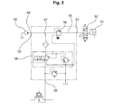
- FIG. 2 shows another conventional hydraulic circuit for the heavy equipment.
- the hydraulic circuit includes a hydraulic pump 50, an actuator 51 connected to the hydraulic pump 50, a solenoid valve 52 installed in a flow path 59 between the hydraulic pump 50 and the actuator 51 and controlling start, stop and direction change of the actuator 51, a sequence valve 56 installed in the first flow path 55 connecting a main inlet port 53 with a primary pressure outlet port 54, and a pressure reducing valve 58 installed in a secondary flow path 57 branched from the primary flow path 55 to constantly maintain the pressure of the secondary pressure output port 60.
- the present invention has been made to solve the above-mentioned problems occurring in the prior art while advantages achieved by the prior art are maintained intact.
- One object of the present invention is to provide a hydraulic circuit for heavy equipment capable of preventing power loss by removing a separate constant displacement pilot pump for supplying a pilot signal pressure to a control valve for a working device such as a boom, thereby making the construction thereof compact to reduce its cost.
- Another object of the present invention is to provide a hydraulic circuit for heavy equipment capable of preventing power loss by removing a sequence valve from a flow path between a hydraulic pump and a solenoid valve which controls a hydraulic fluid to be supplied to an actuator such as a boom cylinder.
- a hydraulic circuit for heavy equipment which includes first to third hydraulic pumps connected to an engine; a first control valve installed in a flow path of the first hydraulic pump, and controlling a hydraulic fluid to be supplied to an actuator that drives a working device when shifting; a second control valve installed in a flow path of the second hydraulic pump, and controlling hydraulic fluid to be supplied to an actuator that drives a working drive when shifting; a hydraulic motor connected to the third hydraulic pump; a cooling fan, connected to the hydraulic motor, for discharging cooling wind to an oil cooler which is installed in a return path of the first and second hydraulic pump to cool the hydraulic fluid to be returned to a hydraulic tank; a temperature sensor for detecting a temperature of the hydraulic fluid in the hydraulic tank; an electric relief valve, installed in a drain flow path of the third hydraulic pump, for controlling hydraulic pressure that drives the hydraulic motor to variably control a rotation velocity of the cooling fan; a controller for varying a set pressure of the electric relief valve in response to a detected signal from the temperature
- the hydraulic circuit further includes a pressure reducing valve, installed in the pilot flow path, for supplying the hydraulic fluid from the third hydraulic pump to the pilot pressure generator as a pilot signal pressure by a set pressure of a valve spring, the pressure reducing valve being shifted to drain the hydraulic fluid to the hydraulic tank when a load exceeding the set pressure of the valve spring is generated in the pilot pressure generator.
- a pressure reducing valve installed in the pilot flow path, for supplying the hydraulic fluid from the third hydraulic pump to the pilot pressure generator as a pilot signal pressure by a set pressure of a valve spring, the pressure reducing valve being shifted to drain the hydraulic fluid to the hydraulic tank when a load exceeding the set pressure of the valve spring is generated in the pilot pressure generator.
- the hydraulic circuit further includes a relief valve installed in the pilot flow path between the pressure reducing valve and the pilot pressure generator.
- a pressure of the relief valve is set to be higher than the set pressure of the pressure reducing valve, so that the hydraulic fluid of the drain path is prevented from being discharged to the hydraulic tank through the relief valve when a load pressure exceeding the set pressure of the relief valve is not generated in the drain flow path at a downstream of the pressure reducing valve.
- the hydraulic circuit can prevent power loss by removing a separate constant displacement pilot pump for supplying the pilot signal pressure to the control valve, thereby making the construction thereof compact to reduce its cost.
- the hydraulic circuit can prevent power loss by removing a sequence valve from the flow path between the hydraulic pump and the solenoid valve which controls a hydraulic fluid to be supplied to an actuator.
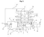
- FIG. 3 is a circuit diagram of a hydraulic circuit for heavy equipment according to an embodiment of the present invention.
- the hydraulic circuit according to the present invention includes first and second variable displacement hydraulic pumps 2 and 3 and a third constant displacement hydraulic pump 4 which are connected to an engine 1; a first control valve 5 installed in a flow path of the first variable displacement hydraulic pump 2 and controlling a hydraulic fluid to be supplied to an actuator that drives a working device, such as a boom, a bucket, a traveling device, or the like, by using a pilot signal pressure supplied from the third hydraulic pump 4; a second control valve 5a installed in a flow path of the second variable displacement hydraulic pump 3 and controlling a hydraulic fluid to be supplied to an actuator that drives a working drive, such as a swivel device, an arm, a traveling device, or the like, by using a pilot signal pressure supplied from the third hydraulic pump 4; a hydraulic motor 9 connected to the third constant displacement hydraulic pump 4; a cooling fan 10, connected to and rotated by the hydraulic motor 9, for discharging cooling wind towards an oil cooler 11 which is installed in a return path 16, to cool the hydraulic fluid to be drained to a hydraulic tank T;
- a pressure reducing valve 7 is installed in the pilot flow path 18 to supply the hydraulic fluid to the pilot pressure generator 6 from the third hydraulic pump 4 as a pilot signal pressure by a set pressure of a valve spring 7b.
- the pressure reducing valve 7 is switched to drain the hydraulic fluid to the hydraulic tank T.
- a relief valve 8 is installed in the pilot flow path 18 between the pressure reducing valve 7 and the pilot pressure generator 6.
- the pressure reducing valve 7 installed in the pilot flow path 18 to supply the hydraulic fluid to the pilot pressure generator 6 in accordance with the set pressure of the valve spring 7b or drain the hydraulic fluid of the drain path 19 to the hydraulic tank T, and the relief valve 8 preventing the hydraulic fluid from being discharged to the hydraulic tank T as the load pressure exceeding the set pressure is not generated in the drain path 19 is substantially equal to that shown in FIG. 1 , its detailed description will be omitted herein, in which the same parts are denoted by the same reference numerals.
- the hydraulic motor 9 is driven by the hydraulic fluid supplied from the third hydraulic pump 4 along the drain path 17, and as the cooling fan 10 is driven by the hydraulic motor 9, the cool blast is discharged towards the oil cooler 11.
- the temperature of the hydraulic fluid passing through the oil cooler 11 installed in the return path 16 and returned to the hydraulic tank T from the actuator can be lowered.
- a part of the hydraulic fluid discharged from the third hydraulic pump 4 is supplied to the pilot pressure generator 6 through the pressure reducing valve 7 installed in the pilot flow path 18 connected to the drain path 17.
- the first and second control valves 5 and 5a are maintained in a neutral position, and thus the hydraulic fluid discharged from the first and second hydraulic pumps 2 and 3 is returned to the hydraulic tank T via the first and second control valves 5 and 5a, the return path 16 and the oil cooler 11 in order.
- the hydraulic fluid discharged from the third hydraulic pump 4 is supplied to the first and second control valves 5 and 5a as a pilot signal pressure to shift the inner spools thereof. Therefore, the hydraulic fluid discharged from the first and second hydraulic pumps 2 and 3 is supplied to the actuator via the first and second control valves 5 and 5a to drive the working device such as a boom.
- the pressure of the hydraulic fluid to be supplied to the pilot pressure generator 6 from the third hydraulic pump 4 along the pilot flow path 18 can be maintained in a level of the set pressure of the valve spring 7b.
- the inner spool of the pressure reducing valve 7 is upwardly urged when viewing in the drawing to communicate the inlet flow path (i.e. the pilot flow path 18) with the outlet flow path (i.e. the drain path 19) in the pressure reducing valve 7 by the connection passage 7e of the pressure reducing valve 7, which is shown in FIG. 3 .
- the pressure of the drain path 19 is transmitted to the upper end of the pressure reducing valve 7 via a signal passage 7a, and thus the inner spool of the pressure reducing valve 7 is downwardly urged when viewing in the drawing to intercept the inlet flow path from the outlet flow path in the pressure reducing valve 7.
- the hydraulic fluid of the drain path 19 is drained to the hydraulic tank T via the passage 7c of the pressure reducing valve 7 which is communicated with a drain passage 7f.
- the pressure of the outlet flow passage (i.e. the drain path 19) of the pressure reducing valve 7 can be maintained in the level of the set pressure of the valve spring 7b in the pressure reducing valve 7.
Landscapes
- Engineering & Computer Science (AREA)
- General Engineering & Computer Science (AREA)
- Mining & Mineral Resources (AREA)
- Civil Engineering (AREA)
- Structural Engineering (AREA)
- Fluid Mechanics (AREA)
- Physics & Mathematics (AREA)
- Mechanical Engineering (AREA)
- Chemical & Material Sciences (AREA)
- Analytical Chemistry (AREA)
- Fluid-Pressure Circuits (AREA)
- Operation Control Of Excavators (AREA)
- Component Parts Of Construction Machinery (AREA)
Applications Claiming Priority (1)
| Application Number | Priority Date | Filing Date | Title |
|---|---|---|---|
| KR1020070104084A KR100915207B1 (ko) | 2007-10-16 | 2007-10-16 | 중장비용 유압회로 |
Publications (3)
| Publication Number | Publication Date |
|---|---|
| EP2050970A2 true EP2050970A2 (fr) | 2009-04-22 |
| EP2050970A3 EP2050970A3 (fr) | 2012-06-27 |
| EP2050970B1 EP2050970B1 (fr) | 2013-07-03 |
Family
ID=40258903
Family Applications (1)
| Application Number | Title | Priority Date | Filing Date |
|---|---|---|---|
| EP08017769.4A Not-in-force EP2050970B1 (fr) | 2007-10-16 | 2008-10-10 | Circuit hydraulique pour équipement lourd |
Country Status (5)
| Country | Link |
|---|---|
| US (1) | US8024926B2 (fr) |
| EP (1) | EP2050970B1 (fr) |
| JP (1) | JP2009097722A (fr) |
| KR (1) | KR100915207B1 (fr) |
| CN (1) | CN101413519B (fr) |
Cited By (10)
| Publication number | Priority date | Publication date | Assignee | Title |
|---|---|---|---|---|
| EP2399861A1 (fr) * | 2010-06-22 | 2011-12-28 | Linde Material Handling GmbH | Système d'entraînement hydrostatique |
| WO2012091942A1 (fr) * | 2010-12-29 | 2012-07-05 | Eaton Corporation | Agencement permettant d'augmenter le débit dans le carter en vue de refroidir des motopompes électriques à vitesse variable |
| WO2012166520A3 (fr) * | 2011-05-31 | 2013-02-14 | Caterpillar Inc. | Système de fluide hydraulique |
| CN103062162A (zh) * | 2012-12-27 | 2013-04-24 | 三一重工股份有限公司 | 一种液压油散热系统及工程机械 |
| EP2369067A3 (fr) * | 2009-12-29 | 2014-02-26 | Volvo Construction Equipment Holding Sweden AB | Système hydraulique de type à contrôle négatif |
| EP2613060A4 (fr) * | 2010-09-02 | 2014-12-03 | Volvo Constr Equip Ab | Circuit hydraulique pour équipement de construction |
| EP2889492A1 (fr) * | 2013-12-13 | 2015-07-01 | CNH Industrial Italia S.p.A. | Système de dérivation de refroidisseur de fluide pour un véhicule de travail agricole |
| CN104755712A (zh) * | 2012-10-16 | 2015-07-01 | 株式会社斗山 | Dpf的多级再生装置及再生方法 |
| CN105673599A (zh) * | 2016-03-15 | 2016-06-15 | 陕西理工学院 | 用于控制被焊件轴向长度的摩擦焊机液压系统及控制方法 |
| CN111188810A (zh) * | 2020-01-14 | 2020-05-22 | 三一汽车起重机械有限公司 | 一种液压油路及工程机械 |
Families Citing this family (23)
| Publication number | Priority date | Publication date | Assignee | Title |
|---|---|---|---|---|
| DE112009004511B4 (de) * | 2009-03-19 | 2018-07-12 | Toyota Jidosha Kabushiki Kaisha | STEUERUNGSVORRICHTUNG FüR EINE FAHRZEUGLEISTUNGSÜBERTRAGUNGSVORRICHTUNG |
| JP5606686B2 (ja) | 2009-04-14 | 2014-10-15 | ソニー株式会社 | 情報処理装置、情報処理方法及びプログラム |
| KR101032731B1 (ko) * | 2009-06-02 | 2011-05-06 | 볼보 컨스트럭션 이큅먼트 에이비 | 해머장치를 구비한 굴삭기용 유압시스템 |
| CN101936018A (zh) * | 2010-07-26 | 2011-01-05 | 徐工集团工程机械股份有限公司江苏徐州工程机械研究院 | 装载机电液比例控制系统 |
| CN102109037A (zh) * | 2011-01-21 | 2011-06-29 | 太原重工股份有限公司 | 一种液压挖掘机分动箱的冷却系统 |
| CN102155475A (zh) * | 2011-03-23 | 2011-08-17 | 徐州赫思曼电子有限公司 | 一种控制液压系统的装置及方法 |
| EP2694747B1 (fr) * | 2011-04-08 | 2018-03-14 | Volvo Construction Equipment AB | Agencement pour charger un accumulateur |
| WO2012153880A1 (fr) * | 2011-05-11 | 2012-11-15 | 볼보 컨스트럭션 이큅먼트 에이비 | Excavatrice hybride incluant un appareil d'arrêt rapide destiné à un organe de commande hybride |
| ITMI20111408A1 (it) * | 2011-07-27 | 2013-01-28 | Promau Srl | Apparato e metodo per il controllo elettroidraulico del parallelismo in una calandra per la lavorazione di manufatti in metallo |
| CN102425579A (zh) * | 2011-10-28 | 2012-04-25 | 中联重科股份有限公司 | 液压回转系统和液压空调系统布置结构及其工程机械设备 |
| US20150308079A1 (en) * | 2012-05-30 | 2015-10-29 | Volvo Construction Equipment Ab | A method for recovering energy and a hydraulic system |
| US9303662B2 (en) | 2012-12-27 | 2016-04-05 | Stac, Inc. | Pump fan control circuit and block for truck mountable hydraulic system |
| WO2014208787A1 (fr) * | 2013-06-26 | 2014-12-31 | 볼보 컨스트럭션 이큅먼트 에이비 | Dispositif de commande d'une vanne de commande d'un engin de chantier, son procédé de commande et procédé de commande du débit de refoulement d'une pompe hydraulique |
| CN103398050A (zh) * | 2013-08-12 | 2013-11-20 | 上海中联重科桩工机械有限公司 | 液压油温度控制系统及包含其的旋挖钻机、工程机械 |
| US9464580B2 (en) | 2014-01-02 | 2016-10-11 | Caterpillar Paving Products Inc. | Torque limit control |
| WO2016080562A1 (fr) * | 2014-11-17 | 2016-05-26 | 볼보 컨스트럭션 이큅먼트 에이비 | Dispositif de chauffage d'huile hydraulique d'équipement de construction et son procédé de commande |
| US9702118B2 (en) * | 2014-11-19 | 2017-07-11 | Caterpillar Inc. | Hydraulic regenerative and recovery parasitic mitigation system |
| CN104405704A (zh) * | 2014-11-28 | 2015-03-11 | 无锡诚石轴承有限公司 | 集中供油液压系统 |
| JP6333713B2 (ja) * | 2014-12-15 | 2018-05-30 | 株式会社Kcm | 油圧駆動システム |
| JP6630257B2 (ja) * | 2016-09-30 | 2020-01-15 | 日立建機株式会社 | 建設機械 |
| IT201800007591A1 (it) * | 2018-07-27 | 2020-01-27 | Atlantic Fluid Tech Srl | Dispositivo per Controllare un Attuatore |
| IT201900018701A1 (it) * | 2019-10-14 | 2021-04-14 | Ind Saleri Italo Spa | Assieme di gestione termica di un veicolo |
| CN112412930B (zh) * | 2020-11-18 | 2023-02-07 | 三一重机有限公司 | 散热系统及工程机械 |
Family Cites Families (11)
| Publication number | Priority date | Publication date | Assignee | Title |
|---|---|---|---|---|
| US3222865A (en) * | 1964-11-20 | 1965-12-14 | Case Co J I | Hydraulic apparatus and method |
| JPH06147205A (ja) * | 1992-11-04 | 1994-05-27 | Hitachi Constr Mach Co Ltd | 油圧作業機の油圧回路 |
| JP3897185B2 (ja) * | 1996-12-26 | 2007-03-22 | 株式会社小松製作所 | 冷却用ファンの駆動装置 |
| JP4107454B2 (ja) * | 1998-11-19 | 2008-06-25 | 株式会社小松製作所 | 油圧駆動冷却ファン装置 |
| US6195989B1 (en) * | 1999-05-04 | 2001-03-06 | Caterpillar Inc. | Power control system for a machine |
| JP2001165105A (ja) * | 1999-12-08 | 2001-06-19 | Shin Caterpillar Mitsubishi Ltd | 建設機械の駆動制御装置 |
| JP2001173602A (ja) * | 1999-12-15 | 2001-06-26 | Hitachi Constr Mach Co Ltd | 建設機械の熱交換装置 |
| KR100593103B1 (ko) * | 1999-12-29 | 2006-06-26 | 두산인프라코어 주식회사 | 건설중장비의 브레이크-파이롯-냉각팬모터 공급용 밸브 |
| JP4071696B2 (ja) * | 2003-09-24 | 2008-04-02 | 東芝機械株式会社 | 油圧ショベル用油圧システム |
| US7155907B2 (en) * | 2004-03-23 | 2007-01-02 | Yvon Clarence Desjardins | Electro-hydraulic fan drive cooling and steering system for vehicle |
| KR20070069688A (ko) * | 2005-12-28 | 2007-07-03 | 두산인프라코어 주식회사 | 건설중장비의 냉각팬 구동장치 |
-
2007
- 2007-10-16 KR KR1020070104084A patent/KR100915207B1/ko not_active Expired - Fee Related
-
2008
- 2008-10-07 US US12/246,515 patent/US8024926B2/en not_active Expired - Fee Related
- 2008-10-10 JP JP2008263528A patent/JP2009097722A/ja active Pending
- 2008-10-10 EP EP08017769.4A patent/EP2050970B1/fr not_active Not-in-force
- 2008-10-15 CN CN2008101696005A patent/CN101413519B/zh not_active Expired - Fee Related
Cited By (20)
| Publication number | Priority date | Publication date | Assignee | Title |
|---|---|---|---|---|
| EP2369067A3 (fr) * | 2009-12-29 | 2014-02-26 | Volvo Construction Equipment Holding Sweden AB | Système hydraulique de type à contrôle négatif |
| EP2399861A1 (fr) * | 2010-06-22 | 2011-12-28 | Linde Material Handling GmbH | Système d'entraînement hydrostatique |
| US9228599B2 (en) | 2010-09-02 | 2016-01-05 | Volvo Construction Equipment Ab | Hydraulic circuit for construction equipment |
| EP2613060A4 (fr) * | 2010-09-02 | 2014-12-03 | Volvo Constr Equip Ab | Circuit hydraulique pour équipement de construction |
| WO2012091942A1 (fr) * | 2010-12-29 | 2012-07-05 | Eaton Corporation | Agencement permettant d'augmenter le débit dans le carter en vue de refroidir des motopompes électriques à vitesse variable |
| CN103403361A (zh) * | 2010-12-29 | 2013-11-20 | 伊顿公司 | 用于冷却变速电动马达-泵的壳体流量增大装置 |
| US8876495B2 (en) | 2010-12-29 | 2014-11-04 | Eaton Corporation | Case flow augmenting arrangement for cooling variable speed electric motor-pumps |
| CN103403361B (zh) * | 2010-12-29 | 2015-11-25 | 伊顿公司 | 用于冷却变速电动马达-泵的壳体流量增大装置 |
| WO2012166520A3 (fr) * | 2011-05-31 | 2013-02-14 | Caterpillar Inc. | Système de fluide hydraulique |
| US8826654B2 (en) | 2011-05-31 | 2014-09-09 | Caterpillar Inc. | Hydraulic fluid system |
| CN104755712A (zh) * | 2012-10-16 | 2015-07-01 | 株式会社斗山 | Dpf的多级再生装置及再生方法 |
| EP2910746A4 (fr) * | 2012-10-16 | 2016-07-27 | Doosan Corp | Dispositif de régénération de filtre à particules diesel à plusieurs étages et son procédé de régénération |
| CN104755712B (zh) * | 2012-10-16 | 2017-09-15 | 株式会社斗山 | Dpf的多级再生装置及再生方法 |
| US10508581B2 (en) | 2012-10-16 | 2019-12-17 | Doosan Corporation | Multi-step regeneration device of DPF and regeneration method therefor |
| CN103062162A (zh) * | 2012-12-27 | 2013-04-24 | 三一重工股份有限公司 | 一种液压油散热系统及工程机械 |
| EP2889492A1 (fr) * | 2013-12-13 | 2015-07-01 | CNH Industrial Italia S.p.A. | Système de dérivation de refroidisseur de fluide pour un véhicule de travail agricole |
| US10260824B2 (en) | 2013-12-13 | 2019-04-16 | Cnh Industrial America Llc | Fluid cooler bypass system for an agricultural work vehicle |
| CN105673599A (zh) * | 2016-03-15 | 2016-06-15 | 陕西理工学院 | 用于控制被焊件轴向长度的摩擦焊机液压系统及控制方法 |
| CN105673599B (zh) * | 2016-03-15 | 2017-02-08 | 陕西理工学院 | 用于控制被焊件轴向长度的摩擦焊机液压系统及控制方法 |
| CN111188810A (zh) * | 2020-01-14 | 2020-05-22 | 三一汽车起重机械有限公司 | 一种液压油路及工程机械 |
Also Published As
| Publication number | Publication date |
|---|---|
| US20090094973A1 (en) | 2009-04-16 |
| JP2009097722A (ja) | 2009-05-07 |
| EP2050970A3 (fr) | 2012-06-27 |
| EP2050970B1 (fr) | 2013-07-03 |
| US8024926B2 (en) | 2011-09-27 |
| CN101413519A (zh) | 2009-04-22 |
| KR20090038664A (ko) | 2009-04-21 |
| KR100915207B1 (ko) | 2009-09-02 |
| CN101413519B (zh) | 2013-06-12 |
Similar Documents
| Publication | Publication Date | Title |
|---|---|---|
| US8024926B2 (en) | Hydraulic circuit for heavy equipment | |
| US8301346B2 (en) | Traveling system for construction equipment | |
| US5873245A (en) | Hydraulic drive system | |
| EP2341193B1 (fr) | Système hydraulique de type à contrôle négatif | |
| US9228599B2 (en) | Hydraulic circuit for construction equipment | |
| CN102265041B (zh) | 工程机械的液压泵控制装置 | |
| CN104379945B (zh) | 建筑机械的控制系统 | |
| US20100303643A1 (en) | Fan Drive System | |
| EP1830066B1 (fr) | Appareil de contrôle hydraulique de machine de travail | |
| JP2013124763A (ja) | 作業機械の油圧駆動装置 | |
| JP4446822B2 (ja) | 作業車両の油圧駆動装置 | |
| KR102156447B1 (ko) | 건설기계의 유압시스템 | |
| EP1764515B1 (fr) | Système hydraulique pour engins de construction | |
| JP2017101791A (ja) | 油圧モータ制御装置 | |
| US7591214B2 (en) | Driving motor controlling device of construction machine | |
| JP4969541B2 (ja) | 作業機械の油圧制御装置 | |
| KR100640538B1 (ko) | 굴삭기 유압펌프 유량제어장치 | |
| KR20110074388A (ko) | 건설기계의 유압회로 | |
| JP2001254681A (ja) | 可変容量ポンプの入力トルク制御回路 | |
| JP2007333017A (ja) | 建設機械の省エネ装置 | |
| JP2008002505A (ja) | 建設機械の省エネ装置 | |
| KR100762078B1 (ko) | 굴삭기 유압펌프의 유량제어장치 | |
| KR20040080177A (ko) | 릴리프밸브를 이용한 유압펌프의 유량 제어장치 | |
| JP2005299931A (ja) | 建設機械の油圧制御装置 | |
| JP2009097579A (ja) | 建設機械の油圧回路 |
Legal Events
| Date | Code | Title | Description |
|---|---|---|---|
| PUAI | Public reference made under article 153(3) epc to a published international application that has entered the european phase |
Free format text: ORIGINAL CODE: 0009012 |
|
| AK | Designated contracting states |
Kind code of ref document: A2 Designated state(s): AT BE BG CH CY CZ DE DK EE ES FI FR GB GR HR HU IE IS IT LI LT LU LV MC MT NL NO PL PT RO SE SI SK TR |
|
| AX | Request for extension of the european patent |
Extension state: AL BA MK RS |
|
| PUAL | Search report despatched |
Free format text: ORIGINAL CODE: 0009013 |
|
| AK | Designated contracting states |
Kind code of ref document: A3 Designated state(s): AT BE BG CH CY CZ DE DK EE ES FI FR GB GR HR HU IE IS IT LI LT LU LV MC MT NL NO PL PT RO SE SI SK TR |
|
| AX | Request for extension of the european patent |
Extension state: AL BA MK RS |
|
| RIC1 | Information provided on ipc code assigned before grant |
Ipc: F15B 11/17 20060101AFI20120518BHEP Ipc: F01P 7/04 20060101ALI20120518BHEP Ipc: F15B 21/04 20060101ALI20120518BHEP Ipc: E02F 9/22 20060101ALI20120518BHEP |
|
| 17P | Request for examination filed |
Effective date: 20121212 |
|
| GRAP | Despatch of communication of intention to grant a patent |
Free format text: ORIGINAL CODE: EPIDOSNIGR1 |
|
| AKX | Designation fees paid |
Designated state(s): DE FR GB IT |
|
| GRAS | Grant fee paid |
Free format text: ORIGINAL CODE: EPIDOSNIGR3 |
|
| GRAA | (expected) grant |
Free format text: ORIGINAL CODE: 0009210 |
|
| AK | Designated contracting states |
Kind code of ref document: B1 Designated state(s): DE FR GB IT |
|
| REG | Reference to a national code |
Ref country code: GB Ref legal event code: FG4D |
|
| REG | Reference to a national code |
Ref country code: DE Ref legal event code: R096 Ref document number: 602008025665 Country of ref document: DE Effective date: 20130829 |
|
| PLBE | No opposition filed within time limit |
Free format text: ORIGINAL CODE: 0009261 |
|
| STAA | Information on the status of an ep patent application or granted ep patent |
Free format text: STATUS: NO OPPOSITION FILED WITHIN TIME LIMIT |
|
| 26N | No opposition filed |
Effective date: 20140404 |
|
| REG | Reference to a national code |
Ref country code: DE Ref legal event code: R097 Ref document number: 602008025665 Country of ref document: DE Effective date: 20140404 |
|
| REG | Reference to a national code |
Ref country code: FR Ref legal event code: PLFP Year of fee payment: 8 |
|
| REG | Reference to a national code |
Ref country code: FR Ref legal event code: PLFP Year of fee payment: 9 |
|
| PGFP | Annual fee paid to national office [announced via postgrant information from national office to epo] |
Ref country code: FR Payment date: 20170223 Year of fee payment: 9 Ref country code: DE Payment date: 20170221 Year of fee payment: 9 |
|
| PGFP | Annual fee paid to national office [announced via postgrant information from national office to epo] |
Ref country code: GB Payment date: 20170222 Year of fee payment: 9 |
|
| PGFP | Annual fee paid to national office [announced via postgrant information from national office to epo] |
Ref country code: IT Payment date: 20170316 Year of fee payment: 9 |
|
| REG | Reference to a national code |
Ref country code: DE Ref legal event code: R119 Ref document number: 602008025665 Country of ref document: DE |
|
| GBPC | Gb: european patent ceased through non-payment of renewal fee |
Effective date: 20171010 |
|
| REG | Reference to a national code |
Ref country code: FR Ref legal event code: ST Effective date: 20180629 |
|
| PG25 | Lapsed in a contracting state [announced via postgrant information from national office to epo] |
Ref country code: GB Free format text: LAPSE BECAUSE OF NON-PAYMENT OF DUE FEES Effective date: 20171010 Ref country code: DE Free format text: LAPSE BECAUSE OF NON-PAYMENT OF DUE FEES Effective date: 20180501 |
|
| PG25 | Lapsed in a contracting state [announced via postgrant information from national office to epo] |
Ref country code: FR Free format text: LAPSE BECAUSE OF NON-PAYMENT OF DUE FEES Effective date: 20171031 |
|
| PG25 | Lapsed in a contracting state [announced via postgrant information from national office to epo] |
Ref country code: IT Free format text: LAPSE BECAUSE OF NON-PAYMENT OF DUE FEES Effective date: 20171010 |