EP2050980B1 - Fixation de garniture d'un frein à disques et garniture de frein - Google Patents
Fixation de garniture d'un frein à disques et garniture de frein Download PDFInfo
- Publication number
- EP2050980B1 EP2050980B1 EP08017611.8A EP08017611A EP2050980B1 EP 2050980 B1 EP2050980 B1 EP 2050980B1 EP 08017611 A EP08017611 A EP 08017611A EP 2050980 B1 EP2050980 B1 EP 2050980B1
- Authority
- EP
- European Patent Office
- Prior art keywords
- pad
- brake
- spring
- carrier plate
- brake pad
- Prior art date
- Legal status (The legal status is an assumption and is not a legal conclusion. Google has not performed a legal analysis and makes no representation as to the accuracy of the status listed.)
- Active
Links
Images




Classifications
-
- F—MECHANICAL ENGINEERING; LIGHTING; HEATING; WEAPONS; BLASTING
- F16—ENGINEERING ELEMENTS AND UNITS; GENERAL MEASURES FOR PRODUCING AND MAINTAINING EFFECTIVE FUNCTIONING OF MACHINES OR INSTALLATIONS; THERMAL INSULATION IN GENERAL
- F16D—COUPLINGS FOR TRANSMITTING ROTATION; CLUTCHES; BRAKES
- F16D65/00—Parts or details
- F16D65/02—Braking members; Mounting thereof
- F16D65/04—Bands, shoes or pads; Pivots or supporting members therefor
- F16D65/092—Bands, shoes or pads; Pivots or supporting members therefor for axially-engaging brakes, e.g. disc brakes
- F16D65/095—Pivots or supporting members therefor
- F16D65/097—Resilient means interposed between pads and supporting members or other brake parts
- F16D65/0973—Resilient means interposed between pads and supporting members or other brake parts not subjected to brake forces
- F16D65/0974—Resilient means interposed between pads and supporting members or other brake parts not subjected to brake forces acting on or in the vicinity of the pad rim in a direction substantially transverse to the brake disc axis
- F16D65/0975—Springs made from wire
-
- F—MECHANICAL ENGINEERING; LIGHTING; HEATING; WEAPONS; BLASTING
- F16—ENGINEERING ELEMENTS AND UNITS; GENERAL MEASURES FOR PRODUCING AND MAINTAINING EFFECTIVE FUNCTIONING OF MACHINES OR INSTALLATIONS; THERMAL INSULATION IN GENERAL
- F16D—COUPLINGS FOR TRANSMITTING ROTATION; CLUTCHES; BRAKES
- F16D65/00—Parts or details
- F16D65/02—Braking members; Mounting thereof
- F16D65/04—Bands, shoes or pads; Pivots or supporting members therefor
- F16D65/092—Bands, shoes or pads; Pivots or supporting members therefor for axially-engaging brakes, e.g. disc brakes
- F16D65/095—Pivots or supporting members therefor
- F16D65/097—Resilient means interposed between pads and supporting members or other brake parts
- F16D65/0973—Resilient means interposed between pads and supporting members or other brake parts not subjected to brake forces
- F16D65/0974—Resilient means interposed between pads and supporting members or other brake parts not subjected to brake forces acting on or in the vicinity of the pad rim in a direction substantially transverse to the brake disc axis
- F16D65/0975—Springs made from wire
- F16D65/0976—Springs made from wire acting on one pad only
Definitions
- the invention relates to a brake pad holder of a disc brake according to the preamble of claim 1 and a brake pad for a disc brake.
- Such a brake pad holder is from the DE 40 20 287 A1 known.
- the construction disclosed therein has proven itself in practice, especially under the often harsh operating conditions to which disc brakes in commercial vehicles are subjected.
- these are each provided with a pad retaining spring, which are designed as a leaf spring and in the upper, a mounting opening of the caliper facing edge region are secured to the brake pad, that they from a transversely to, ie in the axial direction of the brake disc extending pad retainer under bias are set, wherein the pad retaining bracket is fixed in two opposite, the mounting opening bounding areas of the caliper.
- the mounting of the brake pads under spring tension serves both a tolerance compensation as a reduction or a prevention of the emergence of Rattling noises, as they would otherwise occur while driving the vehicle.
- the known brake pad holder is designed so that the respective pad retaining spring is attached to retaining tabs of the associated brake pad, the corresponding recesses of the pad retaining spring pass, wherein this is held in the radial direction in such a way that an automatic release in a relaxed or partially relaxed position is excluded.
- the pad retaining spring Since only two attachment points are provided for fixing the pad retaining spring, which are arranged offset to each other, the pad retaining spring is also used as a handle and thereby centrally taken so that it acts in the sense of a two-sided clamped carrier, with the tendency of a correspondingly strong deflection. This may possibly change the spring characteristic of the pad retaining spring, which then adversely affects their function.
- An impairment of the functionality of the pad retaining springs may result in addition by their leaf shape, since the pad retaining springs abut with their broad side of the pad retaining bracket, resulting in a brake-related displacement of the brake pads to a correspondingly high frictional resistance.
- a brake pad having a pad retaining spring which is secured by a wrapping to a protruding projection, two free legs of the pad retaining spring being intended to rest on a caliper in the installed position.
- the invention has for its object to further develop a brake pad holder of the generic type or a brake pad so that a more cost-effective production is possible, the service life of the pad retainers in particular increased and the reliability of the disc brake is improved.
- the production of the new pad retaining springs is cheaper than those of the previously used, including in particular a simplified attachment counts on each associated brake pad.
- the production of the new pad retaining springs is cheaper than those of the previously used, including in particular a simplified attachment counts on each associated brake pad.
- the improved reliability of the brake pad holder is to be emphasized as a particular advantage of the invention, which results from a reduced heat application of the pad retaining springs.
- the pad retaining spring is provided at both ends with angled legs, which are each guided in an associated recess of the pad carrier plate, wherein at least one recess in the sense of a slot is formed, so that a longitudinal extension at a deflection of the pad retaining spring easily possible.
- the angled legs are extending in the axial direction of the brake disc and held by means of suitable securing means on the lining carrier plate.
- the recesses for the implementation of the angled legs in the lining carrier plate are provided in tabs formed thereon, in their Thickness are dimensioned so that the guided legs of the pad retaining spring abut in sufficient length on the wall of the recess, wherein the mutually associated dimensions of the cross section of the respective leg on the one hand and the width or the diameter of the recess on the other hand with little play correspond to each other.
- the spring characteristic of the pad retaining spring can be influenced.
- the recesses may be formed in their course as long holes horizontally, convexly, corresponding to the convex course of the upper edge of the lining carrier plate or in the form of curves rising or falling outward.
- the pad retaining spring associated edge region of the lining carrier plate on which the pad retaining spring is attached by appropriate shaping, for example in the sense of a ramp, a hump or a dent influence on the spring characteristic of the pad support spring supporting it.
- the said leadership of the legs of the pad retaining spring in the respective associated recess of the lining carrier plate also prevents tilting of the pad retaining spring as their inventively provided bulge in the middle region, which is formed transversely to the radially resilient deflection and abuts the pad retaining clip.
- This bulge which advantageously extends from the friction lining facing back of the lining carrier plate to the friction lining, forms by their imaginary surface enclosing contour a support by means of which the lining retaining spring in a sufficient manner secured against tipping on the lining retaining bracket is supported.
- the pad retaining spring associated edge region of the lining carrier plate with two spaced apart humps, between which the bulge of the pad retaining spring is positioned.
- integrally formed on the lining carrier plate ramp may be provided on the bumps, where then the lining holding spring is partially supported, said ramps to the back of the lining carrier plate fall off.
- the pad retaining spring is not made of a spring wire, but, as before, from a leaf spring, in which case this leaf spring has corresponding recesses, which are penetrated by the humps.
- the pad spring consisting of spring wire is permanently connected to the lining carrier plate.
- This can be done by an end-mounted disc, which is connected by positive engagement, such as crimping or other deformation or by material bond such as welding such that the pad retaining spring can only be solved by destroying this connection.
- a reliability of the brake lining holder disparaging multiple use of the pad retaining spring is effectively prevented.
- the pad retainer can also be designed in the connection area with the brake caliper so that only the intended, ie, the suitable pad retaining bracket can be used.
- the lining retaining clip may be shaped on the end so that it can be inserted into a receiving opening of the caliper exclusively in this embodiment.
- a pocket is formed for receiving the pad retaining bracket in the caliper, which has a rectangular cross-section and is made by means of a core during casting of the existing brake caliper.
- the core can be constructed with a removable insert, whereby the shape of the bag and thus the quasi-coding key is produced cost-neutral.
- the cross-sectional geometry of the bag as well as the pad retaining clip adapted thereto can in principle be of any desired design.
- a bevel and a radius are given, which are formed on one or two sides.
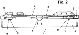
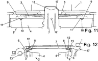
- FIG. 1 As well as in a partial section in the FIG. 11 is a brake pad holder of a disc brake, in particular for commercial vehicles shown, for holding two brake pads 2, the spring-loaded each mounted in a lining shaft 5 of a caliper 1 and in the case of braking on both sides of a brake disc, not shown are pressed.
- Each brake pad 2 consists of a lining carrier plate 3 and a friction lining 4 mounted thereon and in contact with the brake disk.
- each brake pad 2 spring-loaded in the lining shaft 5
- a pad retaining spring 6 which is secured to the corresponding pad carrier plate 3 and which is biased against a lining retaining bracket 7, which is fixed with both ends on the brake caliper 1 and spans a mounting opening of the caliper 1 transversely to the longitudinal extent of the brake pad 2.
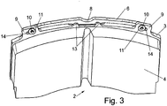
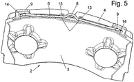
- the pad retaining spring 6 is made of a spring wire and formed in the middle region transverse to the resilient deflection to a bulge 8, against which the pad retaining bracket 7.
- the formed upper side of the pad retaining spring 6 runs parallel to the adjoining pressure side of the pad retaining clip 7, so that the pad retaining spring 6 rests over a larger support area.
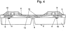
- lining retaining spring 6 At both ends of the lining retaining spring 6 is provided with an angled leg 10 which is held in each case in a tab 9 of the lining carrier plate 3, which are integrally formed on the lining support bracket 7 facing edge side of the lining carrier plate 3.
- the pad retaining spring 6 is mounted longitudinally displaceable in the tabs 9, so that a change in length of the imaginary tendon when compressing the pad retaining spring 6 is easily compensated.
- Both tabs 9 may be provided with slots 14, as shown in the Figures 3 . 5 and 8th is shown. It is also conceivable to provide only one tab 9 with a slot 14, according to the FIG. 6 , and the other tab 9 with a bore 16.
- the angled legs 10 are held with securing elements, which consist for example of a screw, a split pin or another connecting element.
- the securing element consists from, for example, a disk 11, with a circumferential cuff ( FIG. 7 ), which is crimped after mounting the pad retaining spring 6 on the leg 10, caulked or welded to the leg 10.
- the slots 14 may be formed in a specific form. An example of this is in the FIG. 9 shown. It can be seen that the slot 14 is formed in a circular arc, wherein the concave shape faces outward, ie, the two ends of the elongated hole 14 rise outwardly.
- bumps 13 are used for a lateral limitation of the displacement of the pad retaining spring 6 at a compression and on the other the pad of the pad retaining bracket 7, is prevented by the pad retaining spring 6 in the region of the bulge 8 practically between the pad carrier plate 3 and the underside of the pad retaining clip 7 is clamped and held on block so to speak.
- FIG. 10 to recognize in which the figure a) a partially tensioned position of the pad retaining spring 6, while in the figure b) a so-called fully tensioned position of the pad retaining spring 6 is shown, in which the pad retaining bracket 7 abuts the humps 13.
- the bumps 13 on its side facing away from the friction lining 4 each have a ramp 15 which drops at the free end of the hump 13 in the direction of the lining carrier plate 3 in the rest.
- the support of the pad retaining spring 6 can be seen on the ramp 15, through which, depending on the system on the ramps 15, the spring characteristic is influenced. In that regard, this measure is a supplement or alternative to influencing the characteristic by the shape of the slots 14.
- the lining retaining bracket 7 rests with one end in a pocket 17 provided in the caliper 1.
- the pad retaining bracket 7 is provided by punching or embossing in the overlap areas with the brake pads 2 each with a extending in the direction of the associated brake pad 2 nose 12, which dips into the area bounded by the bulge 8 of the pad retaining spring 6, thereby ensuring that Only for this type of brake suitable brake pads 2 are used, while a tension by means of the pad retaining bracket 7 in a brake pad 2, which does not correspond to this embodiment, is excluded.
Landscapes
- Engineering & Computer Science (AREA)
- General Engineering & Computer Science (AREA)
- Mechanical Engineering (AREA)
- Braking Arrangements (AREA)
Claims (24)
- Fixation de garniture de frein d'un frein à disque, en particulier pour véhicules utilitaires, sachant qu'aux deux côtés d'un disque de frein sont associées deux garnitures de frein (2) qui sont logées sous contrainte de ressort dans un fût de garniture (5) d'un porte-disque ou d'un étrier de disque (1) fixe, qui présentent chacune un ressort de retenue de garniture (6), les ressorts de retenue de garniture (6) étant maintenus de manière à pouvoir être déviés radialement au niveau d'une plaque porte-garniture (3) portant une garniture de friction (4) de la garniture de frein (2) respective, et s'appuyant sous précontrainte à un arceau de retenue de garniture (7) fixé au niveau d'un étrier de frein (1), sachant que chaque ressort de retenue de garniture (6) est formé à partir d'un fil de ressort,
caractérisé en ce que
chaque ressort de retenue de garniture (6) est maintenu au niveau de la plaque porte-garniture (3) de manière à ne pas pouvoir se perdre et présente dans la zone du milieu un renflement (8) formé perpendiculairement à la direction de déviation à amortir et contre lequel l'arceau de retenue de garniture (7) est placé, sachant que chaque ressort de retenue de garniture (6) présente à chacune de ses deux extrémités une branche (10) coudée maintenue dans une languette (9) disposée au niveau de la zone de bordure tournée vers l'arceau de maintien de garniture (7) de la plaque porte-garniture (3). - Fixation de garniture de frein selon la revendication 1, caractérisée en ce qu'au moins un bossage (13), qui correspond au renflement (8), est prévu du côté de bordure de la plaque porte-garniture (3) qui est tourné vers le ressort de retenue de garniture (6).
- Fixation de garniture de frein selon la revendication 1 ou 2, caractérisée en ce que le bossage (13) est plus haut que la cote de coupe transversale associée du ressort de retenue de garniture (6).
- Fixation de garniture de frein selon la revendication 2 ou 3, caractérisée en ce que deux bossages (13), entre lesquels le renflement (8) est logé, sont prévus.
- Fixation de garniture de frein selon l'une des revendications 2 à 4, caractérisée en ce que les bossages (13) présentent chacun une rampe (15), le ressort de retenue de garniture (6) étant placé contre les rampes (15).
- Fixation de garniture de frein selon la revendication 5, caractérisée en ce que les rampes (15) décrivent par ailleurs un tracé descendant depuis l'extrémité libre des bossages (13) en direction de la plaque porte-garniture (3).
- Fixation de garniture de frein selon la revendication 1, caractérisée en ce qu'au moins une languette (9) est pourvue d'un trou oblong (14) dans lequel la branche (10) associée est guidée de manière translatable.
- Fixation de garniture de frein selon la revendication 7, caractérisée en ce que, pour la modification de la courbe caractéristique d'amortissement du ressort de retenue de garniture (6), le trou oblong (14) respectif décrit un tracé horizontal ou courbe.
- Fixation de garniture de frein selon l'une des revendications 7 ou 8, caractérisée en ce que le trou oblong (14) décrit un tracé en arc de cercle et est orienté avec sa partie concave vers le côté extérieur de la languette (9).
- Fixation de garniture de frein selon l'une des revendications 7 à 9, caractérisée en ce que la largeur du trou oblong (14) correspond approximativement à la cote de coupe transversale associée de la branche (10).
- Fixation de garniture de frein selon l'une des revendications 1 à 10, caractérisée en ce que le ressort de retenue de garniture (6) est maintenu au niveau des languettes (9) par des éléments d'arrêt qui sont fixés aux branches (10) par complémentarité de forme ou par adhérence de matière.
- Fixation de garniture de frein selon l'une des revendications 2 à 6, caractérisée en ce que le ressort de retenue de garniture (6) est placé contre les bossages (13) du côté opposé à la garniture de friction (4).
- Fixation de garniture de frein selon la revendication 1, caractérisée en ce que le renflement (8) s'étend vers la garniture de friction (4).
- Fixation de garniture de frein selon la revendication 1, caractérisée en ce que l'arceau de retenue de garniture (7) est pourvu, dans la zone de chevauchement avec les ressorts de retenue de garniture (6), respectivement d'au moins une patte (12), les pattes (12) s'avançant dans l'espace limité par le renflement (8).
- Fixation de garniture de frein selon la revendication 1, caractérisée en ce que l'arceau de retenue de garniture (7), au niveau d'une extrémité insérée dans une poche (17) de l'étrier de frein (1), est formé au sens d'un codage qui correspond à la poche (17) adaptée à celle-ci.
- Fixation de garniture de frein selon la revendication 15, caractérisée en ce que l'extrémité de l'arceau de retenue de garniture (7) qui est logée dans la poche (17) présente un chanfrein (18) disposé du côté longitudinal, tandis que la poche (17) dans la zone associée est chanfreinée de manière adaptée à celle-ci.
- Garniture de frein pour un frein à disque, en particulier d'un véhicule utilitaire, comprenant une plaque porte-garniture (3), une garniture de friction (4) reliée à celle-ci ainsi qu'un ressort de retenue de garniture (6) maintenu d'un côté de bordure de la plaque porte-garniture (3), sachant que le ressort de retenue de garniture (6) est fabriqué à partir d'un fil de ressort,
caractérisé en ce que
le ressort de retenue de garniture (6) est maintenu au niveau de la plaque porte-garniture (3) de manière à ne pas pouvoir se perdre et présente dans la zone du milieu un renflement (8) formé perpendiculairement à la direction de déviation à amortir et en ce que des languettes (9), dans lesquelles sont logées des branches (10) du ressort de retenue de garniture (6) qui sont coudées aux extrémités, sont formées au niveau de la plaque porte-garniture (3). - Garniture de frein selon la revendication 17, caractérisée en ce que la plaque porte-garniture (3) présente au moins un bossage (13) de son côté de bordure tourné vers le ressort de retenue de garniture (6).
- Garniture de frein selon la revendication 17 ou 18, caractérisée en ce que deux bossages (13) disposés à distance l'un de l'autre, entre lesquels le renflement (8) est logé, sont prévus.
- Garniture de frein selon l'une des revendications 17 à 19, caractérisée en ce que les bossages (13) sont, d'un côté, pourvus d'une rampe (15), les rampes (15) descendant par ailleurs depuis leur extrémité libre en direction de la plaque porte-garniture (3).
- Garniture de frein selon la revendication 17, caractérisée en ce qu'au moins une des languettes (9) présente un trou oblong (14) qui s'étend en direction longitudinale du ressort de retenue de garniture (6).
- Garniture de frein selon la revendication 17, caractérisée en ce que la hauteur des bossages (13) est supérieure à la cote de coupe transversale associée du ressort de retenue de garniture (6).
- Garniture de frein selon la revendication 17, caractérisée en ce que le renflement (8) s'étend vers la garniture de friction (4).
- Garniture de frein selon la revendication 20, caractérisée en ce que les rampes (15) sont prévues du côté des bossages (13) qui est opposé à la garniture de friction (4).
Applications Claiming Priority (1)
| Application Number | Priority Date | Filing Date | Title |
|---|---|---|---|
| DE102007049979A DE102007049979A1 (de) | 2007-10-18 | 2007-10-18 | Bremsbelaghalterung einer Scheibenbremse sowie Bremsbelag |
Publications (3)
| Publication Number | Publication Date |
|---|---|
| EP2050980A2 EP2050980A2 (fr) | 2009-04-22 |
| EP2050980A3 EP2050980A3 (fr) | 2010-12-22 |
| EP2050980B1 true EP2050980B1 (fr) | 2017-05-24 |
Family
ID=40364245
Family Applications (1)
| Application Number | Title | Priority Date | Filing Date |
|---|---|---|---|
| EP08017611.8A Active EP2050980B1 (fr) | 2007-10-18 | 2008-10-08 | Fixation de garniture d'un frein à disques et garniture de frein |
Country Status (2)
| Country | Link |
|---|---|
| EP (1) | EP2050980B1 (fr) |
| DE (1) | DE102007049979A1 (fr) |
Cited By (1)
| Publication number | Priority date | Publication date | Assignee | Title |
|---|---|---|---|---|
| US10767714B2 (en) | 2015-11-03 | 2020-09-08 | Knorr-Bremse Systeme Fuer Nutzfahrzeuge Gmbh | Disk brake having a pad-retaining clip and a securing device, and brake pad set |
Families Citing this family (12)
| Publication number | Priority date | Publication date | Assignee | Title |
|---|---|---|---|---|
| DE102012013526B4 (de) * | 2012-07-06 | 2020-09-24 | Knorr-Bremse Systeme für Nutzfahrzeuge GmbH | Bremsbelag einer Scheibenbremse und Scheibenbremse |
| DE102012108667A1 (de) | 2012-09-17 | 2014-03-20 | Knorr-Bremse Systeme für Nutzfahrzeuge GmbH | Anordnung eines Belaghaltebügels am Bremssattel einer Scheibenbremse sowie Bremsbelag |
| DE102013008161A1 (de) * | 2013-05-13 | 2014-11-13 | Wabco Europe Bvba | Sattelscheibenbremse eines Fahrzeugs, insbesondere eines Nutzfahrzeuges, und Bremssattel einer solchen Bremse |
| DE102013008226A1 (de) | 2013-05-13 | 2014-11-13 | Knorr-Bremse Systeme für Nutzfahrzeuge GmbH | Bremsbelaghalterung einer Scheibenbremse |
| DE102013008155A1 (de) * | 2013-05-13 | 2014-11-13 | Wabco Europe Bvba | Sattelscheibenbremse eines Fahrzeugs, insbesondere eines Nutzfahrzeugs, und Niederhalteeinrichtung einer solchen Bremse |
| DE102014107227B4 (de) * | 2014-03-14 | 2016-02-04 | Knorr-Bremse Systeme für Nutzfahrzeuge GmbH | Scheibenbremse mit Belaghaltebügel und Sicherungsvorrichtung, und Bremsbelagsatz |
| DE102014019619A1 (de) * | 2014-12-29 | 2016-06-30 | Wabco Europe Bvba | Scheibenbremse, insbesondere für Nutzfahrzeuge |
| DE102014019618A1 (de) | 2014-12-29 | 2016-06-30 | Wabco Europe Bvba | Scheibenbremse |
| DE102016101394B4 (de) | 2016-01-27 | 2017-11-09 | Knorr-Bremse Systeme für Nutzfahrzeuge GmbH | Scheibenbremse für ein Nutzfahrzeug |
| DE102020102203B4 (de) | 2020-01-30 | 2025-10-09 | Knorr-Bremse Systeme für Nutzfahrzeuge GmbH | Scheibenbremse für ein Nutzfahrzeug |
| DE102022116789A1 (de) * | 2022-07-05 | 2024-01-11 | Haldex Brake Products Ab | Scheibenbremse und Bremsbelaganordnung sowie Belagfeder und Niederhalterelement hierfür |
| DE102024129455A1 (de) | 2024-10-11 | 2026-04-16 | Knorr-Bremse Systeme für Nutzfahrzeuge GmbH | Scheibenbremse für ein Nutzfahrzeug sowie Bremsbelag einer Scheibenbremse |
Citations (5)
| Publication number | Priority date | Publication date | Assignee | Title |
|---|---|---|---|---|
| DE2845959A1 (de) | 1978-10-21 | 1980-04-30 | Teves Gmbh Alfred | Scheibenbremse |
| FR2555271A3 (fr) | 1983-11-22 | 1985-05-24 | Donetti B & A Metal Fren Snc | Plaquette de friction pour freins a disque de vehicules automobiles |
| US4666025A (en) | 1985-05-02 | 1987-05-19 | Magnetic Power Systems, Inc. | Retraction means for friction members in friction coupling brakes and clutches |
| GB2316985A (en) | 1996-09-10 | 1998-03-11 | Ferodo Bremsbelaege Technik Ze | Friction pad assembly |
| DE102006023964B3 (de) | 2006-05-22 | 2007-08-02 | Wabco Radbremsen Gmbh | Scheibenbremse sowie Belagträger und Druckplatte für eine solche Scheibenbremse |
Family Cites Families (5)
| Publication number | Priority date | Publication date | Assignee | Title |
|---|---|---|---|---|
| US4290508A (en) * | 1978-09-14 | 1981-09-22 | Lucas Industries Limited | Disc brake pad assemblies |
| JPH0655586B2 (ja) * | 1987-03-16 | 1994-07-27 | 株式会社ナブコ | デイスクブレ−キ装置 |
| DE4020287A1 (de) | 1990-06-26 | 1992-01-02 | Knorr Bremse Ag | Belaghalterung in scheibenbremsen fuer strassenfahrzeuge, insbesondere nutzfahrzeuge |
| DE10026547C2 (de) * | 2000-05-27 | 2003-10-02 | Hermann Peters Gmbh & Co | Bremsbelag für eine Scheibenbremse |
| ITMI20040566U1 (it) * | 2004-12-20 | 2005-03-20 | Matteo Pirro | Molla per piastre di supporto di guarnizioni di attrito |
-
2007
- 2007-10-18 DE DE102007049979A patent/DE102007049979A1/de not_active Ceased
-
2008
- 2008-10-08 EP EP08017611.8A patent/EP2050980B1/fr active Active
Patent Citations (5)
| Publication number | Priority date | Publication date | Assignee | Title |
|---|---|---|---|---|
| DE2845959A1 (de) | 1978-10-21 | 1980-04-30 | Teves Gmbh Alfred | Scheibenbremse |
| FR2555271A3 (fr) | 1983-11-22 | 1985-05-24 | Donetti B & A Metal Fren Snc | Plaquette de friction pour freins a disque de vehicules automobiles |
| US4666025A (en) | 1985-05-02 | 1987-05-19 | Magnetic Power Systems, Inc. | Retraction means for friction members in friction coupling brakes and clutches |
| GB2316985A (en) | 1996-09-10 | 1998-03-11 | Ferodo Bremsbelaege Technik Ze | Friction pad assembly |
| DE102006023964B3 (de) | 2006-05-22 | 2007-08-02 | Wabco Radbremsen Gmbh | Scheibenbremse sowie Belagträger und Druckplatte für eine solche Scheibenbremse |
Cited By (1)
| Publication number | Priority date | Publication date | Assignee | Title |
|---|---|---|---|---|
| US10767714B2 (en) | 2015-11-03 | 2020-09-08 | Knorr-Bremse Systeme Fuer Nutzfahrzeuge Gmbh | Disk brake having a pad-retaining clip and a securing device, and brake pad set |
Also Published As
| Publication number | Publication date |
|---|---|
| EP2050980A3 (fr) | 2010-12-22 |
| DE102007049979A1 (de) | 2009-04-23 |
| EP2050980A2 (fr) | 2009-04-22 |
Similar Documents
| Publication | Publication Date | Title |
|---|---|---|
| EP2050980B1 (fr) | Fixation de garniture d'un frein à disques et garniture de frein | |
| EP3359843B1 (fr) | Frein à disque pour véhicule utilitaire | |
| DE102007001213B4 (de) | Scheibenbremse, insbesondere für ein Nutzfahrzeug | |
| DE4301621C2 (de) | Schwimmsattel-Scheibenbremse mit Spreizfedern für die Bremsbacken | |
| EP1963702B1 (fr) | Garniture de frein pour un frein à disque | |
| DE3336302C2 (fr) | ||
| WO2019238657A1 (fr) | Frein à disque doté d'un dispositif de rappel et jeu de patins de frein d'un tel frein à disque | |
| EP2855960A1 (fr) | Moyen de guidage pour ensemble de garniture de frein | |
| WO2015004080A1 (fr) | Fixation de garniture de frein à disque | |
| DE102009030414B4 (de) | Bremsbelag für eine Scheibenbremse | |
| EP3390853A1 (fr) | Frein à disque pour véhicule utilitaire, et garniture de frein à disque | |
| DE102005052437B4 (de) | Scheibenbremse, insbesondere für ein Nutzfahrzeug, sowie Haltebügel zur Halterung von Bremsbelägen der Scheibenbremse | |
| DE4126197A1 (de) | Schwimmrahmen-scheibenbremse mit komfortabler bremsbackenanordnung | |
| EP2679853B1 (fr) | Frein à disques pour un véhicule utilitaire et garniture de frein pour un frein à disques | |
| WO2015004079A1 (fr) | Support de garniture de frein à disque | |
| EP2824352B1 (fr) | Fixation de garniture de frein d'un frein à disque pour un véhicule utilitaire | |
| EP1916437B1 (fr) | Garniture de frein pour un frein à disque | |
| DE102012012844C5 (de) | Scheibenbremse für ein Nutzfahrzeug sowie Bremsbelag für eine Scheibenbremse | |
| EP3199828B1 (fr) | Fixation de garniture de frein à disque de véhicule et serre-flan pour la fixation des garnitures de frein | |
| EP3234403B1 (fr) | Fixation de garniture de frein | |
| EP2126397B1 (fr) | Support de garniture de frein et frein à disque | |
| WO2016116331A1 (fr) | Fixation de garniture de frein à disque | |
| WO2008003490A1 (fr) | Frein à disque, notamment pour véhicule utilitaire |
Legal Events
| Date | Code | Title | Description |
|---|---|---|---|
| PUAI | Public reference made under article 153(3) epc to a published international application that has entered the european phase |
Free format text: ORIGINAL CODE: 0009012 |
|
| AK | Designated contracting states |
Kind code of ref document: A2 Designated state(s): AT BE BG CH CY CZ DE DK EE ES FI FR GB GR HR HU IE IS IT LI LT LU LV MC MT NL NO PL PT RO SE SI SK TR |
|
| AX | Request for extension of the european patent |
Extension state: AL BA MK RS |
|
| PUAL | Search report despatched |
Free format text: ORIGINAL CODE: 0009013 |
|
| AK | Designated contracting states |
Kind code of ref document: A3 Designated state(s): AT BE BG CH CY CZ DE DK EE ES FI FR GB GR HR HU IE IS IT LI LT LU LV MC MT NL NO PL PT RO SE SI SK TR |
|
| AX | Request for extension of the european patent |
Extension state: AL BA MK RS |
|
| 17P | Request for examination filed |
Effective date: 20110622 |
|
| AKX | Designation fees paid |
Designated state(s): AT BE BG CH CY CZ DE DK EE ES FI FR GB GR HR HU IE IS IT LI LT LU LV MC MT NL NO PL PT RO SE SI SK TR |
|
| GRAP | Despatch of communication of intention to grant a patent |
Free format text: ORIGINAL CODE: EPIDOSNIGR1 |
|
| STAA | Information on the status of an ep patent application or granted ep patent |
Free format text: STATUS: GRANT OF PATENT IS INTENDED |
|
| INTG | Intention to grant announced |
Effective date: 20161201 |
|
| GRAS | Grant fee paid |
Free format text: ORIGINAL CODE: EPIDOSNIGR3 |
|
| GRAA | (expected) grant |
Free format text: ORIGINAL CODE: 0009210 |
|
| STAA | Information on the status of an ep patent application or granted ep patent |
Free format text: STATUS: THE PATENT HAS BEEN GRANTED |
|
| AK | Designated contracting states |
Kind code of ref document: B1 Designated state(s): AT BE BG CH CY CZ DE DK EE ES FI FR GB GR HR HU IE IS IT LI LT LU LV MC MT NL NO PL PT RO SE SI SK TR |
|
| REG | Reference to a national code |
Ref country code: GB Ref legal event code: FG4D Free format text: NOT ENGLISH |
|
| REG | Reference to a national code |
Ref country code: CH Ref legal event code: EP |
|
| REG | Reference to a national code |
Ref country code: IE Ref legal event code: FG4D Free format text: LANGUAGE OF EP DOCUMENT: GERMAN |
|
| REG | Reference to a national code |
Ref country code: AT Ref legal event code: REF Ref document number: 896175 Country of ref document: AT Kind code of ref document: T Effective date: 20170615 |
|
| REG | Reference to a national code |
Ref country code: DE Ref legal event code: R096 Ref document number: 502008015324 Country of ref document: DE |
|
| REG | Reference to a national code |
Ref country code: NL Ref legal event code: MP Effective date: 20170524 |
|
| REG | Reference to a national code |
Ref country code: LT Ref legal event code: MG4D |
|
| PG25 | Lapsed in a contracting state [announced via postgrant information from national office to epo] |
Ref country code: NO Free format text: LAPSE BECAUSE OF FAILURE TO SUBMIT A TRANSLATION OF THE DESCRIPTION OR TO PAY THE FEE WITHIN THE PRESCRIBED TIME-LIMIT Effective date: 20170824 Ref country code: ES Free format text: LAPSE BECAUSE OF FAILURE TO SUBMIT A TRANSLATION OF THE DESCRIPTION OR TO PAY THE FEE WITHIN THE PRESCRIBED TIME-LIMIT Effective date: 20170524 Ref country code: GR Free format text: LAPSE BECAUSE OF FAILURE TO SUBMIT A TRANSLATION OF THE DESCRIPTION OR TO PAY THE FEE WITHIN THE PRESCRIBED TIME-LIMIT Effective date: 20170825 Ref country code: FI Free format text: LAPSE BECAUSE OF FAILURE TO SUBMIT A TRANSLATION OF THE DESCRIPTION OR TO PAY THE FEE WITHIN THE PRESCRIBED TIME-LIMIT Effective date: 20170524 Ref country code: LT Free format text: LAPSE BECAUSE OF FAILURE TO SUBMIT A TRANSLATION OF THE DESCRIPTION OR TO PAY THE FEE WITHIN THE PRESCRIBED TIME-LIMIT Effective date: 20170524 Ref country code: HR Free format text: LAPSE BECAUSE OF FAILURE TO SUBMIT A TRANSLATION OF THE DESCRIPTION OR TO PAY THE FEE WITHIN THE PRESCRIBED TIME-LIMIT Effective date: 20170524 |
|
| PG25 | Lapsed in a contracting state [announced via postgrant information from national office to epo] |
Ref country code: BG Free format text: LAPSE BECAUSE OF FAILURE TO SUBMIT A TRANSLATION OF THE DESCRIPTION OR TO PAY THE FEE WITHIN THE PRESCRIBED TIME-LIMIT Effective date: 20170824 Ref country code: LV Free format text: LAPSE BECAUSE OF FAILURE TO SUBMIT A TRANSLATION OF THE DESCRIPTION OR TO PAY THE FEE WITHIN THE PRESCRIBED TIME-LIMIT Effective date: 20170524 Ref country code: NL Free format text: LAPSE BECAUSE OF FAILURE TO SUBMIT A TRANSLATION OF THE DESCRIPTION OR TO PAY THE FEE WITHIN THE PRESCRIBED TIME-LIMIT Effective date: 20170524 Ref country code: SE Free format text: LAPSE BECAUSE OF FAILURE TO SUBMIT A TRANSLATION OF THE DESCRIPTION OR TO PAY THE FEE WITHIN THE PRESCRIBED TIME-LIMIT Effective date: 20170524 Ref country code: IS Free format text: LAPSE BECAUSE OF FAILURE TO SUBMIT A TRANSLATION OF THE DESCRIPTION OR TO PAY THE FEE WITHIN THE PRESCRIBED TIME-LIMIT Effective date: 20170924 |
|
| PG25 | Lapsed in a contracting state [announced via postgrant information from national office to epo] |
Ref country code: DK Free format text: LAPSE BECAUSE OF FAILURE TO SUBMIT A TRANSLATION OF THE DESCRIPTION OR TO PAY THE FEE WITHIN THE PRESCRIBED TIME-LIMIT Effective date: 20170524 Ref country code: RO Free format text: LAPSE BECAUSE OF FAILURE TO SUBMIT A TRANSLATION OF THE DESCRIPTION OR TO PAY THE FEE WITHIN THE PRESCRIBED TIME-LIMIT Effective date: 20170524 Ref country code: CZ Free format text: LAPSE BECAUSE OF FAILURE TO SUBMIT A TRANSLATION OF THE DESCRIPTION OR TO PAY THE FEE WITHIN THE PRESCRIBED TIME-LIMIT Effective date: 20170524 Ref country code: EE Free format text: LAPSE BECAUSE OF FAILURE TO SUBMIT A TRANSLATION OF THE DESCRIPTION OR TO PAY THE FEE WITHIN THE PRESCRIBED TIME-LIMIT Effective date: 20170524 Ref country code: SK Free format text: LAPSE BECAUSE OF FAILURE TO SUBMIT A TRANSLATION OF THE DESCRIPTION OR TO PAY THE FEE WITHIN THE PRESCRIBED TIME-LIMIT Effective date: 20170524 |
|
| REG | Reference to a national code |
Ref country code: DE Ref legal event code: R026 Ref document number: 502008015324 Country of ref document: DE |
|
| PLBI | Opposition filed |
Free format text: ORIGINAL CODE: 0009260 |
|
| PG25 | Lapsed in a contracting state [announced via postgrant information from national office to epo] |
Ref country code: IT Free format text: LAPSE BECAUSE OF FAILURE TO SUBMIT A TRANSLATION OF THE DESCRIPTION OR TO PAY THE FEE WITHIN THE PRESCRIBED TIME-LIMIT Effective date: 20170524 Ref country code: PL Free format text: LAPSE BECAUSE OF FAILURE TO SUBMIT A TRANSLATION OF THE DESCRIPTION OR TO PAY THE FEE WITHIN THE PRESCRIBED TIME-LIMIT Effective date: 20170524 |
|
| 26 | Opposition filed |
Opponent name: VRI-VERBAND DER REIBBELAGINDUSTRIE E.V. Effective date: 20180208 |
|
| PLAX | Notice of opposition and request to file observation + time limit sent |
Free format text: ORIGINAL CODE: EPIDOSNOBS2 |
|
| PG25 | Lapsed in a contracting state [announced via postgrant information from national office to epo] |
Ref country code: SI Free format text: LAPSE BECAUSE OF FAILURE TO SUBMIT A TRANSLATION OF THE DESCRIPTION OR TO PAY THE FEE WITHIN THE PRESCRIBED TIME-LIMIT Effective date: 20170524 Ref country code: MC Free format text: LAPSE BECAUSE OF FAILURE TO SUBMIT A TRANSLATION OF THE DESCRIPTION OR TO PAY THE FEE WITHIN THE PRESCRIBED TIME-LIMIT Effective date: 20170524 |
|
| REG | Reference to a national code |
Ref country code: CH Ref legal event code: PL |
|
| REG | Reference to a national code |
Ref country code: IE Ref legal event code: MM4A |
|
| REG | Reference to a national code |
Ref country code: FR Ref legal event code: ST Effective date: 20180629 |
|
| PLBB | Reply of patent proprietor to notice(s) of opposition received |
Free format text: ORIGINAL CODE: EPIDOSNOBS3 |
|
| PG25 | Lapsed in a contracting state [announced via postgrant information from national office to epo] |
Ref country code: CH Free format text: LAPSE BECAUSE OF NON-PAYMENT OF DUE FEES Effective date: 20171031 Ref country code: LU Free format text: LAPSE BECAUSE OF NON-PAYMENT OF DUE FEES Effective date: 20171008 Ref country code: LI Free format text: LAPSE BECAUSE OF NON-PAYMENT OF DUE FEES Effective date: 20171031 |
|
| REG | Reference to a national code |
Ref country code: BE Ref legal event code: MM Effective date: 20171031 |
|
| PG25 | Lapsed in a contracting state [announced via postgrant information from national office to epo] |
Ref country code: FR Free format text: LAPSE BECAUSE OF NON-PAYMENT OF DUE FEES Effective date: 20171031 Ref country code: BE Free format text: LAPSE BECAUSE OF NON-PAYMENT OF DUE FEES Effective date: 20171031 |
|
| PG25 | Lapsed in a contracting state [announced via postgrant information from national office to epo] |
Ref country code: MT Free format text: LAPSE BECAUSE OF FAILURE TO SUBMIT A TRANSLATION OF THE DESCRIPTION OR TO PAY THE FEE WITHIN THE PRESCRIBED TIME-LIMIT Effective date: 20170524 |
|
| PG25 | Lapsed in a contracting state [announced via postgrant information from national office to epo] |
Ref country code: IE Free format text: LAPSE BECAUSE OF NON-PAYMENT OF DUE FEES Effective date: 20171008 |
|
| REG | Reference to a national code |
Ref country code: AT Ref legal event code: MM01 Ref document number: 896175 Country of ref document: AT Kind code of ref document: T Effective date: 20171008 |
|
| PG25 | Lapsed in a contracting state [announced via postgrant information from national office to epo] |
Ref country code: AT Free format text: LAPSE BECAUSE OF NON-PAYMENT OF DUE FEES Effective date: 20171008 |
|
| PG25 | Lapsed in a contracting state [announced via postgrant information from national office to epo] |
Ref country code: HU Free format text: LAPSE BECAUSE OF FAILURE TO SUBMIT A TRANSLATION OF THE DESCRIPTION OR TO PAY THE FEE WITHIN THE PRESCRIBED TIME-LIMIT; INVALID AB INITIO Effective date: 20081008 |
|
| REG | Reference to a national code |
Ref country code: DE Ref legal event code: R100 Ref document number: 502008015324 Country of ref document: DE |
|
| PLCK | Communication despatched that opposition was rejected |
Free format text: ORIGINAL CODE: EPIDOSNREJ1 |
|
| PG25 | Lapsed in a contracting state [announced via postgrant information from national office to epo] |
Ref country code: CY Free format text: LAPSE BECAUSE OF NON-PAYMENT OF DUE FEES Effective date: 20170524 |
|
| PLBN | Opposition rejected |
Free format text: ORIGINAL CODE: 0009273 |
|
| STAA | Information on the status of an ep patent application or granted ep patent |
Free format text: STATUS: OPPOSITION REJECTED |
|
| 27O | Opposition rejected |
Effective date: 20191004 |
|
| PG25 | Lapsed in a contracting state [announced via postgrant information from national office to epo] |
Ref country code: TR Free format text: LAPSE BECAUSE OF FAILURE TO SUBMIT A TRANSLATION OF THE DESCRIPTION OR TO PAY THE FEE WITHIN THE PRESCRIBED TIME-LIMIT Effective date: 20170524 |
|
| PG25 | Lapsed in a contracting state [announced via postgrant information from national office to epo] |
Ref country code: PT Free format text: LAPSE BECAUSE OF FAILURE TO SUBMIT A TRANSLATION OF THE DESCRIPTION OR TO PAY THE FEE WITHIN THE PRESCRIBED TIME-LIMIT Effective date: 20170524 |
|
| P01 | Opt-out of the competence of the unified patent court (upc) registered |
Effective date: 20230607 |
|
| PGFP | Annual fee paid to national office [announced via postgrant information from national office to epo] |
Ref country code: GB Payment date: 20241022 Year of fee payment: 17 |
|
| PGFP | Annual fee paid to national office [announced via postgrant information from national office to epo] |
Ref country code: DE Payment date: 20251028 Year of fee payment: 18 |