EP2051017A2 - Vorrichtung zur Klimatisierung von Räumen - Google Patents
Vorrichtung zur Klimatisierung von Räumen Download PDFInfo
- Publication number
- EP2051017A2 EP2051017A2 EP08016338A EP08016338A EP2051017A2 EP 2051017 A2 EP2051017 A2 EP 2051017A2 EP 08016338 A EP08016338 A EP 08016338A EP 08016338 A EP08016338 A EP 08016338A EP 2051017 A2 EP2051017 A2 EP 2051017A2
- Authority
- EP
- European Patent Office
- Prior art keywords
- housing
- air conditioning
- opening
- connection carrier
- longitudinal side
- Prior art date
- Legal status (The legal status is an assumption and is not a legal conclusion. Google has not performed a legal analysis and makes no representation as to the accuracy of the status listed.)
- Granted
Links
Images




Classifications
-
- F—MECHANICAL ENGINEERING; LIGHTING; HEATING; WEAPONS; BLASTING
- F24—HEATING; RANGES; VENTILATING
- F24F—AIR-CONDITIONING; AIR-HUMIDIFICATION; VENTILATION; USE OF AIR CURRENTS FOR SCREENING
- F24F1/00—Room units for air-conditioning, e.g. separate or self-contained units or units receiving primary air from a central station
- F24F1/0007—Indoor units, e.g. fan coil units
-
- F—MECHANICAL ENGINEERING; LIGHTING; HEATING; WEAPONS; BLASTING
- F24—HEATING; RANGES; VENTILATING
- F24F—AIR-CONDITIONING; AIR-HUMIDIFICATION; VENTILATION; USE OF AIR CURRENTS FOR SCREENING
- F24F1/00—Room units for air-conditioning, e.g. separate or self-contained units or units receiving primary air from a central station
- F24F1/0007—Indoor units, e.g. fan coil units
- F24F1/0043—Indoor units, e.g. fan coil units characterised by mounting arrangements
- F24F1/0047—Indoor units, e.g. fan coil units characterised by mounting arrangements mounted in the ceiling or at the ceiling
-
- F—MECHANICAL ENGINEERING; LIGHTING; HEATING; WEAPONS; BLASTING
- F24—HEATING; RANGES; VENTILATING
- F24F—AIR-CONDITIONING; AIR-HUMIDIFICATION; VENTILATION; USE OF AIR CURRENTS FOR SCREENING
- F24F1/00—Room units for air-conditioning, e.g. separate or self-contained units or units receiving primary air from a central station
- F24F1/0007—Indoor units, e.g. fan coil units
- F24F1/0043—Indoor units, e.g. fan coil units characterised by mounting arrangements
- F24F1/005—Indoor units, e.g. fan coil units characterised by mounting arrangements mounted on the floor; standing on the floor
-
- F—MECHANICAL ENGINEERING; LIGHTING; HEATING; WEAPONS; BLASTING
- F24—HEATING; RANGES; VENTILATING
- F24F—AIR-CONDITIONING; AIR-HUMIDIFICATION; VENTILATION; USE OF AIR CURRENTS FOR SCREENING
- F24F1/00—Room units for air-conditioning, e.g. separate or self-contained units or units receiving primary air from a central station
- F24F1/0007—Indoor units, e.g. fan coil units
- F24F1/0043—Indoor units, e.g. fan coil units characterised by mounting arrangements
- F24F1/0053—Indoor units, e.g. fan coil units characterised by mounting arrangements mounted at least partially below the floor; with air distribution below the floor
-
- F—MECHANICAL ENGINEERING; LIGHTING; HEATING; WEAPONS; BLASTING
- F24—HEATING; RANGES; VENTILATING
- F24F—AIR-CONDITIONING; AIR-HUMIDIFICATION; VENTILATION; USE OF AIR CURRENTS FOR SCREENING
- F24F1/00—Room units for air-conditioning, e.g. separate or self-contained units or units receiving primary air from a central station
- F24F1/0007—Indoor units, e.g. fan coil units
- F24F1/0059—Indoor units, e.g. fan coil units characterised by heat exchangers
- F24F1/0063—Indoor units, e.g. fan coil units characterised by heat exchangers by the mounting or arrangement of the heat exchangers
-
- F—MECHANICAL ENGINEERING; LIGHTING; HEATING; WEAPONS; BLASTING
- F24—HEATING; RANGES; VENTILATING
- F24F—AIR-CONDITIONING; AIR-HUMIDIFICATION; VENTILATION; USE OF AIR CURRENTS FOR SCREENING
- F24F1/00—Room units for air-conditioning, e.g. separate or self-contained units or units receiving primary air from a central station
- F24F1/06—Separate outdoor units, e.g. outdoor unit to be linked to a separate room comprising a compressor and a heat exchanger
- F24F1/26—Refrigerant piping
-
- F—MECHANICAL ENGINEERING; LIGHTING; HEATING; WEAPONS; BLASTING
- F24—HEATING; RANGES; VENTILATING
- F24F—AIR-CONDITIONING; AIR-HUMIDIFICATION; VENTILATION; USE OF AIR CURRENTS FOR SCREENING
- F24F13/00—Details common to, or for air-conditioning, air-humidification, ventilation or use of air currents for screening
- F24F13/20—Casings or covers
-
- F—MECHANICAL ENGINEERING; LIGHTING; HEATING; WEAPONS; BLASTING
- F24—HEATING; RANGES; VENTILATING
- F24F—AIR-CONDITIONING; AIR-HUMIDIFICATION; VENTILATION; USE OF AIR CURRENTS FOR SCREENING
- F24F13/00—Details common to, or for air-conditioning, air-humidification, ventilation or use of air currents for screening
- F24F13/20—Casings or covers
- F24F2013/207—Casings or covers with control knobs; Mounting controlling members or control units therein
-
- F—MECHANICAL ENGINEERING; LIGHTING; HEATING; WEAPONS; BLASTING
- F24—HEATING; RANGES; VENTILATING
- F24F—AIR-CONDITIONING; AIR-HUMIDIFICATION; VENTILATION; USE OF AIR CURRENTS FOR SCREENING
- F24F2221/00—Details or features not otherwise provided for
- F24F2221/40—HVAC with raised floors
Definitions
- the invention relates to a device for air conditioning of rooms according to the preamble of claim 1 or 9.
- Devices of the type discussed here are used for decentralized heating or cooling of rooms.
- the devices also serve for ventilation, by outdoor air or circulating air.
- the devices can work on ventilation with outside air and recirculating air or with either outside air or circulating air.
- the decentralized arrangement of such devices is preferably carried out in the floor or ceiling area.
- Each room has at least one device.
- Efforts are made to keep such devices as compact as possible, so that they only need a relatively small section in the floor or in the ceiling, which is covered by a single or multi-part grid.
- Especially those devices that fulfill several air conditioning tasks and thus are universally applicable have several individual components that need appropriate space, especially when the device is placed in the bottom area where it must be accommodated in a relatively shallow space.
- the extension or retrofitting of existing devices is difficult because of the additional components of the air conditioning device space must be created, which makes additional cutouts in the false floor or in the ceiling panel necessary.
- the invention has for its object to provide a device for air conditioning of rooms, which manages with a relatively small section in the false floor or in the ceiling panel, is easily expandable and easy to assemble and service.
- the secondary housing accessible through a secondary opening in the housing provides additional space for further components of the air-conditioning device which can not be accommodated in the housing.
- the sub-housing does not require its own cutout in the floor or in the ceiling, because it is accessible through the opening serving as a passage opening from the housing. It can be equipped with additional components of the air conditioning device so the sub-housing by the coverable by at least one grid opening of the housing and a passage to the sub-housing creating secondary opening. This facilitates the assembly and allows an equally simple disassembly especially for repair and maintenance purposes.
- the sub-housing can also be retrofitted with additional components of the air conditioning device to expand the device. The device thus allows an extension of an existing air conditioning device, without requiring additional cutouts in the floor, in particular an intermediate floor with the floor covering laid thereon, or in a ceiling panel are required.
- the housing and the sub-housing form a stable unit for receiving all provided components of the air conditioning device.
- the housing and the sub-housing attached thereto form a substantially rigid unit. This simplifies the alignment of the device, wherein optionally the housing may partially support the sub-housing, namely preferably one side of the sub-housing. Alternatively, it would also be conceivable to install the housing and the secondary housing separately and then to connect both.
- the secondary opening is arranged in that wall of the housing and / or the secondary housing, with which the secondary housing is connected to the housing.
- the secondary opening is thus surrounded by the secondary housing.
- the secondary opening is preferably in a longitudinal side wall of the housing.
- the secondary housing may have a corresponding secondary opening.
- the sub-housing has on the housing pointing side over no wall, in particular no longitudinal side wall, so that with a correspondingly large secondary opening in the longitudinal side wall of the housing, the entire side of the secondary housing is open and thereby fully accessible for assembly and disassembly.
- the base area of the secondary housing is preferably somewhat smaller than the base area of the housing.
- the base of the secondary housing is at least narrower than the base of the housing. This makes it possible to use a component of the air-conditioning device which fills the entire base area of the secondary housing, optionally several components already connected to one another, through the larger opening in the housing and to insert it through the secondary opening out of the housing into the secondary housing.
- the sub-housing is slightly shorter than the housing, whereby a part of the surface of the longitudinal side wall of the housing is released from the sub-housing. This residual surface of the side housing facing the longitudinal side surface of the housing is available for connections, both liquid-carrying lines or hoses and cables available.
- the height of the secondary housing is less than the height of the housing, wherein preferably a top or bottom of the secondary housing relative to the plane of the coverable by the at least one grid opening in the housing is set back.
- the lower sub-housing may be arranged below a floor covering, for example a double floor, a cavity floor or other flooring, or over a ceiling panel or false ceiling.
- the sub-housing can be inserted before the assembly of the housing through the cutout for the housing in the bottom surface or ceiling surface in the space below the raised floor or above a ceiling panel. It can be used as the cutout for the coverable by at least one grid housing to mount the sub-housing. A separate from at least one separate grid coverable cutout for the secondary housing is unnecessary.
- the secondary housing is preferably provided to associate the secondary housing with guides for inserting at least one part of the air-conditioning device or individual components thereof. This facilitates the lateral insertion of parts or components of the air-conditioning device into the sub-housing from the housing.
- the housing has at least one passage opening and at least one connection carrier corresponding thereto, which are formed corresponding to one another in such a way that the connection carrier with mounted connections and / or cables can be passed through the passage opening.
- the passage opening and the connection carrier can be designed such that the latter can be pushed or pushed through the housing and can preferably also be fastened to the passage opening or into the passage opening.
- the at least one connection carrier can be provided with connections or cables and subsequently used as a prefabricated connection unit in the housing and / or connected to the same.
- the assembly of the device is thereby simplified.
- the connections can be mounted on the connection carrier before the housing and other components of the air conditioning unit are mounted.
- cables can be provided with plugs before the installation of the air-conditioning device in the housing and optionally the secondary housing and the plug can be mounted on the connection carrier.
- connection carrier in an extension direction is the same, preferably slightly smaller than the corresponding dimension of the passage opening of the housing. Then the dimension of the connection carrier in a different extension direction may be greater than the passage opening. In spite of this, the connection carrier can still be pushed through or inserted into the passage opening of the housing, even with mounted connections or cables.
- connection carrier with a U-shaped cross-section.
- connection carrier receives two parallel legs and a web connecting them.
- the two parallel legs make it possible to fasten cable connectors on the one hand in the connection carrier and on the other hand provide a strain relief for the respective cable.
- the connection carrier thereby fulfills all the necessary installation tasks, in particular for cables. After all connections are mounted on the connection carrier, only the connection carrier needs to be connected to the housing in order to have all the connections for supplying the air conditioning device with at least electrical energy to the housing, in particular in the housing available. After the required components of the air conditioning device have been inserted into the housing and the sub-housing, only need the plugs of the cables of the air conditioning in the corresponding plug of the connection carrier to be plugged in to complete the installation of the air conditioning device.
- connection carrier is provided according to a preferred embodiment of the invention with opposite cuts in the web, which adjoin the legs holding the cable connector.
- An incision may serve for the insertion of the connection carrier into the housing for the entry of an edge region of the connection carrier receiving through opening of the housing.
- the connection carrier is in this way for passing through the opening back and forth in the same.
- the leg, behind which the notches in the web are located can have a dimension in the direction of the cuts which exceeds the dimension of the passage opening in the corresponding direction.
- the leg of the connection carrier carrying the cable connectors is wider than the passage opening for the connection carrier in the housing. Then the height of the leg is equal to or slightly smaller than the height of the passage opening. Despite the fact that a larger area than the passage opening having leg of the wider connection carrier can be pushed through the passage opening.
- the incisions make it possible to move the connection carrier, which is inserted through the inlet opening of the housing with the leg, in front of the passage opening and to place it centrally in front of the passage opening.
- the connection carrier is fastened in front of the passage opening, preferably by screwing the passage opening overlapping, opposite edge regions of the leg of the connection carrier on a longitudinal side wall of the housing.
- connection carrier with the cable ends mounted on it, in particular cable connectors, and / or connections subsequently attached to the housing. It is also possible to detach the connection carrier with mounted cable connectors for service purposes or for mounting further cables or connections from the housing and to draw the dissolved connection carrier with cables and other connections into the housing.
- the connection carrier can also be inserted through the passage opening with mounted connections. As a result, the passage opening is released again to assemble or disassemble other connections, for example, couplings for liquids leading lines.
- the device shown here is used for decentralized air conditioning of rooms.
- a room may have one or more devices.
- the device shown in the figures has an air conditioning device for heating, cooling and ventilation of the respective room. Ventilation takes place with outside air.
- the device is connected to a circuit with a liquid heat transfer medium and a circuit with liquid refrigerant.
- the device shown is designed as a Bodenbre réelle.
- the device is arranged in the bottom of a room, preferably under a raised floor.
- the device then extends in a space between a building-side floor and the spaced above double floor.
- the device has a trough-like housing 10 with a rectangular base.
- the housing 10 has a rectangular base 11 corresponding to the base, which may be partially open, two parallel longitudinal side walls 12 and 13 and two parallel transverse side walls 14 and 15.
- the approximately flush with the intermediate bottom extending top of the housing 10 has a full-surface opening 16th
- the base area of the opening 16 corresponds to that of the bottom 11.
- the device further has a secondary housing 17, which is formed like a trough in the embodiment shown.
- the sub-housing 17 also has a rectangular base, but the sub-housing 17 is smaller than the housing 10.
- the sub-housing 17 is shorter than the housing 10 and also slightly narrower and lower.
- An open in the illustrated embodiment, bottom 18 of the secondary housing 17 terminates flush with the bottom 11 of the housing 10, so that the bottom 11 and the bottom 18 are approximately in a plane.
- the height of the secondary housing 17 is dimensioned such that it can be accommodated between the building-side floor, for example a floor slab, and the underside of the intermediate floor.
- the sub-housing 17 is formed so shorter than the housing 10, that the longitudinal projection of the housing 10 relative to the sub-housing 17 provides enough space for all the necessary connections of the air conditioning device, both liquid-carrying lines and electrical cables.
- the sub-housing 17 is formed of three upright C-profiles, which form two opposite, parallel transverse side walls 19 and a longitudinal side wall 20.
- the laterally adjacent to the housing 10 arranged side housing 17 is fixedly connected to the housing 10. That longitudinal side of the secondary housing 17, which faces the longitudinal side wall 13 of the housing 10, has no longitudinal side wall.
- the sub-housing 17 is completely open to the side of the housing 10.
- a secondary opening 21 is provided, which corresponds in size to a longitudinal side of the secondary housing 17, namely with the parallel to the longitudinal side wall 13 of the housing 10 extending longitudinal side wall 20 of the secondary housing 17 corresponds. Through the secondary opening 21, the interior of the secondary housing 17 is fully accessible from the housing 10 forth.
- the transverse side walls 19 and the longitudinal side wall 20 of the secondary housing 17 are formed by an upright web of the cross-sectionally C-shaped profile.
- Parallel short legs 22 of the profiles of the longitudinal side wall 20 and the transverse side walls 19 are in parallel horizontal planes, wherein the plane of the lower leg 22 forms the plane of the bottom 18 of the secondary housing 17.
- the upper legs 22 of the transverse side walls 19 and the longitudinal side wall 20 lie in a parallel plane, which lies around the thickness of the intermediate bottom below the plane of the opening 16 in the housing 10.
- the upper legs 22 thereby form an upper side of the secondary housing 17.
- Both these upper side and the lower side 18 of the secondary housing 17 are open between the legs 22, wherein the between the legs 22 partially open top of the secondary housing 17 is closed by the double bottom.
- the housing 10 has height-adjustable feet 23.
- the housing 10 together with the components of the air-conditioning device arranged therein are standing on the building-side floor, for example a floor slab.
- the housing 10 can be adjusted and aligned on the housing-side floor.
- the sub-housing 17 is supported on the housing 10 facing the longitudinal side by connection to the housing 10 on the same.
- At the outer corner areas between the longitudinal side wall 20 and the transverse side walls 19 and the sub-housing 17 is supported on the building side ground and fixed there by mounting bracket 24.
- the mounting bracket 24 are height adjustable relative to the transverse side walls 19 for aligning the secondary housing 17th
- the housing 10 is arranged with the side wall 17 opposite the longitudinal side wall 12 on an inner side of an outer or facade wall of a building and optionally connected thereto.
- the longitudinal side wall 12 has a cutout 25 through which outside air into the interior of the housing 10 can be conducted.
- brackets 26 for an air-tight on the longitudinal side wall 12 from the inside of the housing 10 forth to be fastened air duct, for example, the connection of an outside air damper 27 is provided.
- the brackets 26 have opposing transverse edges of the cutout 25 associated retaining legs 28 which extend slightly anti-parallel to the longitudinal side wall 12, namely, down to the bottom 11 of the housing 10, the inner side of the longitudinal side wall 12 approach easily. If an air duct, such as the outside air damper 27, is positioned from the inside of the housing 10 in front of the longitudinal side wall 12, for which edges of the air duct are pushed from above between the longitudinal side wall 12 and the retaining legs 28, takes place with increasing insertion depth in the retaining legs 28 a If the air duct of the outside air damper 27 is located in front of the cutout 25, it is from the obliquely to the longitudinal side wall 12 extending holding leg 28 of the brackets 26 with its seal against the inside the longitudinal side wall 12 is pressed while doing the sealing of the air duct against the longitudinal side wall 12 of the housing 10 automatically.
- an air duct such as the outside air damper 27
- the housing 10 has, in relation to the secondary housing 17 in the longitudinal direction protruding part of the side housing 17 facing longitudinal side wall 13 a passage opening 29.
- the rectangular passage opening 29 has parallel horizontal longitudinal side edges 30, 31 and parallel, vertical transverse side edges 32, 33.
- the passage opening 29 is used for partially passing through and for holding a connection carrier 34.
- the connection carrier 34 is provided for electrical connections, both for energy supply as also for the control of the air conditioning device in the housing 10 and in the secondary housing 17.
- the connection carrier 34 shown here has a C-shaped cross-section in a transverse to the longitudinal side wall 13 vertical plane.
- the connection carrier 34 has two parallel legs 35, 36 and a horizontal web 37 connecting them.
- the legs 35, 36 extend at a parallel distance from one another and lie in connection with the housing 10 fastened support 34 in parallel to the longitudinal side wall 13 extending planes.
- connection carrier 34 is designed such that it can be pushed through the passage opening 29 in the longitudinal side wall 13 and fastened to the longitudinal side wall 13 of the housing 10 by means of legs 35 resting on the inside of the longitudinal side wall 13, preferably releasably by screws or the like. So that the connection carrier 34 can be fixed with the leg 35 from the inside in front of the longitudinal side wall 13, the leg 35 has a width which is greater than the width of the passage opening 29 by opposing end portions 38 of the leg 35, the opposite transverse side edges 32 and 33 of Overlap longitudinal side wall 13. In these overlapping areas, the connection of the connection carrier 34 to the housing 10 can take place.
- the length or height of the leg 36 is dimensioned so that it corresponds to the height of the passage opening 29, that is, the length of the transverse side edges 32, 33, preferably is slightly smaller.
- the rear leg 36 and also the web 37 have a width which corresponds to the width of the passage opening 29, ie the length of the longitudinal side edges 30, 31, preferably is somewhat smaller.
- connection carrier 34 has in its adjoining the leg 35 region incisions 40 which emanate from transverse edges 41 of the web 37.
- the incisions 40 are slightly wider than the thickness of the longitudinal side wall 13 and as deep as the respective lateral projection of the leg 35 relative to the transverse edges 41, preferably slightly deeper.
- connection carrier 34 can be inserted obliquely through the passage opening 29 by first pushing the notch 40 on one side of the connection carrier 34 over a transverse side edge 33 or 34 of the passage opening 29 in the longitudinal side wall 13, whereby the on the opposite side of the transverse edge 41 projecting edge region of the leg 35 passes into the region of the passage opening 29 and thereby the connection carrier 34 can be inserted with the leg 35 from the outside into the interior of the housing 10. Because the rear leg 36 and the web 37 do not exceed the width of the passage opening 29, after passing through the front leg 35 through the passage opening 29, the entire connection carrier 34 can be inserted through the passage opening 29, so that the entire connection carrier 34 is inside of the housing 10 is located ( Fig. 9 ).
- connection carrier 34 makes it possible to insert it with cables fitted through the passage opening 29 and to fasten it from the inside of the housing 10 from the inside of the longitudinal side wall 13 by, for example, screws.
- connection carrier 34 can also be pulled completely into the housing 10 with cables fitted.
- the connection carrier 34 shown is provided for two cables 42, 43.
- the two cables 42, 43 are provided with cable connectors 44 at their ends, the cable 43 are assigned three cable connector 44.
- the cables 42, 43 serve to supply the air conditioning device with electrical energy and to control the air conditioning device.
- the number of cables 42, 43 and cable connector 44 the invention is not limited.
- the cable connectors 44 are connected to the (wider) leg 35, preferably releasably.
- connection carrier 34 thereby serves simultaneously for holding the cable connector 44.
- cable bushings 45 are connected, whereby the cables 42 and 43 are passed.
- the cable bushings 45 serve at the same time to strain relief of the cables 42, 43rd
- the leg 35 has a free recess 46, which can be equipped with other cable connectors 44 if necessary.
- the connection carrier 34 can also be provided with a larger number of reserve recesses 46 be. It is also conceivable to provide several, in particular supernumerary, receptacles for cable bushings 45 in the rear leg 36.
- connection carrier 34 Within the passage opening 29 for the connection carrier 34 four couplings 47 are provided for connecting in each case a supply and return line for the refrigerant and the heat transfer medium in the longitudinal side wall 13 in the illustrated embodiment.
- the couplings 47 are associated with valves 48 arranged inside the housing 10.
- the valves 48 are still assigned shut-off valves 49, preferably downstream.
- the valves 48 are preferably remotely adjustable.
- the procedure is such that initially the housing 10 and the secondary housing 17 are mounted.
- a fastening of the housing 10 and preferably also of the secondary housing 17 takes place on the building-side floor.
- the longitudinal side wall 12 of the housing 10 pointing to the outer wall or facade can be fixedly connected to the outer wall, optionally also sealing the edge surrounding the cutout 25 for the outer air flap 27 in the longitudinal side wall 12 with respect to the outer wall or facade.
- the intermediate bottom is fitted with a opening 16 in the housing 10 corresponding cutout over the opening 16. Only when the construction is almost completed, the internal parts, especially the components of the air conditioning device, in the sub-housing 17 and the housing 10 are introduced.
- Fig. 1 to 5 show individual sections of the assembly of the components of the air conditioning device in the sub-housing 17 and in the housing 10th
- an outside air fan unit 50 is shown prior to assembly.
- the outdoor air fan unit 50 is deposited through the upper opening 16 in the housing 10, possibly with a slight tilting movement. From the housing 10, the outside air fan unit 50 is pushed by the secondary opening 21 in the sub-housing 17.
- the outside air fan unit 50 is at least partially surrounded by a frame whose corner regions correspond in terms of dimensions to the internal clear masses of the secondary housing 17, namely with the distance between the legs 22 of the C profile of the transverse side walls 19 of the secondary housing 17 correspond.
- the legs 22 serve as guide rails for sliding insertion of the outside air fan unit 50 in the sub-housing 17th
- the outside air fan unit 50 has a fan, for example a radial fan 51 and a silencer 52 (FIG. Fig. 4 ). From the centrifugal fan 51 is sucked through arranged in the housing 10 parts of the air conditioning system outside air, which passes through the secondary opening 21 into the housing 10 after passing through the muffler 52 and leaves up therefrom by a the cutout for the housing 10 in the double bottom closing grate 58 and so as upward flow enters the room.
- a fan for example a radial fan 51 and a silencer 52 (FIG. Fig. 4 ). From the centrifugal fan 51 is sucked through arranged in the housing 10 parts of the air conditioning system outside air, which passes through the secondary opening 21 into the housing 10 after passing through the muffler 52 and leaves up therefrom by a the cutout for the housing 10 in the double bottom closing grate 58 and so as upward flow enters the room.
- a tray insert 53 is inserted through the top opening 16 into the housing 10.
- the tray insert 53 extends only over part of the length of the housing 10, and only as far as the secondary housing 17 extends ( Fig. 3 ).
- Seen in the longitudinal direction of the tub insert 53 is a part thereof which extends approximately over the region of the cutout 25 for the entry of outside air into the housing 10, with the outside air damper 27, a drive 54 for adjusting the outside air damper 27 and a filter, in particular a pollen filter 55, provided.
- a filter in particular a pollen filter 55
- the remaining space along the pan insert 53 is occupied by a heat exchanger 56 and a cross-flow fan 57.
- the heat exchanger 56 and the cross-flow fan 57 are juxtaposed longitudinally in the tub insert 53, wherein the cross-flow fan 57 is located on the outside air fan unit 50 in the side housing 17 facing side of the housing 10 ( Fig. 4 ).
- a recirculating air flow is generated. In this case, room air is sucked in and conducted past the heat exchanger 56. Above the heat exchanger 56 passes from this heated or cooled circulating air back into the room.
- the cross-flow fan 57 thus serves as a circulating air fan.
- fresh air can also be conducted past the heat exchanger 50 by the outside air fan unit 50 in the secondary housing 17 and thereby cooled or heated. Fresh air can also flow into the room without cooling or heating.
- connection carrier 34 For this purpose, not shown cable connector, in particular the centrifugal fan 51, the cross-flow fan 57 and the drive 54 for the outside air damper 27 and the controller with the cable connectors 44 of the connection carrier 34 are connected.
- the lines of the heat exchanger 56 are connected to the valves 48 by the couplings 47, preferably in the form of quick-release closures.
- the device is then basically ready for use. It is only the opening 16 in the housing 10 still by a grate 58, for example, a transverse or a longitudinal grid to close. It can also be provided several separate grates.
- a cover 59 and a filter web 60 lying thereon are provided above the heat exchanger 56 and the crossflow fan 57.
- the cover 59 is preferably supported in or on the housing 10 to serve as a support for the grate 58.
- the heat exchanger 56 and the crossflow fan 57 left-side compartment of the housing 10 by the cable connector 44 on the connection carrier 34 and the couplings 47, the valves 48 and the shut-off valves 49 are still a control 61 is arranged ,
- the spaces in opposite end portions of the housing 10 for receiving the outside air damper 27 with the drive 54 on the one hand and cable connector 44, couplings 47, valves 48, shut-off valves 49 and the controller 61 on the other hand are by top from the opening 16 of the housing 10 used covers 62, 63 closed.
- the cover 62, 63 are loosely placed on the opening 16 of the housing 10, so that they can be removed in particular for maintenance purposes.
- the grate 58 extends, thereby closing the entire opening 16 of the housing 10 upwards.
- the top of the grate 58 preferably terminates flush with the surface of the false floor.
- the invention is suitable not only for the air conditioning device shown in the figures, but for any configured and constructed air conditioning devices, including those that do not serve for ventilation, cooling and heating, but only meet some of the above air conditioning tasks. It is also conceivable that the device or the air conditioning device has only a single fan, so that the cross-flow fan 57 serving as a recirculation fan is omitted. It is also conceivable that the device has no ventilation option with outside air. Such a device requires no outside air connection. The air conditioning device is then formed from a pure recirculation unit, which preferably has a greater cooling capacity than the device described with an outside air unit.
- the invention is also suitable for suspended under a ceiling ceiling devices for air conditioning of rooms. Such devices are arranged between a floor slab and a false ceiling.
- the housing is provided on the undersides with a ceiling grid, the sub-housing is located in the room above the false ceiling and is covered by this.
Landscapes
- Engineering & Computer Science (AREA)
- Chemical & Material Sciences (AREA)
- Combustion & Propulsion (AREA)
- Mechanical Engineering (AREA)
- General Engineering & Computer Science (AREA)
- Physics & Mathematics (AREA)
- Thermal Sciences (AREA)
- Duct Arrangements (AREA)
Abstract
Description
- Die Erfindung betrifft eine Vorrichtung zur Klimatisierung von Räumen gemäß dem Oberbegriff des Anspruchs 1 bzw. 9.
- Vorrichtungen der hier angesprochenen Art dienen zum dezentralen Heizen bzw. Kühlen von Räumen. Vorzugsweise dienen die Vorrichtungen auch zum Lüften, und zwar durch Außenluft oder Umluft. Die Vorrichtungen können beim Lüften mit Außenluft und Umluft oder entweder mit Außenluft bzw. Umluft arbeiten.
- Die dezentrale Anordnung solcher Vorrichtungen erfolgt bevorzugt im Boden- oder auch Deckenbereich. Dazu verfügt jeder Raum über mindestens eine Vorrichtung. Man ist bemüht, solche Vorrichtungen möglichst kompakt zu halten, damit sie nur einen verhältnismäßig kleinen Ausschnitt im Boden oder in der Decke benötigen, der von einem ein- oder auch mehrteiligen Gitter abgedeckt wird. Besonders solche Vorrichtungen, die mehrere Klimatisierungsaufgaben erfüllen und somit universell einsetzbar sind, verfügen über mehrere Einzelkomponenten, die entsprechenden Platz benötigen, insbesondere wenn die Vorrichtung im Bodenbereich angeordnet wird, wo sie in einem verhältnismäßig flachen Zwischenraum unterbringbar sein muss. Auch die Erweiterung bzw. Nachrüstung bestehender Vorrichtungen ist schwierig, weil für die zusätzlichen Komponenten der Klimatisierungseinrichtung Platz geschaffen werden muss, was zusätzliche Ausschnitte im Zwischenboden bzw. in der Deckenverkleidung notwendig macht.
- Der Erfindung liegt die Aufgabe zugrunde, eine Vorrichtung zur Klimatisierung von Räumen zu schaffen, die mit einem verhältnismäßig kleinen Ausschnitt im Zwischenboden bzw. in der Deckenverkleidung auskommt, einfach erweiterbar ist und montagesowie servicefreundlich ist.
- Eine Vorrichtung zur Lösung dieser Aufgabe weist die Merkmale des Anspruchs 1 auf. Das durch eine Nebenöffnung im Gehäuse zugängliche Nebengehäuse schafft zusätzlichen Platz für weitere Komponenten der Klimatisierungseinrichtung, die im Gehäuse nicht unterbringbar sind. Das Nebengehäuse erfordert keinen eigenen Ausschnitt im Boden oder in der Decke, weil es durch die als Durchtrittsöffnung dienende Nebenöffnung vom Gehäuse her zugänglich ist. Es kann so das Nebengehäuse durch die von mindestens einem Gitter abdeckbare Öffnung des Gehäuses und die einen Durchgang zum Nebengehäuse schaffende Nebenöffnung mit zusätzlichen Komponenten der Klimatisierungseinrichtung bestückt werden. Das erleichtert die Montage und lässt eine ebenso einfache Demontage insbesondere zu Reparatur- und Wartungszwecken zu. Das Nebengehäuse kann zur Erweiterung der Vorrichtung auch nachträglich mit zusätzlichen Komponenten der Klimatisierungseinrichtung bestückt werden. Die Vorrichtung ermöglicht so eine Erweiterung einer vorhandenen Klimatisierungseinrichtung, ohne dass dazu zusätzliche Ausschnitte im Boden, insbesondere einem Zwischenboden mit dem darauf verlegten Bodenbelag, oder in einer Deckenverkleidung erforderlich sind.
- Es ist weiterhin vorgesehen, das Nebengehäuse mit dem Gehäuse zu verbinden, vorzugsweise mit einer Wandung des Gehäuses. Dadurch bilden das Gehäuse und das Nebengehäuse eine in sich stabile Einheit zur Aufnahme aller vorgesehenen Komponenten der Klimatisierungseinrichtung. Vorzugsweise bilden das Gehäuse und das daran befestigte Nebengehäuse eine im Wesentlichen starre Einheit. Das vereinfacht das Ausrichten der Vorrichtung, wobei gegebenenfalls das Gehäuse das Nebengehäuse teilweise tragen kann, nämlich vorzugsweise eine Seite des Nebengehäuses. Alternativ wäre es auch denkbar, das Gehäuse und das Nebengehäuse separat einzubauen und danach beide zu verbinden.
- Die Nebenöffnung ist in derjenigen Wandung des Gehäuses und/oder des Nebengehäuses angeordnet, mit der das Nebengehäuse mit dem Gehäuse verbunden ist. Die Nebenöffnung wird so vom Nebengehäuse umgeben. Bei im Boden- oder Deckenbereich angeordneten Vorrichtungen befindet sich die Nebenöffnung bevorzugt in einer Längsseitenwand des Gehäuses. Das Nebengehäuse kann eine korrespondierende Nebenöffnung aufweisen. Bevorzugt verfügt das Nebengehäuse auf der zum Gehäuse weisenden Seite über keine Wand, insbesondere keine Längsseitenwand, so dass bei entsprechend großer Nebenöffnung in der Längsseitenwand des Gehäuses die gesamte Seite des Nebengehäuses offen und dadurch zur Montage und Demontage vollflächig zugänglich ist.
- Die Grundfläche des Nebengehäuses ist bevorzugt etwas kleiner als die Grundfläche des Gehäuses. Die Grundfläche des Nebengehäuses ist zumindest schmaler als die Grundfläche des Gehäuses. Dadurch ist es möglich, eine die gesamte Grundfläche des Nebengehäuses ausfüllende Komponente der Klimatisierungseinrichtung, gegebenenfalls mehrere bereits miteinander verbundene Komponenten, durch die größere Öffnung in das Gehäuse einzusetzen und durch die Nebenöffnung aus dem Gehäuse in das Nebengehäuse einzuschieben. Vorzugsweise ist das Nebengehäuse etwas kürzer als das Gehäuse, wodurch ein Teil der Fläche der Längsseitenwand des Gehäuses vom Nebengehäuse freigelassen ist. Diese Restfläche der zum Nebengehäuse weisenden Längsseitenfläche des Gehäuses steht für Anschlüsse, und zwar sowohl flüssigkeitsführende Leitungen bzw. Schläuche als auch Kabel, zur Verfügung.
- Gemäß einer bevorzugten Ausgestaltung der Vorrichtung ist die Höhe des Nebengehäuses geringer als die Höhe des Gehäuses, wobei vorzugsweise eine Oberseite oder Unterseite des Nebengehäuses gegenüber der Ebene der durch das mindestens eine Gitter abdeckbaren Öffnung im Gehäuse zurückversetzt ist. Das niedrigere Nebengehäuse kann unterhalb einer Bodenabdeckung, beispielsweise eines Doppelbodens, eines Hohlraumbodens oder eines sonstigen Bodenbelags, bzw. über einer Deckenverkleidung oder Zwischendecke angeordnet werden. Das Nebengehäuse kann vor der Montage des Gehäuses durch den Ausschnitt für das Gehäuse in der Bodenfläche oder Deckenfläche in den Zwischenraum unter dem Doppelboden bzw. über einer Deckenverkleidung eingesetzt werden. Es kann so der Ausschnitt für das von mindestens einem Gitter abdeckbare Gehäuse verwendet werden, um das Nebengehäuse zu montieren. Ein eigener von mindestens einem separaten Gitter abdeckbarer Ausschnitt für das Nebengehäuse erübrigt sich dadurch.
- Es ist bevorzugt vorgesehen, dem Nebengehäuse Führungen zum Einschieben mindestens eines Teils der Klimatisierungseinrichtung bzw. einzelne Komponenten derselben zuzuordnen. Das erleichtert das vom Gehäuse aus erfolgende seitliche Einschieben von Teilen oder Komponenten der Klimatisierungseinrichtung in das Nebengehäuse.
- Eine weitere Vorrichtung zur Lösung der eingangs genannten Aufgabe, wobei es sich auch um eine bevorzugte Weiterbildung der zuvor beschriebenen Vorrichtung handeln kann, weist die Merkmale des Anspruchs 9 auf. Demnach verfügt das Gehäuse über mindestens eine Durchtrittsöffnung und wenigstens einen damit korrespondierenden Anschlussträger, die derart korrespondierend zueinander ausgebildet sind, dass der Anschlussträger mit montierten Anschlüssen und/oder Kabeln durch die Durchtrittsöffnung hindurchführbar ist. Die Durchtrittsöffnung und der Anschlussträger können so ausgebildet sein, dass letzterer durch das Gehäuse hindurchschiebbar bzw. hindurchsteckbar ist und sich bevorzugt auch an der Durchtrittsöffnung oder in der Durchtrittsöffnung befestigen lässt. Der mindestens eine Anschlussträger kann mit Anschlüssen oder Kabeln versehen werden und nachträglich als vorkonfektionierte Anschlusseinheit in das Gehäuse eingesetzt und/oder mit derselben verbunden werden. Die Montage der Vorrichtung wird dadurch vereinfacht. Die Anschlüsse können am Anschlussträger montiert werden, bevor das Gehäuse und sonstige Komponenten der Klimatisierungseinrichtung montiert werden. Vor allem können Kabel schon vor dem Einbau der Klimatisierungseinrichtung in das Gehäuse und gegebenenfalls das Nebengehäuse mit Steckern versehen und die Stecker am Anschlussträger montiert werden.
- Die Abmessung des Anschlussträgers in einer Erstreckungsrichtung ist gleich, vorzugsweise etwas kleiner als die korrespondierende Abmessung der Durchtrittsöffnung des Gehäuses. Dann kann die Abmessung des Anschlussträgers in einer anderen Erstreckungsrichtung größer sein als die Durchtrittsöffnung. Trotzdem ist der Anschlussträger auch mit montierten Anschlüssen oder Kabeln noch durch die Durchtrittsöffnung des Gehäuses hindurchsteckbar bzw. in diese einsetzbar.
- Gemäß einer bevorzugten Ausgestaltung der Erfindung ist vorgesehen, den Anschlussträger mit einem U-förmigen Querschnitt zu versehen. Dadurch erhält der Anschlussträger zwei parallele Schenkel und einen diese verbindenden Steg. Die beiden parallelen Schenkel ermöglichen es, im Anschlussträger einerseits Kabelstecker zu befestigen und andererseits eine Zugentlastung des jeweiligen Kabels vorzusehen. Der Anschlussträger erfüllt dadurch alle erforderlichen Installationsaufgaben für insbesondere Kabel. Nachdem alle Verbindungen am Anschlussträger montiert sind, braucht nur noch der Anschlussträger mit dem Gehäuse verbunden zu werden, um alle Anschlüsse zur Versorgung der Klimatisierungseinrichtung mit mindestens elektrischer Energie am Gehäuse, insbesondere im Gehäuse, verfügbar zu haben. Nachdem die erforderlichen Komponenten der Klimätisierungseinrichtung in das Gehäuse und das Nebengehäuse eingesetzt worden sind, brauchen nur noch die Stecker der Kabel der Klimatisierungseinrichtung in die korrespondierenden Stecker des Anschlussträgers eingesteckt zu werden, um die Installation der Klimatisierungseinrichtung zu vervollständigen.
- Der Anschlussträger ist nach einer bevorzugten Weiterbildung der Erfindung mit gegenüberliegenden Einschnitten im Steg vorgesehen, die am die Kabelstecker haltenden Schenkel angrenzen. Ein Einschnitt kann beim Einsetzen des Anschlussträgers in das Gehäuse zum Eintritt eines Randbereichs der den Anschlussträger aufnehmenden Durchtrittsöffnung des Gehäuses dienen. Der Anschlussträger ist auf diese Weise zum Hindurchstecken durch die Öffnung in derselben hin- und herschiebbar. Dadurch kann der Schenkel, hinter dem die Einschnitte im Steg liegen, in Richtung der Einschnitte eine Abmessung aufweisen, die über die Abmessung der Durchtrittsöffnung in korrespondierender Richtung hinausgeht.
- Bevorzugt ist vorgesehen, dass der die Kabelstecker tragende Schenkel des Anschlussträgers breiter als die Durchtrittsöffnung für den Anschlussträger im Gehäuse ist. Dann ist die Höhe des Schenkels gleich oder etwas kleiner als die Höhe der Durchtrittsöffnung. Trotz des dadurch eine größere Fläche als die Durchtrittsöffnung aufweisenden Schenkels ist der breitere Anschlussträger durch die Durchtrittsöffnung hindurchsteckbar. Die Einschnitte ermöglichen es, den mit dem Schenkel durch die Eintrittsöffnung des Gehäuses hindurchgesteckten Anschlussträger vor der Durchtrittsöffnung zu verschieben und mittig vor der Durchtrittsöffnung zu platzieren. Der Anschlussträger wird vor der Durchtrittsöffnung befestigt, vorzugsweise durch Anschrauben der die Durchtrittsöffnung überlappenden, gegenüberliegenden Randbereiche des Schenkels des Anschlussträgers an einer Längsseitenwand des Gehäuses. Es ist der Anschlussträger mit den daran montierten Kabelenden, insbesondere Kabelsteckern, und/oder Anschlüssen nachträglich am Gehäuse zu befestigen. Es ist auch möglich, den Anschlussträger mit montierten Kabelsteckern zu Servicezwecken oder zur Montage weiterer Kabel bzw. Anschlüsse vom Gehäuse zu lösen und den gelösten Anschlussträger mit Kabeln und sonstigen Anschlüssen in das Gehäuse hineinzuziehen. Der Anschlussträger kann aber auch mit montierten Anschlüssen wieder durch die Durchtrittsöffnung hindurchgesteckt werden. Dadurch wird die Durchtrittsöffnung wieder freigegeben, um andere Anschlüsse, beispielsweise Kupplungen für Flüssigkeiten führende Leitungen zu montieren oder zu demontieren.
- Ein bevorzugtes Ausführungsbeispiel der Erfindung wird nachfolgend anhand der Zeichnung erläutert. In dieser zeigen:
- Fig. 1
- eine perspektivische Ansicht eines Gehäuses mit einem Nebengehäuse,
- Fig. 2
- eine Ansicht gemäß der
Fig. 1 mit teilweise montierten Komponenten einer Klimatisierungseinrichtung, - Fig. 3
- eine Ansicht der
Fig. 1 und2 mit weiteren montierten Komponenten der Klimatisierungseinrichtung, - Fig. 4
- eine Ansicht gemäß den
Fig. 1 bis 3 mit montierten Komponenten der Klimatisierungseinrichtung, - Fig. 5
- eine Ansicht gemäß den
Fig. 1 bis 4 bei montierter Klimatisierungseinrichtung, - Fig. 6
- eine vergrößerte Einzelheit der Klimatisierungseinrichtung im Bereich montierter Kupplungen für flüssigkeitsführende Leitungen,
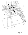
- Fig. 7
- eine perspektivische Teilansicht einer Außenseite des Gehäuse mit noch nicht montiertem Anschlussträger,
- Fig. 8
- eine Detailansicht in das Innere des Gehäuse mit montiertem Anschlussträger, und
- Fig. 9
- eine Detailansicht des Gehäuses mit in das Gehäuse hineingezogenem Anschlussträger.
- Die hier gezeigte Vorrichtung dient zum dezentralen Klimatisieren von Räumen. Ein Raum kann eine oder mehrere Vorrichtungen aufweisen. Die in den Figuren dargestellte Vorrichtung verfügt über eine Klimatisierungseinrichtung zum Heizen, Kühlen und Lüften des jeweiligen Raums. Das Lüften erfolgt mit Außenluft. Zum Heizen bzw. Kühlen ist die Vorrichtung an einem Kreislauf mit einem flüssigen Wärmeträgermittel und einem Kreislauf mit flüssigem Kälteträgermittel angeschlossen.
- Die gezeigte Vorrichtung ist als Bodenklimagerät ausgestaltet. Dazu ist die Vorrichtung im Boden eines Raums angeordnet, und zwar vorzugsweise unter einem Doppelboden. Die Vorrichtung erstreckt sich dann in einem Zwischenraum zwischen einem bauwerkseitigen Boden und dem mit Abstand darüber angeordneten Doppelboden.
- Die Vorrichtung verfügt über ein wannenartiges Gehäuse 10 mit einer rechteckförmigen Grundfläche. Das Gehäuse 10 verfügt über einen der Grundfläche entsprechenden rechteckförmigen Boden 11, der teilweise offen sein kann, zwei parallele Längsseitenwände 12 und 13 und zwei parallele Querseitenwände 14 und 15. Die etwa bündig mit dem Zwischenboden verlaufende Oberseite des Gehäuses 10 verfügt über eine vollflächige Öffnung 16. Die Grundfläche der Öffnung 16 entspricht derjenigen des Bodens 11.
- Die Vorrichtung verfügt des Weiteren über ein Nebengehäuse 17, das im gezeigten Ausführungsbeispiel wannenartig ausgebildet ist. Das Nebengehäuse 17 verfügt auch über eine rechteckförmige Grundfläche, wobei das Nebengehäuse 17 aber kleiner als das Gehäuse 10 ist. Das Nebengehäuse 17 ist kürzer als das Gehäuse 10 und auch etwas schmaler und niedriger. Eine im gezeigten Ausführungsbeispiel offene Unterseite 18 des Nebengehäuses 17 schließt bündig mit dem Boden 11 des Gehäuses 10 ab, so dass der Boden 11 und die Unterseite 18 etwa in einer Ebene liegen. Die Höhe des Nebengehäuses 17 ist so bemessen, dass dieses zwischen dem bauwerkseitigen Boden, beispielsweise einer Geschossdecke, und der Unterseite des Zwischenbodens unterbringbar ist. Das Nebengehäuse 17 ist derart kürzer als das Gehäuse 10 ausgebildet, dass der in Längsrichtung verlaufende Überstand des Gehäuses 10 gegenüber dem Nebengehäuse 17 genug Platz bietet für alle erforderlichen Anschlüsse der Klimatisierungseinrichtung, und zwar sowohl flüssigkeitsführende Leitungen als auch elektrische Kabel.
- Im gezeigten Ausführungsbeispiel ist das Nebengehäuse 17 gebildet aus drei aufrechten C-Profilen, die zwei gegenüberliegende, parallele Querseitenwände 19 und eine Längsseitenwand 20 bilden. Das seitlich neben dem Gehäuse 10 angeordnete Nebengehäuse 17 ist fest mit dem Gehäuse 10 verbunden. Diejenige Längsseite des Nebengehäuses 17, die zur Längsseitenwand 13 des Gehäuses 10 weist, verfügt über keine Längsseitenwand. Dadurch ist das Nebengehäuse 17 zur Seite des Gehäuses 10 vollständig offen. In der Längsseitenwand 13 des Gehäuses 10 ist eine Nebenöffnung 21 vorgesehen, die in der Größe einer Längsseite des Nebengehäuses 17 entspricht, nämlich mit der parallel zur Längsseitenwand 13 des Gehäuses 10 verlaufenden Längsseitenwand 20 des Nebengehäuses 17 korrespondiert. Durch die Nebenöffnung 21 ist das Innere des Nebengehäuses 17 vollflächig aus dem Gehäuse 10 her zugänglich.
- Die Querseitenwände 19 und die Längsseitenwand 20 des Nebengehäuses 17 werden von einem aufrechten Steg des im Querschnitt C-förmigen Profils gebildet. Parallele kurze Schenkel 22 der Profile der Längsseitenwand 20 und der Querseitenwände 19 liegen in parallelen horizontalen Ebenen, wobei die Ebene der unteren Schenkel 22 die Ebene des Bodens 18 des Nebengehäuses 17 bildet. Die oberen Schenkel 22 der Querseitenwände 19 und der Längsseitenwand 20 liegen in einer parallelen Ebene, die um die Dicke des Zwischenbodens unter der Ebene der Öffnung 16 im Gehäuse 10 liegt. Die oberen Schenkel 22 bilden dadurch eine Oberseite des Nebengehäuses 17. Sowohl diese Oberseite als auch die Unterseite 18 des Nebengehäuses 17 sind zwischen den Schenkeln 22 offen, wobei die zwischen den Schenkeln 22 teilweise offene Oberseite des Nebengehäuses 17 vom Doppelboden verschlossen wird.
- Das Gehäuse 10 verfügt über höhenverstellbare Füße 23. Hiermit steht das Gehäuse 10 samt den darin angeordneten Komponenten der Klimatisierungseinrichtung auf dem gebäudeseitigen Boden, beispielsweise einer Geschossdecke, auf. Durch eine individuelle Höhenverstellung der Füße 23 kann das Gehäuse 10 auf dem gehäuseseitigen Boden einjustiert und ausgerichtet werden. Das Nebengehäuse 17 ist an der zum Gehäuse 10 weisenden Längsseite durch Verbindung mit dem Gehäuse 10 an demselben abgestützt. An den außenseitigen Eckbereichen zwischen der Längsseitenwand 20 und den Querseitenwänden 19 ist auch das Nebengehäuse 17 auf dem gebäudeseitigen Boden abgestützt und dort befestigt durch Montagewinkel 24. Die Montagewinkel 24 sind gegenüber den Querseitenwänden 19 höhenverstellbar zum Ausrichten des Nebengehäuses 17.
- Das Gehäuse 10 wird mit der dem Nebengehäuse 17 gegenüberliegenden Längsseitenwand 12 an einer Innenseite einer Außen- bzw. Fassadenwand eines Gebäudes angeordnet und gegebenenfalls hiermit verbunden. Zur Versorgung der Klimatisierungseinrichtung mit der Außenluft weist die Längsseitenwand 12 einen Ausschnitt 25 auf, durch den Außenluft ins Innere des Gehäuses 10 leitbar ist. An der Innenseite der Längsseitenwand 12 sind neben gegenüberliegenden, aufrechten Rändern des Ausschnitts 25 Halterungen 26 für einen luftdicht an der Längsseitenwand 12 von der Innenseite des Gehäuses 10 her zu befestigenden Luftführungskanal, beispielsweise den Anschluss einer Außenluftklappe 27, vorgesehen. Die Halterungen 26 verfügen über gegenüberliegenden Querrändern des Ausschnitts 25 zugeordnete Halteschenkel 28, die geringfügig antiparallel zur Längsseitenwand 12 verlaufen, nämlich nach unten, zum Boden 11 des Gehäuses 10 hin, sich der Innenseite der Längsseitenwand 12 leicht annähern. Wenn ein Luftführungskanal, beispielsweise die Außenluftklappe 27, von der Innenseite des Gehäuses 10 vor der Längsseitenwand 12 positioniert wird, wozu Ränder des Luftführungskanals von oben her zwischen die Längsseitenwand 12 und die Halteschenkel 28 geschoben werden, erfolgt mit zunehmender Einschubtiefe in die Halteschenkel 28 ein sich verstärkendes Andrücken des Luftführungskanals, insbesondere einer diesen zugeordneten Dichtung, an die Längsseitenwand 12. Wenn der Luftführungskanal der Außenluftklappe 27 vor dem Ausschnitt 25 angeordnet ist, wird er von dem schräg zur Längsseitenwand 12 verlaufenden Halteschenkel 28 der Halterungen 26 mit seiner Dichtung gegen die Innenseite der Längsseitenwand 12 gedrückt und dabei automatisch die Abdichtung des Luftführungskanals gegenüber der Längsseitenwand 12 des Gehäuses 10 vorgenommen.
- Das Gehäuse 10 weist im gegenüber dem Nebengehäuse 17 in Längsrichtung vorstehenden Teil der zum Nebengehäuse 17 weisenden Längsseitenwand 13 eine Durchtrittsöffnung 29 auf. Die rechteckige Durchtrittsöffnung 29 verfügt über parallele horizontale Längsseitenränder 30, 31 und parallele, senkrechte Querseitenränder 32, 33. Die Durchtrittsöffnung 29 dient zum teilweisen Hindurchstecken und zum Halten eines Anschlussträgers 34. Der Anschlussträger 34 ist vorgesehen für elektrische Anschlüsse, und zwar sowohl zur Energieversorgung als auch zur Steuerung, der Klimatisierungseinrichtung im Gehäuse 10 und im Nebengehäuse 17. Der hier gezeigte Anschlussträger 34 verfügt in einer quer zur Längsseitenwand 13 verlaufenden senkrechten Ebene über einen C-förmigen Querschnitt. Dadurch weist der Anschlussträger 34 zwei parallele Schenkel 35, 36 und einen diese verbindenden, horizontalen Steg 37 auf. Die Schenkel 35, 36 verlaufen mit parallelem Abstand zueinander und liegen bei am Gehäuse 10 befestigten Anschlussträger 34 in parallel zur Längsseitenwand 13 verlaufenden Ebenen.
- Der Anschlussträger 34 ist so ausgebildet, dass er durch die Durchtrittsöffnung 29 in der Längsseitenwand 13 hindurchsteckbar und mit von innen an der Längsseitenwand 13 anliegendem Schenkel 35 an der Längsseitenwand 13 des Gehäuses 10 befestigbar ist, vorzugsweise lösbar durch Schrauben oder dergleichen. Damit der Anschlussträger 34 mit dem Schenkel 35 von innen vor der Längsseitenwand 13 sich befestigen lässt, verfügt der Schenkel 35 über eine Breite, die größer ist als die Breite der Durchtrittsöffnung 29, indem gegenüberliegende Endbereiche 38 des Schenkels 35 die gegenüberliegenden Querseitenränder 32 und 33 der Längsseitenwand 13 überlappen. In diesen Überlappungsbereichen kann die Verbindung des Anschlussträgers 34 mit dem Gehäuse 10 erfolgen. Die Länge bzw. Höhe des Schenkels 36 ist so bemessen, dass sie der Höhe der Durchtrittsöffnung 29, also der Länge der Querseitenränder 32, 33 entspricht, vorzugsweise etwas kleiner ist. Der hintere Schenkel 36 und auch der Steg 37 weisen eine Breite auf, die der Breite der Durchtrittsöffnung 29, also der Länge der Längsseitenränder 30, 31 entspricht, vorzugsweise etwas kleiner ist.
- Der Steg 37 des Anschlussträgers 34 weist in seinem an den Schenkel 35 anschließenden Bereich gegenüberliegende Einschnitte 40 auf, die von Querkanten 41 des Stegs 37 ausgehen. Die Einschnitte 40 sind etwas breiter als die Dicke der Längsseitenwand 13 und so tief wie der jeweilige seitliche Überstand des Schenkels 35 gegenüber den Querkanten 41, vorzugsweise etwas tiefer. Dadurch lässt sich der Anschlussträger 34 trotz des breiteren vorderen Schenkels 35 schräg durch die Durchtrittsöffnung 29 hindurchstecken, indem zunächst der Einschnitt 40 auf einer Seite des Anschlussträgers 34 über einen Querseitenrand 33 bzw. 34 der Durchtrittsöffnung 29 in der Längsseitenwand 13 geschoben wird, wodurch der auf der gegenüberliegenden Seite gegenüber der Querkante 41 vorstehende Randbereich des Schenkels 35 in den Bereich der Durchtrittsöffnung 29 gelangt und dadurch der Anschlussträger 34 mit dem Schenkel 35 von außen ins Innere des Gehäuses 10 gesteckt werden kann. Weil der hintere Schenkel 36 und der Steg 37 nicht über die Breite der Durchtrittsöffnung 29 hinausgehen, kann nach dem Hindurchstecken des vorderen Schenkels 35 durch die Durchtrittsöffnung 29 der gesamte Anschlussträger 34 durch die Durchtrittsöffnung 29 hindurchgesteckt werden, so dass sich der gesamte Anschlussträger 34 im Inneren des Gehäuses 10 befindet (
Fig. 9 ). - Die zuvor beschriebene besondere Ausbildung des Anschlussträgers 34 ermöglicht es, diesen mit montierten Kabeln durch die Durchtrittsöffnung 29 hindurchzustecken und von der Innenseite des Gehäuses 10 her von der Innenseite der Längsseitenwand 13 durch zum Beispiel Schrauben zu befestigen. Der Anschlussträger 34 kann aber auch mit montierten Kabeln vollständig in das Gehäuse 10 gezogen werden. Der gezeigte Anschlussträger 34 ist für zwei Kabel 42, 43 vorgesehen. Die beiden Kabel 42, 43 sind mit Kabelsteckern 44 an ihren Enden versehen, wobei dem Kabel 43 drei Kabelstecker 44 zugeordnet sind. Die Kabel 42, 43 dienen zur Versorgung der Klimatisierungseinrichtung mit elektrischer Energie und zur Steuerung der Klimatisierungseinrichtung. Auf die in den Figuren gezeigte Anzahl der Kabel 42, 43 und Kabelstecker 44 ist die Erfindung aber nicht beschränkt. Die Kabelstecker 44 sind mit dem (breiteren) Schenkel 35 verbunden, und zwar vorzugsweise lösbar. Der Schenkel 35 des Anschlussträgers 34 dient dadurch gleichzeitig zum Halten der Kabelstecker 44. Mit dem hinteren Schenkel 36 sind Kabeldurchführungen 45 verbunden, wodurch die Kabel 42 und 43 hindurchgeführt sind. Die Kabeldurchführungen 45 dienen dabei gleichzeitig zur Zugentlastung der Kabel 42, 43.
- Im gezeigten Ausführungsbeispiel verfügt der Schenkel 35 über eine freie Ausnehmung 46, die bei Bedarf mit weiteren Kabelsteckern 44 bestückt werden kann. Der Anschlussträger 34 kann auch mit einer größeren Anzahl von Reserve-Ausnehmungen 46 versehen sein. Auch ist es denkbar, im hinteren Schenkel 36 mehrere, insbesondere überzählige, Aufnahmen für Kabeldurchführungen 45 vorzusehen.
- Innerhalb der Durchtrittsöffnung 29 für den Anschlussträger 34 sind in der Längsseitenwand 13 im gezeigten Ausführungsbeispiel vier Kupplungen 47 zum Anschluss jeweils einer Vor- und Rücklaufleitung für das Kälteträgermedium und das Wärmeträgermedium vorgesehen. Den Kupplungen 47 sind im Inneren des Gehäuses 10 angeordnete Ventile 48 zugeordnet. Im gezeigten Ausführungsbeispiel sind den Ventilen 48 noch Absperrhähne 49 zugeordnet, vorzugsweise nachgeordnet. Die Ventile 48 sind bevorzugt fernbedient verstellbar.
- Bei der Montage der Vorrichtung wird so vorgegangen, dass zunächst das Gehäuse 10 und das Nebengehäuse 17 montiert werden. Dabei erfolgt ein Ausrichten des Gehäuses 10 und des Nebengehäuses 17 mit den Füßen 23 und den Montagewinkeln 24. Gegebenenfalls erfolgt ein Befestigen des Gehäuses 10 und vorzugsweise auch des Nebengehäuses 17 auf dem gebäudeseitigen Boden. Zusätzlich kann die zur Außenwand bzw. Fassade weisende Längsseitenwand 12 des Gehäuses 10 mit der Außenwand fest verbunden werden, wobei gegebenenfalls auch eine Abdichtung des den Ausschnitt 25 für die Außenluftklappe 27 umgebenden Randes in der Längsseitenwand 12 gegenüber der Außenwand bzw. Fassade erfolgt. Dann wird der Zwischenboden mit einem zur Öffnung 16 im Gehäuse 10 korrespondierenden Ausschnitt über der Öffnung 16 eingebaut. Erst wenn der Bau fast fertiggestellt ist, werden die Innenteile, vor allem die Komponenten der Klimatisierungseinrichtung, in das Nebengehäuse 17 und das Gehäuse 10 eingebracht.
- Die
Fig. 1 bis 5 zeigen einzelne Abschnitte der Montage der Komponenten der Klimatisierungseinrichtung im Nebengehäuse 17 und im Gehäuse 10. - In der
Fig. 1 ist gestrichelt eine Außenluftventilatoreinheit 50 vor der Montage gezeigt. Die Außenluftventilatoreinheit 50 wird durch die obere Öffnung 16 in das Gehäuse 10 abgesetzt, und zwar gegebenenfalls mit einer leichten Kippbewegung. Vom Gehäuse 10 wird die Außenluftventilatoreinheit 50 durch die Nebenöffnung 21 in das Nebengehäuse 17 geschoben. Die Außenluftventilatoreinheit 50 ist mindestens teilweise von einem Rahmen umgeben, dessen Eckbereiche hinsichtlich der Abmessungen den lichten Innenmassen des Nebengehäuses 17 entsprechen, nämlich mit dem Abstand zwischen den Schenkeln 22 des C-Profils der Querseitenwände 19 des Nebengehäuses 17 korrespondieren. Die Schenkel 22 dienen dabei als Führungsschienen zum gleitenden Einschieben der Außenluftventilatoreinheit 50 in das Nebengehäuse 17. - Die Außenluftventilatoreinheit 50 weist im gezeigten Ausführungsbeispiel einen Ventilator, beispielsweise einen Radialventilator 51 und einen Schalldämpfer 52, auf (
Fig. 4 ). Vom Radialventilator 51 wird durch im Gehäuse 10 angeordneten Teilen der Klimatisierungsanlage Außenluft angesaugt, die nach Passieren des Schalldämpfers 52 durch die Nebenöffnung 21 wieder in das Gehäuse 10 gelangt und hieraus nach oben durch einen den Ausschnitt für das Gehäuse 10 im Doppelboden verschließenden Rost 58 verlässt und so als aufwärts gerichtete Strömung in den Raum gelangt. - Nach dem Montieren der Außenluftventilatoreinheit 50 im Nebengehäuse 17 wird ein Wanneneinsatz 53 durch die obere Öffnung 16 in das Gehäuse 10 eingesetzt. Der Wanneneinsatz 53 erstreckt sich nur über einen Teil der Länge des Gehäuses 10, und zwar nur soweit, wie das Nebengehäuse 17 reicht (
Fig. 3 ). In Längsrichtung des Wanneneinsatzes 53 gesehen ist ein Teil desselben, der sich etwa über dem Bereich des Ausschnitts 25 zum Eintritt von Außenluft in das Gehäuse 10 erstreckt, mit der Außenluftklappe 27, einem Antrieb 54 zum Verstellen der Außenluftklappe 27 und einem Filter, insbesondere einen Pollenfilter 55, versehen. Auf diese Weise gelangt eine über die Außenluftklappe 27 vorgegebene Außenluftmenge durch den Pollenfilter 55 zum Radialventilator 51 im Nebengehäuse 17. - Der verbleibende Restraum längs des Wannenseinsatzes 53 wird eingenommen durch einen Wärmetauscher 56 und einen Querstromventilator 57. Der Wärmetauscher 56 und der Querstromventilator 57 liegen nebeneinander längsgerichtet im Wanneneinsatz 53, wobei der Querstromventilator 57 auf der zur Außenluftventilatoreinheit 50 im Nebengehäuse 17 weisenden Seite des Gehäuses 10 liegt (
Fig. 4 ). Vom Querstromventilator 57 wird ein Umluftstrom erzeugt. Dabei wird Raumluft angesaugt und am Wärmetauscher 56 vorbeigeleitet. Oberhalb des Wärmetauschers 56 gelangt von diesem erwärmte oder abgekühlte Umluft wieder in den Raum. Der Querstromventilator 57 dient somit als Umluftventilator. Frischluft kann je nach Betrieb der Vorrichtung von der Außenluftventilatoreinheit 50 im Nebengehäuse 17 auch am Wärmetauscher 50 vorbeigeleitet und dabei gekühlt oder erwärmt werden. Frischluft kann aber auch ohne ein Kühlen oder Erwärmen in den Raum strömen. - Nachdem die vorstehend genannten Hauptkomponenten und weitere Zusatzteile, wie beispielsweise Kondensatwannen, Filter, Abdeckungen oder dergleichen in dem Gehäuse 10 und dem Nebengehäuse 17 installiert worden sind, werden die Anschlüsse hergestellt. Dazu werden nicht gezeigte Kabelstecker insbesondere des Radialventilators 51, des Querstromventilators 57 und des Antriebs 54 für die Außenluftklappe 27 sowie die Steuerung mit den Kabelsteckern 44 des Anschlussträgers 34 verbunden. Außerdem werden durch die Kupplungen 47, vorzugsweise in Gestalt von Schnellverschlüssen, die Leitungen des Wärmetauschers 56 an die Ventile 48 angeschlossen. Die Vorrichtung ist dann grundsätzlich einsatzbereit. Es ist lediglich die Öffnung 16 im Gehäuse 10 noch durch ein Rost 58, beispielsweise ein Quer- oder ein Längsrost, zu verschließen. Es können auch mehrere getrennte Roste vorgesehen sein.
- Im gezeigten Ausführungsbeispiel sind über dem Wärmetauscher 56 und dem Querstromventilator 57 noch eine Abdeckung 59 und eine darauf liegende Filterbahn 60 vorgesehen. Die Abdeckung 59 stützt sich bevorzugt im oder am Gehäuse 10 ab, um als Abstützung für den Rost 58 zu dienen. Im von der Außenluftklappe 27, dem Wärmetauscher 56 und dem Querstromventilator 57 frei gelassenen stirnseitigen Teilraum des Gehäuses 10, indem sich die Kabelstecker 44 auf dem Anschlussträger 34 und die Kupplungen 47, die Ventile 48 sowie die Absperrhähne 49 befinden, ist noch eine Regelung 61 angeordnet.
- Die Räume in gegenüberliegenden Endbereichen des Gehäuses 10 zur Aufnahme der Außenluftklappe 27 mit dem Antrieb 54 einerseits und Kabelstecker 44, Kupplungen 47, Ventile 48, Absperrhähne 49 und die Regelung 61 anderseits sind durch von oben in die Öffnung 16 des Gehäuses 10 eingesetzte Abdeckungen 62, 63 verschlossen. Die Abdeckung 62, 63 sind lose auf die Öffnung 16 des Gehäuses 10 aufgelegt, so dass sie insbesondere zu Wartungszwecken entfernt werden können. Über den Abdeckungen 62, 63 erstreckt sich der Rost 58, der dadurch die gesamte Öffnung 16 des Gehäuses 10 nach oben hin abschließt. Die Oberseite des Rosts 58 schließt bevorzugt bündig mit der Oberfläche des Zwischenbodens ab.
- Die Erfindung eignet sich nicht nur für die in den Figuren gezeigte Klimatisierungseinrichtung, sondern für beliebig konfigurierte und aufgebaute Klimatisierungseinrichtungen, auch solche, die nicht zum Lüften, Kühlen und Heizen dienen, sondern nur einige der genannten Klimatisierungsaufgaben erfüllen. Denkbar ist es auch, dass die Vorrichtung bzw. die Klimatisierungseinrichtung nur über einen einzigen Ventilator verfügt, so dass der als Umluftventilator dienende Querstromventilator 57 entfällt. Es ist auch denkbar, dass die Vorrichtung über keine Lüftungsmöglichkeit mit Außenluft verfügt. Eine solche Vorrichtung erfordert keinen Außenluftanschluss. Die Klimatisierungseinrichtung ist dann aus einer reinen Umlufteinheit gebildet, die vorzugsweise über eine stärkere Kühlleistung verfügt als die beschriebene Vorrichtung mit einer Außenlufteinheit.
- Die Erfindung eignet sich auch für unter einer Raumdecke hängend angeordnete Vorrichtungen zur Klimatisierung von Räumen. Solche Vorrichtungen sind zwischen einer Geschossdecke und einer Zwischendecke angeordnet. Das Gehäuse ist an den Unterseiten mit einem Deckenrost versehen, wobei das Nebengehäuse sich im Raum über der Zwischendecke befindet und von dieser verdeckt ist.
-
- 10
- Gehäuse
- 11
- Boden
- 12
- Längsseitenwand
- 13
- Längsseitenwand
- 14
- Querseitenwand
- 15
- Querseitenwand
- 16
- Öffnung
- 17
- Nebengehäuse
- 18
- Unterseite
- 19
- Querseitenwand
- 20
- Längsseitenwand
- 21
- Nebenöffnung
- 22
- Schenkel
- 23
- Fuß
- 24
- Montagewinkel
- 25
- Ausschnitt
- 26
- Halterung
- 27
- Außenluftklappe
- 28
- Halteschenkel
- 29
- Durchtrittsöffnung
- 30
- Längsseitenrand
- 31
- Längsseitenrand
- 32
- Querseitenrand
- 33
- Querseitenrand
- 34
- Anschlussträger
- 35
- Schenkel
- 36
- Schenkel
- 37
- Steg
- 38
- Endbereich
- 39
- 40
- Einschnitt
- 41
- Querkante
- 42
- Kabel
- 43
- Kabel
- 44
- Kabelstecker
- 45
- Kabeldurchführung
- 46
- Ausnehmung
- 47
- Kupplung
- 48
- Ventil
- 49
- Absperrhahn
- 50
- Außenluftventilatoreinheit
- 51
- Radialventilator
- 52
- Schalldämpfer
- 53
- Wanneneinsatz
- 54
- Antrieb
- 55
- Pollenfilter
- 56
- Wärmetauscher
- 57
- Querstromventilator
- 58
- Rost
- 59
- Abdeckung
- 60
- Filterbahn
- 61
- Regelung
- 62
- Abdeckung
- 63
- Abdeckung
Claims (13)
- Vorrichtung zur Klimatisierung von Räumen mit einem eine abdeckbare Öffnung (16) aufweisenden Gehäuse (10) zur Aufnahme mindestens eines Teils einer Klimatisierungseinrichtung, wobei vorzugsweise die Öffnung (16) durch mindestens einen Rost (58) oder dergleichen abdeckbar ist, dadurch gekennzeichnet, dass dem Gehäuse (10) mindestens ein Nebengehäuse (17) zugeordnet ist, das durch eine Nebenöffnung (21) vom Gehäuse (10) aus zugänglich ist.
- Vorrichtung nach Anspruch 1, dadurch gekennzeichnet, dass das Nebengehäuse (17) mit dem Gehäuse (10) verbunden ist, vorzugsweise mit einer Längsseitenwand (13) des Gehäuses (10).
- Vorrichtung nach Anspruch 1 oder 2, dadurch gekennzeichnet, dass die Nebenöffnung (21) in derjenigen Wandung des Gehäuses (10) und/oder des Nebengehäuses (17) angeordnet ist, an der das Nebengehäuse (17) mit dem Gehäuse (10) verbunden ist, vorzugsweise der Längsseitenwand (13) des Gehäuses (10).
- Vorrichtung nach einem der vorhergehenden Ansprüche, dadurch gekennzeichnet, dass die Nebenöffnung (21) sich über mindestens einen Großteil, vorzugsweise eine gesamte Wandung des Nebengehäuses (17), erstreckt, insbesondere eine gesamte Längswand des Nebengehäuses (17).
- Vorrichtung nach einem der vorhergehenden Ansprüche, dadurch gekennzeichnet, dass das Nebengehäuse (17) an einer Längsseitenwand (13) des Gehäuses (10) angeordnet ist, vorzugsweise von außen an der Längsseitenwand (13) des Gehäuses (10) befestigt ist.
- Vorrichtung nach einem der vorhergehenden Ansprüche, dadurch gekennzeichnet, dass die Grundfläche des Nebengehäuses (17) kleiner ist als die Grundfläche des Gehäuses (10), vorzugsweise mindestens schmaler.
- Vorrichtung nach einem der vorhergehenden Ansprüche, dadurch gekennzeichnet, dass die Höhe des Nebengehäuses (17) geringer ist als die Höhe des Gehäuses (10), wobei vorzugsweise eine Ober- oder Unterseite des Nebengehäuses (17) unterhalb oder oberhalb der Ebene der durch das mindestens eine Rost (58) abdeckbaren Öffnung (16) des Gehäuses (10) liegt.
- Vorrichtung nach einem der vorhergehenden Ansprüche, dadurch gekennzeichnet, dass das Nebengehäuse (17) Führungen zum Einschieben mindestens eines Teils der Klimatisierungseinrichtung, vorzugsweise eine Außenluftventilatoreinheit (50), vom Gehäuse (10) durch die Nebenöffnung (21) in das Nebengehäuse (17) aufweist.
- Vorrichtung zur Klimatisierung von Räumen mit einem eine durch vorzugsweise mindestens ein Rost (58) oder dergleichen abdeckbare Öffnung (16) aufweisenden Gehäuse (10) zur Aufnahme mindestens eines Teils einer Klimatisierungseinrichtung, insbesondere nach einem oder mehreren der vorherigen Ansprüche, dadurch gekennzeichnet, dass das Gehäuse (10) mindestens eine Durchtrittsöffnung (29) zum Hindurchführen eines Anschlussträgers (34) mit montierten Kabeln (42, 43) und/oder Anschlüssen aufweist.
- Vorrichtung nach einem der vorhergehenden Ansprüche, dadurch gekennzeichnet, dass die Abmessung des Anschlussträgers (34) in einer Erstreckungsrichtung gleich, vorzugsweise etwas kleiner, als die korrespondierende Abmessung der Durchtrittsöffnung (29) ist.
- Vorrichtung nach einem der vorhergehenden Ansprüche, dadurch gekennzeichnet, dass der Anschlussträger (34) einen U-förmigen Querschnitt aufweist, mit zwei parallelen Schenkeln (35, 36) und einen diese verbindenden Steg (37), wobei vorzugsweise an einem Schenkel (35) Kabelstecker (44) befestigt sind und am anderen Schenkel (36) die Kabel (42, 43) mit einer zur Zugentlastung dienenden Kabeldurchführung (45) fixiert sind.
- Vorrichtung nach einem der vorhergehenden Ansprüche, dadurch gekennzeichnet, dass der Steg (37) gegenüberliegende Einschnitte (40) in einem an den die Kabelstecker (44) haltenden Schenkel (35) angrenzenden Bereich aufweist.
- Vorrichtung nach einem der vorhergehenden Ansprüche, dadurch gekennzeichnet, dass der die Kabelstecker (44) tragende Schenkel (35) des Anschlussträgers (34) breiter als die Durchtrittsöffnung (29) im Gehäuse (10) ist und die Einschnitte (40) im Steg (37) zum Eintritt von Randbereichen der Durchtrittsöffnung (29) dienen zum Verschieben des Anschlussträgers (34), insbesondere des die Kabelstecker (44) haltenden Schenkels (35), vor der Durchtrittsöffnung (29) im Gehäuse (10).
Applications Claiming Priority (2)
| Application Number | Priority Date | Filing Date | Title |
|---|---|---|---|
| DE102007049730 | 2007-10-16 | ||
| DE102007056997A DE102007056997A1 (de) | 2007-10-16 | 2007-11-27 | Vorrichtung zur Klimatisierung von Räumen |
Publications (3)
| Publication Number | Publication Date |
|---|---|
| EP2051017A2 true EP2051017A2 (de) | 2009-04-22 |
| EP2051017A3 EP2051017A3 (de) | 2014-07-02 |
| EP2051017B1 EP2051017B1 (de) | 2021-11-10 |
Family
ID=40053007
Family Applications (1)
| Application Number | Title | Priority Date | Filing Date |
|---|---|---|---|
| EP08016338.9A Active EP2051017B1 (de) | 2007-10-16 | 2008-09-17 | Vorrichtung zur klimatisierung von räumen |
Country Status (1)
| Country | Link |
|---|---|
| EP (1) | EP2051017B1 (de) |
Cited By (4)
| Publication number | Priority date | Publication date | Assignee | Title |
|---|---|---|---|---|
| ITPD20120187A1 (it) * | 2012-06-08 | 2013-12-09 | Pierantonio Martini | Struttura perfezionata di terminale di convezione per impianti di climatizzazione, principalmente per installazioni ad incasso a pavimento |
| FR3020127A1 (fr) * | 2014-04-17 | 2015-10-23 | France Air | Convecteur de sol et installation de ventilation comprenant un tel convecteur de sol |
| CN104359152B (zh) * | 2014-10-10 | 2017-05-17 | 深圳市共济科技股份有限公司 | 一种模块多联精密空调系统及其散热方法 |
| CN114616427A (zh) * | 2019-11-05 | 2022-06-10 | 大金工业株式会社 | 空调室内机和空调装置 |
Family Cites Families (9)
| Publication number | Priority date | Publication date | Assignee | Title |
|---|---|---|---|---|
| JPS60263042A (ja) * | 1984-06-08 | 1985-12-26 | Misawa Homes Co Ltd | セパレ−ト型空気調和機 |
| EP0207718B1 (de) * | 1985-07-05 | 1990-12-27 | Atlas Air (Australia) Pty. Limited | Klimaanlage für begrenzten Wirkungsbereich |
| JPH045926Y2 (de) * | 1988-01-11 | 1992-02-19 | ||
| DE19548599C2 (de) * | 1995-12-23 | 1998-07-02 | Fsl Fenster System Lueftung | Lüftungssystem für die Räume von Gebäuden |
| US6301914B1 (en) * | 2000-08-17 | 2001-10-16 | Carrier Corporation | Room air conditioner having outdoor power cord |
| DE20219225U1 (de) * | 2002-12-12 | 2003-02-20 | Gebrüder Trox Gesellschaft mit beschränkter Haftung, 47506 Neukirchen-Vluyn | Belüftungssystem zur Raumbelüftung |
| DE102004010738A1 (de) * | 2004-03-05 | 2005-09-22 | Ltg Aktiengesellschaft | Raumlufttechnische Einrichtung zum Heizen, Kühlen und/oder Belüften eines Raumes sowie entsprechendes Verfahren |
| DE102004036886A1 (de) * | 2004-07-22 | 2006-02-16 | Ltg Aktiengesellschaft | Lufttechnische Einrichtung und Verfahren zum Heizen, Kühlen und/oder Belüften eines Raumes |
| DE102005022241A1 (de) * | 2005-05-13 | 2006-11-16 | Ltg Ag | Raumlufttechnische Anlage sowie entsprechendes Verfahren |
-
2008
- 2008-09-17 EP EP08016338.9A patent/EP2051017B1/de active Active
Cited By (8)
| Publication number | Priority date | Publication date | Assignee | Title |
|---|---|---|---|---|
| ITPD20120187A1 (it) * | 2012-06-08 | 2013-12-09 | Pierantonio Martini | Struttura perfezionata di terminale di convezione per impianti di climatizzazione, principalmente per installazioni ad incasso a pavimento |
| EP2672189A1 (de) * | 2012-06-08 | 2013-12-11 | Pierantonio Martini | Konvektionsanschluss für Klimasteuerungssysteme, hauptsächlich für im Boden versenkte Installationen |
| FR3020127A1 (fr) * | 2014-04-17 | 2015-10-23 | France Air | Convecteur de sol et installation de ventilation comprenant un tel convecteur de sol |
| CN104359152B (zh) * | 2014-10-10 | 2017-05-17 | 深圳市共济科技股份有限公司 | 一种模块多联精密空调系统及其散热方法 |
| CN114616427A (zh) * | 2019-11-05 | 2022-06-10 | 大金工业株式会社 | 空调室内机和空调装置 |
| US20220260259A1 (en) * | 2019-11-05 | 2022-08-18 | Daikin Industries, Ltd. | Air conditioning indoor unit and air conditioner |
| EP4056924A4 (de) * | 2019-11-05 | 2022-12-21 | Daikin Industries, Ltd. | Klimaanlageninnenraumeinheit und klimaanlage |
| US12405013B2 (en) * | 2019-11-05 | 2025-09-02 | Daikin Industries, Ltd. | Air conditioning indoor unit and air conditioner |
Also Published As
| Publication number | Publication date |
|---|---|
| EP2051017A3 (de) | 2014-07-02 |
| EP2051017B1 (de) | 2021-11-10 |
Similar Documents
| Publication | Publication Date | Title |
|---|---|---|
| EP1719044A2 (de) | Ger teanordnung | |
| DE102008033792A1 (de) | Umluftmodul und Dunstabzugsvorrichtung | |
| DE202014100664U1 (de) | Kühlregal | |
| EP1832818B1 (de) | Lüftungsanlage | |
| EP2051017B1 (de) | Vorrichtung zur klimatisierung von räumen | |
| DE602004000084T2 (de) | Baugruppe zur installation von leistungselektronikmodulen und installationsverfahren | |
| DE202014100662U1 (de) | Kühlregal | |
| DE102007056997A1 (de) | Vorrichtung zur Klimatisierung von Räumen | |
| DE3416574A1 (de) | Modulare steuer- und pumpeneinheit fuer heizzentralen und dergleichen | |
| DE202011110056U1 (de) | Klimaschrank | |
| DE202014100665U1 (de) | Kühlregal | |
| DE1604299C3 (de) | Induktionsgerät für Hochdruckklimaanlagen | |
| EP2708827B1 (de) | Luftaus- oder -einlass und Lüftungssystem hiermit | |
| DE10255172A1 (de) | Raumlüftungsgerät | |
| CH716781B1 (de) | Dunstabzugsvorrichtung für ein Küchengerät. | |
| EP3124869B1 (de) | Luftauslassgitter, insbesondere für einen ofen | |
| DE202008010063U1 (de) | Lufttechnische Einrichtung | |
| EP3985313A1 (de) | Wärmeverteilanlage | |
| DE10016091B4 (de) | Hohlwand | |
| DE10106646C1 (de) | Mauerkasten für Abluft- und Zuluft-Durchleitung durch eine Wand | |
| EP3050412B1 (de) | Anordnung sowie verfahren zum kühlen eines raums | |
| EP3106766A1 (de) | Unterflurklimatisierungsvorrichtung | |
| DE2110781A1 (de) | Vorrichtung zum Heizen oder Kuehlen von Raeumen | |
| DE102015010199A1 (de) | Unterflurklimatisierungsvorrichtung | |
| DE102015006762A1 (de) | Unterflurklimatisierungsvorrichtung |
Legal Events
| Date | Code | Title | Description |
|---|---|---|---|
| PUAI | Public reference made under article 153(3) epc to a published international application that has entered the european phase |
Free format text: ORIGINAL CODE: 0009012 |
|
| AK | Designated contracting states |
Kind code of ref document: A2 Designated state(s): AT BE BG CH CY CZ DE DK EE ES FI FR GB GR HR HU IE IS IT LI LT LU LV MC MT NL NO PL PT RO SE SI SK TR |
|
| AX | Request for extension of the european patent |
Extension state: AL BA MK RS |
|
| PUAL | Search report despatched |
Free format text: ORIGINAL CODE: 0009013 |
|
| AK | Designated contracting states |
Kind code of ref document: A3 Designated state(s): AT BE BG CH CY CZ DE DK EE ES FI FR GB GR HR HU IE IS IT LI LT LU LV MC MT NL NO PL PT RO SE SI SK TR |
|
| AX | Request for extension of the european patent |
Extension state: AL BA MK RS |
|
| RIC1 | Information provided on ipc code assigned before grant |
Ipc: F24F 1/00 20110101AFI20140526BHEP Ipc: F24F 13/20 20060101ALI20140526BHEP Ipc: F24F 1/26 20110101ALI20140526BHEP |
|
| 17P | Request for examination filed |
Effective date: 20141010 |
|
| RBV | Designated contracting states (corrected) |
Designated state(s): AT BE BG CH CY CZ DE DK EE ES FI FR GB GR HR HU IE IS IT LI LT LU LV MC MT NL NO PL PT RO SE SI SK TR |
|
| AKX | Designation fees paid |
Designated state(s): AT BE BG CH CY CZ DE DK EE ES FI FR GB GR HR HU IE IS IT LI LT LU LV MC MT NL NO PL PT RO SE SI SK TR |
|
| AXX | Extension fees paid |
Extension state: MK Extension state: RS Extension state: AL Extension state: BA |
|
| STAA | Information on the status of an ep patent application or granted ep patent |
Free format text: STATUS: EXAMINATION IS IN PROGRESS |
|
| 17Q | First examination report despatched |
Effective date: 20170817 |
|
| RAP1 | Party data changed (applicant data changed or rights of an application transferred) |
Owner name: KAMPMANN GMBH & CO. KG |
|
| GRAP | Despatch of communication of intention to grant a patent |
Free format text: ORIGINAL CODE: EPIDOSNIGR1 |
|
| STAA | Information on the status of an ep patent application or granted ep patent |
Free format text: STATUS: GRANT OF PATENT IS INTENDED |
|
| INTG | Intention to grant announced |
Effective date: 20210430 |
|
| RIN1 | Information on inventor provided before grant (corrected) |
Inventor name: SABELHAUS, CLEMENS |
|
| GRAS | Grant fee paid |
Free format text: ORIGINAL CODE: EPIDOSNIGR3 |
|
| GRAA | (expected) grant |
Free format text: ORIGINAL CODE: 0009210 |
|
| STAA | Information on the status of an ep patent application or granted ep patent |
Free format text: STATUS: THE PATENT HAS BEEN GRANTED |
|
| AK | Designated contracting states |
Kind code of ref document: B1 Designated state(s): AT BE BG CH CY CZ DE DK EE ES FI FR GB GR HR HU IE IS IT LI LT LU LV MC MT NL NO PL PT RO SE SI SK TR |
|
| REG | Reference to a national code |
Ref country code: GB Ref legal event code: FG4D Free format text: NOT ENGLISH |
|
| REG | Reference to a national code |
Ref country code: AT Ref legal event code: REF Ref document number: 1446430 Country of ref document: AT Kind code of ref document: T Effective date: 20211115 Ref country code: CH Ref legal event code: EP |
|
| REG | Reference to a national code |
Ref country code: DE Ref legal event code: R096 Ref document number: 502008017233 Country of ref document: DE |
|
| REG | Reference to a national code |
Ref country code: IE Ref legal event code: FG4D Free format text: LANGUAGE OF EP DOCUMENT: GERMAN |
|
| REG | Reference to a national code |
Ref country code: LT Ref legal event code: MG9D |
|
| PG25 | Lapsed in a contracting state [announced via postgrant information from national office to epo] |
Ref country code: LT Free format text: LAPSE BECAUSE OF FAILURE TO SUBMIT A TRANSLATION OF THE DESCRIPTION OR TO PAY THE FEE WITHIN THE PRESCRIBED TIME-LIMIT Effective date: 20211110 Ref country code: FI Free format text: LAPSE BECAUSE OF FAILURE TO SUBMIT A TRANSLATION OF THE DESCRIPTION OR TO PAY THE FEE WITHIN THE PRESCRIBED TIME-LIMIT Effective date: 20211110 Ref country code: BG Free format text: LAPSE BECAUSE OF FAILURE TO SUBMIT A TRANSLATION OF THE DESCRIPTION OR TO PAY THE FEE WITHIN THE PRESCRIBED TIME-LIMIT Effective date: 20220210 |
|
| PG25 | Lapsed in a contracting state [announced via postgrant information from national office to epo] |
Ref country code: IS Free format text: LAPSE BECAUSE OF FAILURE TO SUBMIT A TRANSLATION OF THE DESCRIPTION OR TO PAY THE FEE WITHIN THE PRESCRIBED TIME-LIMIT Effective date: 20220310 Ref country code: SE Free format text: LAPSE BECAUSE OF FAILURE TO SUBMIT A TRANSLATION OF THE DESCRIPTION OR TO PAY THE FEE WITHIN THE PRESCRIBED TIME-LIMIT Effective date: 20211110 Ref country code: PT Free format text: LAPSE BECAUSE OF FAILURE TO SUBMIT A TRANSLATION OF THE DESCRIPTION OR TO PAY THE FEE WITHIN THE PRESCRIBED TIME-LIMIT Effective date: 20220310 Ref country code: PL Free format text: LAPSE BECAUSE OF FAILURE TO SUBMIT A TRANSLATION OF THE DESCRIPTION OR TO PAY THE FEE WITHIN THE PRESCRIBED TIME-LIMIT Effective date: 20211110 Ref country code: NO Free format text: LAPSE BECAUSE OF FAILURE TO SUBMIT A TRANSLATION OF THE DESCRIPTION OR TO PAY THE FEE WITHIN THE PRESCRIBED TIME-LIMIT Effective date: 20220210 Ref country code: NL Free format text: LAPSE BECAUSE OF FAILURE TO SUBMIT A TRANSLATION OF THE DESCRIPTION OR TO PAY THE FEE WITHIN THE PRESCRIBED TIME-LIMIT Effective date: 20211110 Ref country code: LV Free format text: LAPSE BECAUSE OF FAILURE TO SUBMIT A TRANSLATION OF THE DESCRIPTION OR TO PAY THE FEE WITHIN THE PRESCRIBED TIME-LIMIT Effective date: 20211110 Ref country code: HR Free format text: LAPSE BECAUSE OF FAILURE TO SUBMIT A TRANSLATION OF THE DESCRIPTION OR TO PAY THE FEE WITHIN THE PRESCRIBED TIME-LIMIT Effective date: 20211110 Ref country code: GR Free format text: LAPSE BECAUSE OF FAILURE TO SUBMIT A TRANSLATION OF THE DESCRIPTION OR TO PAY THE FEE WITHIN THE PRESCRIBED TIME-LIMIT Effective date: 20220211 Ref country code: ES Free format text: LAPSE BECAUSE OF FAILURE TO SUBMIT A TRANSLATION OF THE DESCRIPTION OR TO PAY THE FEE WITHIN THE PRESCRIBED TIME-LIMIT Effective date: 20211110 |
|
| PG25 | Lapsed in a contracting state [announced via postgrant information from national office to epo] |
Ref country code: SK Free format text: LAPSE BECAUSE OF FAILURE TO SUBMIT A TRANSLATION OF THE DESCRIPTION OR TO PAY THE FEE WITHIN THE PRESCRIBED TIME-LIMIT Effective date: 20211110 Ref country code: RO Free format text: LAPSE BECAUSE OF FAILURE TO SUBMIT A TRANSLATION OF THE DESCRIPTION OR TO PAY THE FEE WITHIN THE PRESCRIBED TIME-LIMIT Effective date: 20211110 Ref country code: EE Free format text: LAPSE BECAUSE OF FAILURE TO SUBMIT A TRANSLATION OF THE DESCRIPTION OR TO PAY THE FEE WITHIN THE PRESCRIBED TIME-LIMIT Effective date: 20211110 Ref country code: DK Free format text: LAPSE BECAUSE OF FAILURE TO SUBMIT A TRANSLATION OF THE DESCRIPTION OR TO PAY THE FEE WITHIN THE PRESCRIBED TIME-LIMIT Effective date: 20211110 Ref country code: CZ Free format text: LAPSE BECAUSE OF FAILURE TO SUBMIT A TRANSLATION OF THE DESCRIPTION OR TO PAY THE FEE WITHIN THE PRESCRIBED TIME-LIMIT Effective date: 20211110 |
|
| REG | Reference to a national code |
Ref country code: DE Ref legal event code: R097 Ref document number: 502008017233 Country of ref document: DE |
|
| PLBE | No opposition filed within time limit |
Free format text: ORIGINAL CODE: 0009261 |
|
| STAA | Information on the status of an ep patent application or granted ep patent |
Free format text: STATUS: NO OPPOSITION FILED WITHIN TIME LIMIT |
|
| 26N | No opposition filed |
Effective date: 20220811 |
|
| PGFP | Annual fee paid to national office [announced via postgrant information from national office to epo] |
Ref country code: LU Payment date: 20220916 Year of fee payment: 15 Ref country code: IE Payment date: 20220912 Year of fee payment: 15 Ref country code: GB Payment date: 20220825 Year of fee payment: 15 Ref country code: DE Payment date: 20220831 Year of fee payment: 15 Ref country code: AT Payment date: 20220825 Year of fee payment: 15 |
|
| PG25 | Lapsed in a contracting state [announced via postgrant information from national office to epo] |
Ref country code: SI Free format text: LAPSE BECAUSE OF FAILURE TO SUBMIT A TRANSLATION OF THE DESCRIPTION OR TO PAY THE FEE WITHIN THE PRESCRIBED TIME-LIMIT Effective date: 20211110 |
|
| PGFP | Annual fee paid to national office [announced via postgrant information from national office to epo] |
Ref country code: FR Payment date: 20220908 Year of fee payment: 15 |
|
| PGFP | Annual fee paid to national office [announced via postgrant information from national office to epo] |
Ref country code: CH Payment date: 20221010 Year of fee payment: 15 |
|
| PG25 | Lapsed in a contracting state [announced via postgrant information from national office to epo] |
Ref country code: MC Free format text: LAPSE BECAUSE OF FAILURE TO SUBMIT A TRANSLATION OF THE DESCRIPTION OR TO PAY THE FEE WITHIN THE PRESCRIBED TIME-LIMIT Effective date: 20211110 |
|
| REG | Reference to a national code |
Ref country code: BE Ref legal event code: MM Effective date: 20220930 |
|
| PG25 | Lapsed in a contracting state [announced via postgrant information from national office to epo] |
Ref country code: IT Free format text: LAPSE BECAUSE OF FAILURE TO SUBMIT A TRANSLATION OF THE DESCRIPTION OR TO PAY THE FEE WITHIN THE PRESCRIBED TIME-LIMIT Effective date: 20211110 |
|
| P01 | Opt-out of the competence of the unified patent court (upc) registered |
Effective date: 20230529 |
|
| PG25 | Lapsed in a contracting state [announced via postgrant information from national office to epo] |
Ref country code: BE Free format text: LAPSE BECAUSE OF NON-PAYMENT OF DUE FEES Effective date: 20220930 |
|
| PG25 | Lapsed in a contracting state [announced via postgrant information from national office to epo] |
Ref country code: HU Free format text: LAPSE BECAUSE OF FAILURE TO SUBMIT A TRANSLATION OF THE DESCRIPTION OR TO PAY THE FEE WITHIN THE PRESCRIBED TIME-LIMIT; INVALID AB INITIO Effective date: 20080917 |
|
| REG | Reference to a national code |
Ref country code: DE Ref legal event code: R119 Ref document number: 502008017233 Country of ref document: DE |
|
| PG25 | Lapsed in a contracting state [announced via postgrant information from national office to epo] |
Ref country code: CY Free format text: LAPSE BECAUSE OF FAILURE TO SUBMIT A TRANSLATION OF THE DESCRIPTION OR TO PAY THE FEE WITHIN THE PRESCRIBED TIME-LIMIT Effective date: 20211110 |
|
| REG | Reference to a national code |
Ref country code: CH Ref legal event code: PL |
|
| REG | Reference to a national code |
Ref country code: AT Ref legal event code: MM01 Ref document number: 1446430 Country of ref document: AT Kind code of ref document: T Effective date: 20230917 |
|
| PG25 | Lapsed in a contracting state [announced via postgrant information from national office to epo] |
Ref country code: LU Free format text: LAPSE BECAUSE OF NON-PAYMENT OF DUE FEES Effective date: 20230917 |
|
| GBPC | Gb: european patent ceased through non-payment of renewal fee |
Effective date: 20230917 |
|
| PG25 | Lapsed in a contracting state [announced via postgrant information from national office to epo] |
Ref country code: LU Free format text: LAPSE BECAUSE OF NON-PAYMENT OF DUE FEES Effective date: 20230917 |
|
| PG25 | Lapsed in a contracting state [announced via postgrant information from national office to epo] |
Ref country code: TR Free format text: LAPSE BECAUSE OF FAILURE TO SUBMIT A TRANSLATION OF THE DESCRIPTION OR TO PAY THE FEE WITHIN THE PRESCRIBED TIME-LIMIT Effective date: 20211110 |
|
| REG | Reference to a national code |
Ref country code: IE Ref legal event code: MM4A |
|
| PG25 | Lapsed in a contracting state [announced via postgrant information from national office to epo] |
Ref country code: IE Free format text: LAPSE BECAUSE OF NON-PAYMENT OF DUE FEES Effective date: 20230917 |
|
| PG25 | Lapsed in a contracting state [announced via postgrant information from national office to epo] |
Ref country code: GB Free format text: LAPSE BECAUSE OF NON-PAYMENT OF DUE FEES Effective date: 20230917 |
|
| PG25 | Lapsed in a contracting state [announced via postgrant information from national office to epo] |
Ref country code: CH Free format text: LAPSE BECAUSE OF NON-PAYMENT OF DUE FEES Effective date: 20230930 |
|
| PG25 | Lapsed in a contracting state [announced via postgrant information from national office to epo] |
Ref country code: AT Free format text: LAPSE BECAUSE OF NON-PAYMENT OF DUE FEES Effective date: 20230917 |
|
| PG25 | Lapsed in a contracting state [announced via postgrant information from national office to epo] |
Ref country code: IE Free format text: LAPSE BECAUSE OF NON-PAYMENT OF DUE FEES Effective date: 20230917 Ref country code: GB Free format text: LAPSE BECAUSE OF NON-PAYMENT OF DUE FEES Effective date: 20230917 Ref country code: FR Free format text: LAPSE BECAUSE OF NON-PAYMENT OF DUE FEES Effective date: 20230930 Ref country code: DE Free format text: LAPSE BECAUSE OF NON-PAYMENT OF DUE FEES Effective date: 20240403 Ref country code: CH Free format text: LAPSE BECAUSE OF NON-PAYMENT OF DUE FEES Effective date: 20230930 Ref country code: AT Free format text: LAPSE BECAUSE OF NON-PAYMENT OF DUE FEES Effective date: 20230917 |
|
| PG25 | Lapsed in a contracting state [announced via postgrant information from national office to epo] |
Ref country code: MT Free format text: LAPSE BECAUSE OF FAILURE TO SUBMIT A TRANSLATION OF THE DESCRIPTION OR TO PAY THE FEE WITHIN THE PRESCRIBED TIME-LIMIT Effective date: 20211110 |