EP2051072A2 - Teststreifen-Identifizierungsfunktion und Testinstrument - Google Patents
Teststreifen-Identifizierungsfunktion und Testinstrument Download PDFInfo
- Publication number
- EP2051072A2 EP2051072A2 EP08163501A EP08163501A EP2051072A2 EP 2051072 A2 EP2051072 A2 EP 2051072A2 EP 08163501 A EP08163501 A EP 08163501A EP 08163501 A EP08163501 A EP 08163501A EP 2051072 A2 EP2051072 A2 EP 2051072A2
- Authority
- EP
- European Patent Office
- Prior art keywords
- identification
- test
- area
- test strip
- electrodes
- Prior art date
- Legal status (The legal status is an assumption and is not a legal conclusion. Google has not performed a legal analysis and makes no representation as to the accuracy of the status listed.)
- Withdrawn
Links
- 238000012360 testing method Methods 0.000 title claims abstract description 156
- 239000000758 substrate Substances 0.000 claims abstract description 28
- 230000008878 coupling Effects 0.000 claims abstract 2
- 238000010168 coupling process Methods 0.000 claims abstract 2
- 238000005859 coupling reaction Methods 0.000 claims abstract 2
- 238000004458 analytical method Methods 0.000 claims description 15
- 238000000840 electrochemical analysis Methods 0.000 claims description 11
- 238000000034 method Methods 0.000 claims description 10
- 230000003287 optical effect Effects 0.000 claims description 7
- 238000006243 chemical reaction Methods 0.000 claims description 5
- 238000005520 cutting process Methods 0.000 claims description 4
- 238000004080 punching Methods 0.000 claims description 4
- 238000010586 diagram Methods 0.000 description 12
- 238000004519 manufacturing process Methods 0.000 description 8
- OKTJSMMVPCPJKN-UHFFFAOYSA-N Carbon Chemical compound [C] OKTJSMMVPCPJKN-UHFFFAOYSA-N 0.000 description 6
- 229910052799 carbon Inorganic materials 0.000 description 6
- 230000001900 immune effect Effects 0.000 description 5
- 239000000956 alloy Substances 0.000 description 3
- 229910045601 alloy Inorganic materials 0.000 description 3
- 239000011248 coating agent Substances 0.000 description 3
- 238000000576 coating method Methods 0.000 description 3
- 239000004020 conductor Substances 0.000 description 3
- 239000002184 metal Substances 0.000 description 3
- 239000003973 paint Substances 0.000 description 3
- HVYWMOMLDIMFJA-DPAQBDIFSA-N cholesterol Chemical compound C1C=C2C[C@@H](O)CC[C@]2(C)[C@@H]2[C@@H]1[C@@H]1CC[C@H]([C@H](C)CCCC(C)C)[C@@]1(C)CC2 HVYWMOMLDIMFJA-DPAQBDIFSA-N 0.000 description 2
- 238000005516 engineering process Methods 0.000 description 2
- WQZGKKKJIJFFOK-GASJEMHNSA-N Glucose Natural products OC[C@H]1OC(O)[C@H](O)[C@@H](O)[C@@H]1O WQZGKKKJIJFFOK-GASJEMHNSA-N 0.000 description 1
- LEHOTFFKMJEONL-UHFFFAOYSA-N Uric Acid Chemical compound N1C(=O)NC(=O)C2=C1NC(=O)N2 LEHOTFFKMJEONL-UHFFFAOYSA-N 0.000 description 1
- TVWHNULVHGKJHS-UHFFFAOYSA-N Uric acid Natural products N1C(=O)NC(=O)C2NC(=O)NC21 TVWHNULVHGKJHS-UHFFFAOYSA-N 0.000 description 1
- WQZGKKKJIJFFOK-VFUOTHLCSA-N beta-D-glucose Chemical compound OC[C@H]1O[C@@H](O)[C@H](O)[C@@H](O)[C@@H]1O WQZGKKKJIJFFOK-VFUOTHLCSA-N 0.000 description 1
- 235000012000 cholesterol Nutrition 0.000 description 1
- 229940107161 cholesterol Drugs 0.000 description 1
- 238000011161 development Methods 0.000 description 1
- 229940079593 drug Drugs 0.000 description 1
- 239000003814 drug Substances 0.000 description 1
- 239000008103 glucose Substances 0.000 description 1
- 229960001031 glucose Drugs 0.000 description 1
- 238000003780 insertion Methods 0.000 description 1
- 230000037431 insertion Effects 0.000 description 1
- 239000007788 liquid Substances 0.000 description 1
- 238000012986 modification Methods 0.000 description 1
- 230000004048 modification Effects 0.000 description 1
- 238000005476 soldering Methods 0.000 description 1
- 229940116269 uric acid Drugs 0.000 description 1
Images





Classifications
-
- G—PHYSICS
- G01—MEASURING; TESTING
- G01N—INVESTIGATING OR ANALYSING MATERIALS BY DETERMINING THEIR CHEMICAL OR PHYSICAL PROPERTIES
- G01N33/00—Investigating or analysing materials by specific methods not covered by groups G01N1/00 - G01N31/00
- G01N33/48—Biological material, e.g. blood, urine; Haemocytometers
- G01N33/483—Physical analysis of biological material
- G01N33/487—Physical analysis of biological material of liquid biological material
- G01N33/4875—Details of handling test elements, e.g. dispensing or storage, not specific to a particular test method
- G01N33/48771—Coding of information, e.g. calibration data, lot number
-
- G—PHYSICS
- G01—MEASURING; TESTING
- G01N—INVESTIGATING OR ANALYSING MATERIALS BY DETERMINING THEIR CHEMICAL OR PHYSICAL PROPERTIES
- G01N35/00—Automatic analysis not limited to methods or materials provided for in any single one of groups G01N1/00 - G01N33/00; Handling materials therefor
- G01N35/00584—Control arrangements for automatic analysers
- G01N35/00722—Communications; Identification
- G01N35/00732—Identification of carriers, materials or components in automatic analysers
- G01N2035/00821—Identification of carriers, materials or components in automatic analysers nature of coded information
- G01N2035/00851—Identification of carriers, materials or components in automatic analysers nature of coded information process control parameters
Definitions
- the present invention relates to a test technology, particularly to a test strip with an identification function and a test instrument using the same.
- test strips and test instruments of biotests Owing to the development of test strips and test instruments of biotests, it makes possibilities of home care and point of care, such as tests of glucose, cholesterol, uric acid, drugs, immunology, etc., are no more necessarily undertaken in a clinic or hospital but can be undertaken in an arbitrary place or even performed by a patient at home. Therefore, test strips and test instruments not only convenience patients but also save a lot of medical expenditure.
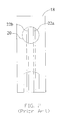
- a US patent No.5366609 disclosed a biotest instrument 10 comprising a display unit 12, a button unit 14, an insertion slot 16 where an electrochemical test strip 18 is inserted, and a plug-in type code card 24 to be plugged in the biotest instrument 10.
- the electrochemical test strip 18 has a test area 20 and a pair of electrodes 22a and 22b connected to the test area 20.
- the code card 24 contains the analysis parameters and operation procedures of the test strip 18.
- the biotest instrument 10 also comprises a controller and a sensor. The controller is coupled to the sensor, the display unit 12, the insert slot 14 and the code card 24. The sensor is coupled to the electrodes 22a and 22b. When the code card 24 is inserted into the biotest instrument 10, the controller reads the analysis parameters and operation procedures inside the code card 24 and controls the sensor to analyze the signal generated by the reaction of a tested liquid on the test area 20 and then outputs the test result to the display unit 12.
- test strips need different code cards in the abovementioned prior art.
- a user has to keep watch for whether a correct code card is inserted into the test instrument. If a wrong code card is inserted, the test result will be incorrect. Therefore, the prior art is inconvenience for users and may give users incorrect information.
- a US patent Publication No. 2007/0068806 disclosed an error-proof test strip, wherein the identification data is built in an identification electrode area of the test strip.
- the identification electrode area is coated with conductive materials with different impedances.
- the test instrument can determine the specification of the test strip according to the impedances of the identification electrodes.
- the identification electrode areas of test strips are coated with different-impedance conductive materials to meet various test requirements, and the test instruments are programmed to meet the intended types of test strips.
- each reaction electrode is cascaded to an identification electrode, and the test instrument needs an additional operational amplifier to implement measuring the impedances of the identification electrodes.
- the conductive materials providing the required impedances have to be determined before fabrication. Therefore, the identification electrode area of the prior art can only be used to differentiate the types of products and customers.
- a US patent Publication No.2007/0068808 disclosed a test strip, wherein a precise resistor is connected to an identification electrode and a reaction electrode via soldering, which increases the complexity and cost of fabrication. Further, the test instrument also needs an additional operational amplifier to implement measuring the impedances, which increases the structural complexity. Besides, the resistor providing the required impedances also has to be determined before fabrication. Therefore, the prior art is limited to only differentiating the types of products and customers.
- Taiwan patent application No. 96100521 disclosed a test strip, wherein the identification electrode area of the test strip has several identification electrodes, and a portion of the identification electrodes are fabricated into open circuit structures according to the required parameters or other conditions to provide different identification signals.
- the number of identification signals will be limited by the number of identification electrodes. When the number of identification electrodes is limited, the identification signals are unlikely to differentiate a lot of customers, many types of test strips, or many types of test instruments.
- the test strip of the present invention has an identification area containing identification electrodes and resistor elements, and the identification area generates digital and analog identification signals, whereby a test strip can incorporate analysis parameters, and whereby a user can fast obtain a correct test result without inserting a code card into a test instrument or inputting a test code or analysis parameters into a test instrument, and whereby the identification area of a test strip has sufficient identification signals to differentiate a lot of customers, many types of test strips, or many types of test instruments.
- the present invention proposes a test strip with an identification function, which comprises a substrate, a test area formed on the substrate and an identification area formed on the substrate.
- the identification area has N pieces of identification electrodes, at least one resistor element, and an electrode area.
- the N pieces of identification electrodes are used to generate digital identification signals, and N ⁇ 2.
- the resistor element is connected in parallel to the identification electrodes and used to generate analog identification signals.
- the electrode area is coupled to the identification electrodes and the resistor element.
- the resistor element may have m sets of resistance values, and m ⁇ 1. Thereby, the identification area can provides m ⁇ 2 N sets of identification signals.
- the test instrument After receiving the identification signal, the test instrument obtains the test code, analysis parameters, expiry date, and/or batch number of the test strip to perform judgment and calibration.
- the present invention proposes a test strip with an identification function and a test instrument using the same, which applies to optical biotest, electrochemical biotest and immunological biotest, and which provides numerous identification signals to differentiate a lot of costumers, many types of test strips and many types of test instruments,
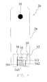
- the test strip in Fig.3 is an optical test strip 26 comprising a substrate 28, an optical test area 30 on one end of the substrate 28 and an identification area 32 on the other end of the substrate 28.
- the identification area 32 has four identification electrodes 341-344, an electrode area and a resistor element 36.
- the four identification electrodes 341-344 generate digital identification signals.
- the electrode area has a ground electrode 38 and a power signal cable 39.
- the four identification electrodes 341-344 are all coupled to the ground electrode 38.
- the resistor element 36 is connected in parallel with the identification electrodes 341-344 and bridges over the ground electrode 38 and the power signal cable 39 to generate an analog identification signal.
- the digital and analog identification signals are used to carry the test code, analysis parameters, expiry date and/or batch number of a test strip.
- the identification electrodes 341-344 and resistor element 36 are preformed on the substrate 28 according to the required analysis parameters or other conditions; for example the resistance value of a printed resistance is selected according to the product type.
- the resistor element 36 is formed via coating on the substrate 28 a resistor paste having a resistance of between 20 ohm and 5M ohm, such as a metal, an alloy, a conductive ink, or a conductive paste (for example, TFR (Thick Film Resistor), a carbon paste, or a carbon paint).
- the identification area 32 is electrically coupled to the test instrument and generates digital identification signals.
- the connection states of the identification electrodes 341-344 and the resistances of the resistor element 36 can create a lot of identification signals.
- At least one of the identification electrodes 341-344 is further fabricated into a open circuit structure with a punching method or a cutting method.
- Each of the identification electrodes 341-344 may be in a circuit-closed or circuit-opened, which can create a digital identification signal of "0" or "1".
- the four identification electrodes 341-344 can totally create 2 4 sets of digital identification signals.
- the four identification electrodes 341-344 shown in Fig.4 generate one set of digital identification signal (0, 1, 0, 0). If the resistor paste has m sets of resistances ranging from 20 to 5M ohm, there will be m sets of analog identification signals corresponding to the m sets of resistances. The combination of the m sets of analog identification signals and the 2 4 sets of digital identification signals will generate m ⁇ 2 4 sets of identification signals totally.
- the test strip in Fig.5 is an electrochemical test strip 40 comprising a substrate 42, an electrochemical test area 44 on one end of the substrate 42 and an identification area 46 on the other end of the substrate 42.
- the identification area 46 has four identification electrodes 481-484, an electrode area and a resistor element 50.
- the four identification electrodes 481-484 generate digital identification signals.
- the electrode area is coupled to the electrochemical test area 44 and has a working electrode 53 and a counter electrode 54.
- the four identification electrodes 481-484 are all coupled to the counter electrode 54.
- the resistor element 50 is connected in parallel with the four identification electrodes 481-484 and bridges over the working electrode 53 and the counter electrode 54 to generate an analog identification signal.
- the digital and analog identification signals are used to carry the test code, analysis parameters, expiry date and/or batch number of a test strip.
- the identification electrodes 481-484 and resistor element 50 are preformed on the substrate 42 according to the required analysis parameters or other conditions; for example the resistance value of a printed resistance is selected according to the product type.
- the resistor element 50 is formed via coating on the substrate 62 a resistor paste having a resistance of between 20 ohm and 5M ohm, such as a metal, an alloy, a conductive ink, or a conductive paste (for example, TFR (Thick Film Resistor), a carbon paste, or a carbon paint).
- a resistor paste having a resistance of between 20 ohm and 5M ohm, such as a metal, an alloy, a conductive ink, or a conductive paste (for example, TFR (Thick Film Resistor), a carbon paste, or a carbon paint).
- At least one of the identification electrodes 481-484 of the electrochemical test strip 40 is further fabricated into an open circuit structure with a punching method or a cutting method. Thereby, the electrochemical test strip 40 can provide a lot of identification signals.
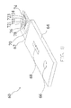
- the test strip in Fig.7 is an immunological test strip 60 comprising a substrate 62, a suction area 66 on the substrate 62, a test area 68 also on the substrate 62, an identification area 70 also on the substrate 62, and a casing 64 encasing a portion of the substrate 62 and revealing the suction area 66, the test area 68 and the identification area 70.
- the test area 68 is a color reaction/colorimetric area.
- the identification area 70 has four identification electrodes 721-724, an electrode area and a resistor element 78. The four identification electrodes 721-724 generate digital identification signals.
- the electrode area has a ground electrode 74 and a power signal cable 76.
- the four identification electrodes 721-724 are all coupled to the ground electrode 74.
- the resistor element 78 is connected in parallel with the identification electrodes 721-724 and bridges over the ground electrode 74 and the power signal cable 76 to generate an analog identification signal.
- the digital and analog identification signals are used to carry the test code, analysis parameters, expiry date and/or batch number of a test strip.
- the identification electrodes 721-724 and the resistor element 78 are preformed on the substrate 62 according to the required analysis parameters or other conditions; for example the resistance value of a printed resistance is selected according to the production type.
- the resistor element 78 is formed via coating on the substrate 62 a resistor paste having a resistance of between 20 ohm and 5M ohm, such as a metal, an alloy, a conductive ink, or a conductive paste (for example, TFR (Thick Film Resistor), a carbon paste, or a carbon paint).
- a resistor paste having a resistance of between 20 ohm and 5M ohm, such as a metal, an alloy, a conductive ink, or a conductive paste (for example, TFR (Thick Film Resistor), a carbon paste, or a carbon paint).
- the immunological test strip 60 After the fabrication and examination of a test strip is completed, at least one of the identification electrodes 721-724 of the immunological test strip 60 is further fabricated into an open circuit structure with a punching method or a cutting method. Thereby, the immunological test strip 60 can provide a lot of identification signals.
- the test instrument 80 of the present invention comprises: a display 82, control buttons 84, a test port 86, and a detector 88.
- the test port 86 is an opening where a test strip is inserted.
- the detector 88 is arranged inside the test instrument and may be an electronic crosspoint connector. When the identification-area side of the test strip is inserted into the test port 86, the identification area is at a position corresponding to the detector 88.
- the detector 88 receives the digital identification signal of the identification electrodes and the analog identification signal of the resistor element and obtains the information of the test code, analysis parameters, expiry date, and/or batch number of the test strip.
- the test instrument also has a microprocessor (not shown in the drawings) used to analyze test data. As the microprocessor is not the feature of the present invention but a conventional device, the technical contents thereof will not be described herein.
- the combinations of the identification electrodes and the resistor element of the present invention can provide many sets of identification signals to differentiate a lot of customers, many types of test strips and many types of test instruments. Therefore, the present invention can solve the problems of insufficient identification signals and unsatisfactory discrimination ability of the prior-art test strips.
- the present invention makes a user able to fast obtain a correct test results without inserting a code card into the test instrument or setting a test code and parameters for a test instrument.
Landscapes
- Health & Medical Sciences (AREA)
- Engineering & Computer Science (AREA)
- Life Sciences & Earth Sciences (AREA)
- Biomedical Technology (AREA)
- Physics & Mathematics (AREA)
- Chemical & Material Sciences (AREA)
- Medicinal Chemistry (AREA)
- General Physics & Mathematics (AREA)
- Molecular Biology (AREA)
- Urology & Nephrology (AREA)
- Optics & Photonics (AREA)
- Food Science & Technology (AREA)
- Hematology (AREA)
- Biochemistry (AREA)
- Biophysics (AREA)
- General Health & Medical Sciences (AREA)
- Analytical Chemistry (AREA)
- Immunology (AREA)
- Pathology (AREA)
- Investigating Or Analyzing Materials By The Use Of Electric Means (AREA)
- Measurement And Recording Of Electrical Phenomena And Electrical Characteristics Of The Living Body (AREA)
Applications Claiming Priority (1)
| Application Number | Priority Date | Filing Date | Title |
|---|---|---|---|
| TW096139142A TW200918896A (en) | 2007-10-19 | 2007-10-19 | Test stripe with identification function and testing device thereof |
Publications (2)
| Publication Number | Publication Date |
|---|---|
| EP2051072A2 true EP2051072A2 (de) | 2009-04-22 |
| EP2051072A3 EP2051072A3 (de) | 2013-10-23 |
Family
ID=40091839
Family Applications (1)
| Application Number | Title | Priority Date | Filing Date |
|---|---|---|---|
| EP08163501.3A Withdrawn EP2051072A3 (de) | 2007-10-19 | 2008-09-02 | Teststreifen-Identifizierungsfunktion und Testinstrument |
Country Status (3)
| Country | Link |
|---|---|
| US (1) | US7625473B2 (de) |
| EP (1) | EP2051072A3 (de) |
| TW (1) | TW200918896A (de) |
Cited By (7)
| Publication number | Priority date | Publication date | Assignee | Title |
|---|---|---|---|---|
| JPS5993161A (ja) * | 1982-11-16 | 1984-05-29 | 松下冷機株式会社 | 冷凍装置 |
| WO2013017218A1 (en) * | 2011-07-29 | 2013-02-07 | Roche Diagnostics Gmbh | Encoded biosensors and methods of manufacture and use thereof |
| CN103308572A (zh) * | 2012-03-12 | 2013-09-18 | 厚美德生物科技股份有限公司 | 具有阵列式接点的检测试片 |
| CN104049009A (zh) * | 2014-06-24 | 2014-09-17 | 杭州必康投资管理有限公司 | 辨认信息装置及生物传感器 |
| WO2016028688A1 (en) * | 2014-08-19 | 2016-02-25 | Bayer Healthcare Llc | Test sensor system and methods for using the same |
| US9754708B2 (en) | 2011-07-29 | 2017-09-05 | Roche Diabetes Care, Inc. | Encoded biosensors and methods of manufacture and use thereof |
| CN107923864A (zh) * | 2015-08-11 | 2018-04-17 | 罗氏糖尿病护理公司 | 编码生物传感器以及其制造和使用方法 |
Families Citing this family (14)
| Publication number | Priority date | Publication date | Assignee | Title |
|---|---|---|---|---|
| US20110057671A1 (en) * | 2009-09-04 | 2011-03-10 | Lifescan Scotland, Ltd. | Methods, system and device to identify a type of test strip |
| TW201116821A (en) * | 2009-11-03 | 2011-05-16 | Hmd Biomedical Inc | Detecting test-piece with double-faced structure and its detecting apparatus |
| CN102072928A (zh) * | 2009-11-20 | 2011-05-25 | 厚美德生物科技股份有限公司 | 双面结构检测试片及其检测装置 |
| CN102236011B (zh) * | 2010-04-30 | 2013-10-16 | 厚美德生物科技股份有限公司 | 具放大镜的生化检测装置 |
| AU2011301843B2 (en) | 2010-09-17 | 2015-02-05 | Agamatrix, Inc. | Method and apparatus for encoding test strips |
| CN102305818A (zh) * | 2011-08-24 | 2012-01-04 | 苏州生物医学工程技术研究所 | 一种电化学生物传感器测量系统 |
| US10168313B2 (en) | 2013-03-15 | 2019-01-01 | Agamatrix, Inc. | Analyte detection meter and associated method of use |
| CN103901079A (zh) * | 2013-12-20 | 2014-07-02 | 杭州世佳电子有限公司 | 具有代码信息的试纸及其制造方法 |
| GB2521481B (en) * | 2013-12-23 | 2016-05-25 | Lifescan Scotland Ltd | Hand-held test meter with an operating range test strip simulation circuit block |
| TWI547695B (zh) * | 2014-11-28 | 2016-09-01 | 宏達國際電子股份有限公司 | 分析裝置與檢測模組 |
| EP3390654A4 (de) * | 2015-12-17 | 2019-07-24 | Polymer Technology Systems, Inc. | Systeme und verfahren für einen vielseitigen elektrochemischen teststreifen, der einen oder mehrere tests für verschiedene analyten in einem teststreifen enthalten kann |
| CN109142484A (zh) * | 2018-07-23 | 2019-01-04 | 青岛厚美德生物科技有限公司 | 一种参数识别元件及免条码生物传感试纸 |
| CN112485301B (zh) * | 2020-11-25 | 2023-07-14 | 三诺生物传感股份有限公司 | 一种电化学测试装置的测试方法、系统、设备及介质 |
| WO2025217370A1 (en) * | 2024-04-10 | 2025-10-16 | University Of Florida Research Foundation, Inc. | Sensor strip with multiple sensors for sensing different agents simultaneously |
Citations (4)
| Publication number | Priority date | Publication date | Assignee | Title |
|---|---|---|---|---|
| US5366609A (en) | 1993-06-08 | 1994-11-22 | Boehringer Mannheim Corporation | Biosensing meter with pluggable memory key |
| TW450997B (en) | 1995-03-27 | 2001-08-21 | Lifescan Inc | Chemical timer a direct-reading reagent test strip |
| US20070068808A1 (en) | 2005-09-28 | 2007-03-29 | Wei-Jung Lee & Yuan-Chen Lee | Blood test chip for blood substance measuring device |
| US20070068806A1 (en) | 2005-09-27 | 2007-03-29 | Health & Life Co., Ltd | Biosensor strip having an identification function and its sensor |
Family Cites Families (8)
| Publication number | Priority date | Publication date | Assignee | Title |
|---|---|---|---|---|
| US4714874A (en) * | 1985-11-12 | 1987-12-22 | Miles Inc. | Test strip identification and instrument calibration |
| JP2002156358A (ja) * | 2000-11-20 | 2002-05-31 | Matsushita Electric Ind Co Ltd | バイオセンサ、通知装置、及び測定装置 |
| US6814844B2 (en) * | 2001-08-29 | 2004-11-09 | Roche Diagnostics Corporation | Biosensor with code pattern |
| JP4264478B2 (ja) * | 2001-09-28 | 2009-05-20 | アークレイ株式会社 | 測定用具および濃度測定装置 |
| US20030204313A1 (en) * | 2002-04-26 | 2003-10-30 | Yao Ou-Yang | Biosensing meter |
| EP1642126A1 (de) * | 2003-06-20 | 2006-04-05 | Roche Diagnostics GmbH | System und verfahren zur codierung von informationen auf einem biosensor-teststreifen |
| US7601299B2 (en) * | 2004-06-18 | 2009-10-13 | Roche Diagnostics Operations, Inc. | System and method for coding information on a biosensor test strip |
| US7418285B2 (en) * | 2004-12-29 | 2008-08-26 | Abbott Laboratories | Analyte test sensor and method of manufacturing the same |
-
2007
- 2007-10-19 TW TW096139142A patent/TW200918896A/zh not_active IP Right Cessation
-
2008
- 2008-08-22 US US12/196,727 patent/US7625473B2/en active Active
- 2008-09-02 EP EP08163501.3A patent/EP2051072A3/de not_active Withdrawn
Patent Citations (4)
| Publication number | Priority date | Publication date | Assignee | Title |
|---|---|---|---|---|
| US5366609A (en) | 1993-06-08 | 1994-11-22 | Boehringer Mannheim Corporation | Biosensing meter with pluggable memory key |
| TW450997B (en) | 1995-03-27 | 2001-08-21 | Lifescan Inc | Chemical timer a direct-reading reagent test strip |
| US20070068806A1 (en) | 2005-09-27 | 2007-03-29 | Health & Life Co., Ltd | Biosensor strip having an identification function and its sensor |
| US20070068808A1 (en) | 2005-09-28 | 2007-03-29 | Wei-Jung Lee & Yuan-Chen Lee | Blood test chip for blood substance measuring device |
Cited By (18)
| Publication number | Priority date | Publication date | Assignee | Title |
|---|---|---|---|---|
| JPS5993161A (ja) * | 1982-11-16 | 1984-05-29 | 松下冷機株式会社 | 冷凍装置 |
| CN103733056B (zh) * | 2011-07-29 | 2016-11-16 | 霍夫曼-拉罗奇有限公司 | 编码生物传感器以及其制造和使用方法 |
| JP2017181523A (ja) * | 2011-07-29 | 2017-10-05 | エフ ホフマン−ラ ロッシュ アクチェン ゲゼルシャフト | エンコードされたバイオセンサーならびにそれを製造するおよび使用するための方法 |
| KR20140042887A (ko) * | 2011-07-29 | 2014-04-07 | 에프. 호프만-라 로슈 아게 | 인코딩된 바이오센서들과 그 제조 및 사용 방법들 |
| CN103733056A (zh) * | 2011-07-29 | 2014-04-16 | 霍夫曼-拉罗奇有限公司 | 编码生物传感器以及其制造和使用方法 |
| JP2014521943A (ja) * | 2011-07-29 | 2014-08-28 | エフ ホフマン−ラ ロッシュ アクチェン ゲゼルシャフト | エンコードされたバイオセンサーならびにそれを製造するおよび使用するための方法 |
| KR20160060151A (ko) * | 2011-07-29 | 2016-05-27 | 에프. 호프만-라 로슈 아게 | 인코딩된 바이오센서들과 그 제조 및 사용 방법들 |
| US8888973B2 (en) | 2011-07-29 | 2014-11-18 | Roche Diagnostics Operations, Inc. | Encoded biosensors and methods of manufacture and use thereof |
| EP4141433A1 (de) * | 2011-07-29 | 2023-03-01 | Roche Diabetes Care GmbH | Codierte biosensoren und verfahren zur herstellung und verwendung davon |
| US9267911B2 (en) | 2011-07-29 | 2016-02-23 | Roche Diabetes Care, Inc. | Encoded biosensors and methods of manufacture and use thereof |
| WO2013017218A1 (en) * | 2011-07-29 | 2013-02-07 | Roche Diagnostics Gmbh | Encoded biosensors and methods of manufacture and use thereof |
| US9754708B2 (en) | 2011-07-29 | 2017-09-05 | Roche Diabetes Care, Inc. | Encoded biosensors and methods of manufacture and use thereof |
| CN103308572B (zh) * | 2012-03-12 | 2015-08-26 | 厚美德生物科技股份有限公司 | 具有阵列式接点的检测试片 |
| CN103308572A (zh) * | 2012-03-12 | 2013-09-18 | 厚美德生物科技股份有限公司 | 具有阵列式接点的检测试片 |
| CN104049009A (zh) * | 2014-06-24 | 2014-09-17 | 杭州必康投资管理有限公司 | 辨认信息装置及生物传感器 |
| WO2016028688A1 (en) * | 2014-08-19 | 2016-02-25 | Bayer Healthcare Llc | Test sensor system and methods for using the same |
| CN107923864A (zh) * | 2015-08-11 | 2018-04-17 | 罗氏糖尿病护理公司 | 编码生物传感器以及其制造和使用方法 |
| CN107923864B (zh) * | 2015-08-11 | 2020-08-18 | 罗氏糖尿病护理公司 | 编码生物传感器以及其制造和使用方法 |
Also Published As
| Publication number | Publication date |
|---|---|
| TW200918896A (en) | 2009-05-01 |
| EP2051072A3 (de) | 2013-10-23 |
| US20090101500A1 (en) | 2009-04-23 |
| TWI361892B (de) | 2012-04-11 |
| US7625473B2 (en) | 2009-12-01 |
Similar Documents
| Publication | Publication Date | Title |
|---|---|---|
| US7625473B2 (en) | Test strip with identification function and test instrument using the same | |
| CN101430327B (zh) | 具识别功能的检测试片及其检测装置 | |
| US6377894B1 (en) | Analyte test instrument having improved calibration and communication processes | |
| US7776559B2 (en) | Disposable blood test device | |
| EP2171439B1 (de) | System zur kalibrierung eines biosensors | |
| US20030111357A1 (en) | Test meter calibration | |
| WO2003050534A1 (en) | Test meter calibration | |
| US20100015006A1 (en) | Test strip with identification openings and test instrument using the same | |
| JP2010525353A (ja) | 電気化学的測定用のストリップ | |
| JP2011502263A (ja) | 液体サンプル中の被分析物の濃度を測定するテストストリップ及びシステム | |
| KR19990082866A (ko) | 의료용 분석기의 데이터 관리 인증을 위한 방법과 장치 | |
| US20110102152A1 (en) | Double side identification notation-containing test strip and test instrument thereof | |
| EP2616802B1 (de) | Verfahren und vorrichtung zur codierung von teststreifen | |
| TWI412740B (zh) | 檢測試片、生化感測系統、及量測裝置 | |
| US7514040B2 (en) | Intelligent biosensing meter | |
| CN101661033A (zh) | 检测试片、生化感测系统、及量测装置 | |
| CN102072928A (zh) | 双面结构检测试片及其检测装置 | |
| CN102023180B (zh) | 生化传感系统、测量装置、生化传感试片及其制造方法 | |
| CN105358060B (zh) | 使用操作范围配置技术的分析物仪表 | |
| CN103105413B (zh) | 生物感测器以及生物测量系统 | |
| US20060040251A1 (en) | Portable medical measurement device and method | |
| EP4239328B1 (de) | Testgerät und messvorrichtung | |
| TWM334326U (en) | Socket for receiving test strip | |
| JP3117358U (ja) | 識別機能を有する生物計測器試験片及びその計測器 | |
| JP2005147688A (ja) | 濃度測定器の機能切替方法 |
Legal Events
| Date | Code | Title | Description |
|---|---|---|---|
| PUAI | Public reference made under article 153(3) epc to a published international application that has entered the european phase |
Free format text: ORIGINAL CODE: 0009012 |
|
| 17P | Request for examination filed |
Effective date: 20080902 |
|
| AK | Designated contracting states |
Kind code of ref document: A2 Designated state(s): AT BE BG CH CY CZ DE DK EE ES FI FR GB GR HR HU IE IS IT LI LT LU LV MC MT NL NO PL PT RO SE SI SK TR |
|
| AX | Request for extension of the european patent |
Extension state: AL BA MK RS |
|
| PUAL | Search report despatched |
Free format text: ORIGINAL CODE: 0009013 |
|
| AK | Designated contracting states |
Kind code of ref document: A3 Designated state(s): AT BE BG CH CY CZ DE DK EE ES FI FR GB GR HR HU IE IS IT LI LT LU LV MC MT NL NO PL PT RO SE SI SK TR |
|
| AX | Request for extension of the european patent |
Extension state: AL BA MK RS |
|
| RIC1 | Information provided on ipc code assigned before grant |
Ipc: G01N 33/487 20060101AFI20130917BHEP |
|
| AKX | Designation fees paid |
Designated state(s): AT BE BG CH CY CZ DE DK EE ES FI FR GB GR HR HU IE IS IT LI LT LU LV MC MT NL NO PL PT RO SE SI SK TR |
|
| 17Q | First examination report despatched |
Effective date: 20151015 |
|
| STAA | Information on the status of an ep patent application or granted ep patent |
Free format text: STATUS: THE APPLICATION IS DEEMED TO BE WITHDRAWN |
|
| 18D | Application deemed to be withdrawn |
Effective date: 20160226 |