EP2051191A1 - Système RFID capable de détecter l'orientation d'une étiquette RFID, étiquette RFID correspondante, et système de puzzle utilisant le système RFID - Google Patents
Système RFID capable de détecter l'orientation d'une étiquette RFID, étiquette RFID correspondante, et système de puzzle utilisant le système RFID Download PDFInfo
- Publication number
- EP2051191A1 EP2051191A1 EP08166947A EP08166947A EP2051191A1 EP 2051191 A1 EP2051191 A1 EP 2051191A1 EP 08166947 A EP08166947 A EP 08166947A EP 08166947 A EP08166947 A EP 08166947A EP 2051191 A1 EP2051191 A1 EP 2051191A1
- Authority
- EP
- European Patent Office
- Prior art keywords
- rfid tag
- identification data
- signal
- rfid
- antennas
- Prior art date
- Legal status (The legal status is an assumption and is not a legal conclusion. Google has not performed a legal analysis and makes no representation as to the accuracy of the status listed.)
- Withdrawn
Links
Images


Classifications
-
- G—PHYSICS
- G06—COMPUTING OR CALCULATING; COUNTING
- G06K—GRAPHICAL DATA READING; PRESENTATION OF DATA; RECORD CARRIERS; HANDLING RECORD CARRIERS
- G06K19/00—Record carriers for use with machines and with at least a part designed to carry digital markings
- G06K19/06—Record carriers for use with machines and with at least a part designed to carry digital markings characterised by the kind of the digital marking, e.g. shape, nature, code
- G06K19/067—Record carriers with conductive marks, printed circuits or semiconductor circuit elements, e.g. credit or identity cards also with resonating or responding marks without active components
- G06K19/07—Record carriers with conductive marks, printed circuits or semiconductor circuit elements, e.g. credit or identity cards also with resonating or responding marks without active components with integrated circuit chips
- G06K19/077—Constructional details, e.g. mounting of circuits in the carrier
- G06K19/07749—Constructional details, e.g. mounting of circuits in the carrier the record carrier being capable of non-contact communication, e.g. constructional details of the antenna of a non-contact smart card
-
- A—HUMAN NECESSITIES
- A63—SPORTS; GAMES; AMUSEMENTS
- A63F—CARD, BOARD, OR ROULETTE GAMES; INDOOR GAMES USING SMALL MOVING PLAYING BODIES; VIDEO GAMES; GAMES NOT OTHERWISE PROVIDED FOR
- A63F9/00—Games not otherwise provided for
- A63F9/06—Patience; Other games for self-amusement
- A63F9/10—Two-dimensional [2D] jig-saw puzzles
-
- A—HUMAN NECESSITIES
- A63—SPORTS; GAMES; AMUSEMENTS
- A63F—CARD, BOARD, OR ROULETTE GAMES; INDOOR GAMES USING SMALL MOVING PLAYING BODIES; VIDEO GAMES; GAMES NOT OTHERWISE PROVIDED FOR
- A63F9/00—Games not otherwise provided for
- A63F9/06—Patience; Other games for self-amusement
- A63F9/12—Three-dimensional [3D] jig-saw puzzles
- A63F9/1204—Puzzles consisting of non-interlocking identical blocks, e.g. children's block puzzles
-
- G—PHYSICS
- G06—COMPUTING OR CALCULATING; COUNTING
- G06K—GRAPHICAL DATA READING; PRESENTATION OF DATA; RECORD CARRIERS; HANDLING RECORD CARRIERS
- G06K19/00—Record carriers for use with machines and with at least a part designed to carry digital markings
- G06K19/06—Record carriers for use with machines and with at least a part designed to carry digital markings characterised by the kind of the digital marking, e.g. shape, nature, code
- G06K19/067—Record carriers with conductive marks, printed circuits or semiconductor circuit elements, e.g. credit or identity cards also with resonating or responding marks without active components
- G06K19/07—Record carriers with conductive marks, printed circuits or semiconductor circuit elements, e.g. credit or identity cards also with resonating or responding marks without active components with integrated circuit chips
- G06K19/077—Constructional details, e.g. mounting of circuits in the carrier
- G06K19/07749—Constructional details, e.g. mounting of circuits in the carrier the record carrier being capable of non-contact communication, e.g. constructional details of the antenna of a non-contact smart card
- G06K19/07766—Constructional details, e.g. mounting of circuits in the carrier the record carrier being capable of non-contact communication, e.g. constructional details of the antenna of a non-contact smart card comprising at least a second communication arrangement in addition to a first non-contact communication arrangement
- G06K19/07767—Constructional details, e.g. mounting of circuits in the carrier the record carrier being capable of non-contact communication, e.g. constructional details of the antenna of a non-contact smart card comprising at least a second communication arrangement in addition to a first non-contact communication arrangement the first and second communication means being two different antennas types, e.g. dipole and coil type, or two antennas of the same kind but operating at different frequencies
-
- A—HUMAN NECESSITIES
- A63—SPORTS; GAMES; AMUSEMENTS
- A63F—CARD, BOARD, OR ROULETTE GAMES; INDOOR GAMES USING SMALL MOVING PLAYING BODIES; VIDEO GAMES; GAMES NOT OTHERWISE PROVIDED FOR
- A63F9/00—Games not otherwise provided for
- A63F9/06—Patience; Other games for self-amusement
- A63F9/10—Two-dimensional [2D] jig-saw puzzles
- A63F2009/1061—Two-dimensional [2D] jig-saw puzzles with electric features, e.g. light, wires
-
- A—HUMAN NECESSITIES
- A63—SPORTS; GAMES; AMUSEMENTS
- A63F—CARD, BOARD, OR ROULETTE GAMES; INDOOR GAMES USING SMALL MOVING PLAYING BODIES; VIDEO GAMES; GAMES NOT OTHERWISE PROVIDED FOR
- A63F9/00—Games not otherwise provided for
- A63F9/24—Games using electronic circuits not otherwise provided for
- A63F2009/2483—Other characteristics
- A63F2009/2488—Remotely playable
- A63F2009/2489—Remotely playable by radio transmitters, e.g. using RFID
Definitions
- the present invention relates to a radio-frequency identification (RFID) system, and more particularly to an RFID system having an RFID tag provided with a plurality of antennas and accordingly, being capable of detecting an orientation of the RFID tag.
- RFID radio-frequency identification
- the present invention also relates to an RFID tag enabling an RFID system to detect its orientation, and a puzzle system using the RFID system capable of detecting an RFID tag orientation.
- a radio-frequency identification (RFID) tag has the advantages of not requiring an internally built power source, and being lightweight, compact, and wirelessly inducible. With these advantages, the RFID tag has been widely applied to many different fields, comprising warehouse management, logistics, induction-type control, etc.
- a conventional reader can only detect the existence of the RFID tag. That is, when the RFID tag receives an RF signal transmitted from the reader, the RFID tag can correspondingly generate an amount of electric power and wirelessly sends out an identification data thereof.
- the reader is able to know there is an RFID tag nearby the reader. From the received identification data, the reader is also able to retrieve data about the object having the RFID tag attached thereto.
- none of the currently available RFID tags allows the reader to detect an orientation of the RFID tag. Therefore, the application of the RFID tags is still largely limited.
- the RFID tag comprises a plurality of antennas, a plurality of power receiving modules, and a wireless communication module.
- the plurality of antennas independently receives an RF signal each, and the plurality of power receiving modules are correspondingly connected to the plurality of antennas.
- One of the power receiving modules will output an electric power according to an RF signal received by an antenna corresponding thereto.
- the wireless communication module is electrically connected to the plurality of power receiving modules. After receiving the electric power generated by the power receiving module, the wireless communication module determines an identification data that is corresponding to the antenna receiving the RF signal, and sends out the identification data via at least one of the plurality of antennas.
- An RFID tag comprises a memory, a plurality of antennas, a plurality of power receiving modules, a logic circuit, a control circuit, and a modulation circuit
- the memory stores a first identification data.
- the plurality of antenna independently receives an RF signal each.
- the plurality of power receiving modules are correspondingly connected to the plurality of antennas. According to an RF signal received by an antenna corresponding thereto, one of' the power receiving modules outputs an electric power for operation of the RFID.
- the logic circuit is electrically connected to the plurality of power receiving modules to generate a position data corresponding to the antenna receiving the RF signal,
- the control circuit combines the first identification data with the position data to generate a second identification data.
- the modulation circuit modulates the second identification data to generate a modulation signal, which is then sent out via at least one of the antennas.
- the RFID system capable of detecting RFID tag orientation comprises at least one RFID tag, such as any one of that having been described above, a reader, and a processor,
- the RFID tag receives an RF signal transmitted from the reader and diligently outputs an identification data, which is received by the reader. Based on the identification data received by the reader, the processor can determine an orientation of the RFID tag.
- a puzzle system can be designed by employing the RFID system and the RFID tag of the present invention.
- Puzzle system according to a preferred embodiment of the present invention, comprises a platform, a plurality of puzzle pieces, a reader, and processor.
- Each of the puzzle pieces is provided with at least one of the above-described RFID tags for receiving an RF signal transmitted from the reader and wirelessly outputting an identification data, which is received by the reader.
- the processor determines an orientation of the RFID tag. Then, based on the orientation of the RFID tag, the processor further determines whether the puzzle pieces are correctly positioned on the platform.
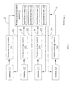
- Fig. 1 is a general block diagram of an RFID tag according to the present invention
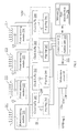
- Fig. 2 is a block diagram of an RFID tag according to a first embodiment of the present invention.
- Fig. 3 is a block diagram of an RFID tag according to a second embodiment of the present invention.
- Fig. 4 is a block diagram of' an RFID system capable of detecting RFID tag orientation according to the present invention.
- Fig. 5 schematically shows the arrangement of an RFID tag of the present invention on a planar object
- Fig. 6 schematically shows the arrangement of an RFID tag of the present invention on a three-dimensional object
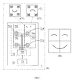
- Fig. 7 schematically shows a puzzle system employing the RFID system of the present invention.
- Exemplary embodiments of the present invention are described herein in the context of an RFID system and an RFID tag thereof, and a puzzle system using the same.
- Fig. 1 illustrates a general block diagram of a radio-frequency identification (RFID) tag according to the present invention
- the RFID tag 1 comprises a plurality of antennas 111 ⁇ 114, a plurality of power receiving modules 121 ⁇ 124, and a wireless communication module 13
- the power receiving modules 121 ⁇ 124 are in a one-to-one correspondence to the antennas 111 ⁇ 114
- the power receiving module corresponding to that antenna outputs an amount of electric power 14 based on the received RF signal.
- the power receiving module 121 will generate electric power.
- the power receiving modules each comprise an RF-to-DC (direct current) circuit, and can, depending on actual need, further comprise a DC limiting circuit.
- the wireless communication module 13 is electrically connected to the power receiving modules 121 ⁇ 124.
- the wireless communication module 13 determines an identification data that is corresponding to the antenna receiving the RF signal, and sends out the identification data via the antenna receiving the RF signal. For instance, when the antenna 111 receives an RF signal, the power receiving module 121 generates electric power 14 and supplies the same to the wireless communication module 13.
- the wireless communication module 13 outputs an identification data 151 that is corresponding to the antenna 111, and the identification data 151 is wirelessly sent out via the antenna 111 Similarly, when the antenna 112, 113 or 114 receives an RF signal, the corresponding power receiving module 122, 123 or 124 will generate electric power 14, so that the wireless communication module 13 outputs the identification data 152, 153 or 154 corresponding to the antenna 112, 113 or 114.
- the antennas are preferably arranged to be orthogonal to one another or be spaced from one another by a predetermined distance, so that only one of the antennas can receive the RF signal at the same time point. In this manner, it is able to determine which antenna has received the RF signal by recognizing the identification data sent out by the RFID tag 1. If the antennas are arranged at different positions on a planar object or on different faces of a three-dimensional (3D) object, it is possible to further determine how the planar object or the 3D object is positioned.
- Fig. 1 there are shown four antennas and four power receiving modules only for purpose of exemplification. It is understood, the number of the antennas and of the power receiving modules is not limited to four, but may be any other quantity.
- Fig. 2 illustrates a block diagram of an RFID tag according to a first embodiment of the present invention.
- the RFID tag 2 comprises a memory 23, a plurality of antennas 211 ⁇ 214, a plurality of power receiving modules 221 ⁇ 224, a logic circuit 24, a control circuit 25, and a modulation circuit 26.
- the memory 23 is used to store a first identification data 231, and the power receiving modules 221 ⁇ 224 are correspondingly connected to the antennas 211 ⁇ 214.
- the power receiving module corresponding to that antenna will output electric power VDD according to the received RF signal for operation of all the components in the RFID tag 2
- the logic circuit 24 comprises a plurality of clock buffers 241 ⁇ 244, and a plurality of flip-flops 245 ⁇ 248
- the clock buffers 241 ⁇ 244 each are correspondingly connected to an end of the antennas 211 ⁇ 244 to generate a clock 249 according to a voltage signal at the end of the corresponding antenna, and the generated clock 249 is used by the memory 23, the control circuit 25, and the modulation circuit 26 for them to operate.
- the flip-flops 245 ⁇ 248 are correspondingly connected to the clock buffers 241 ⁇ 244 respectively, and the outputs of the flip-flops 245 ⁇ 248 are electrically connected to the control circuit 25.
- Inputs of the flip-flops 245 ⁇ 248 are electrically connected to the power supply VDD.
- the flip-flops 245 ⁇ 248 are reset, so that the outputs of the flip-flops 245 ⁇ 248 are set to logic zero (0).
- the flip-flops 245 ⁇ 248 are correspondingly connected to the clock buffers 241 ⁇ 244, the flip-flops 245 ⁇ 248 can be triggered by the output signals of the clock buffers 241 ⁇ 244, so that the voltage VDD at the inputs of the flip-flops 245 ⁇ 248 is allowed to be transmitted to the outputs of the flip-flops 245 ⁇ 248 Therefore, for other antennas that do not receive an RF signal, the clock buffers corresponding thereto will not generate any clock or any trigger signal, and outputs of the flip-flops corresponding thereto will maintain at the reset state, that is, logic 0.
- the control circuit 25 can determine a position data 251 corresponding to the antenna receiving the RF signal. For instance, when the antenna 211, 212, 213 or 214 receives an RF signal, the position data 251 will be "D001", “0010", "0100” or "1000". Depending on actual need, the control circuit 25 can further comprise a register to store the position data 251.
- the control circuit 25 can determine the position data 251 and read the first identification data 231 from the memory 23, and then combines the first identification data 231 with the position data 251 to generate a second identification data 252. For example, when the first identification data 231 is "1101111" and the position data 251 is "0010", the second identification data 252 shall be "00101101111".
- the modulation circuit 26 is electrically connected to the control circuit 25 and to an end of each of the antennas 211 ⁇ 214.
- the modulation circuit 26 modulates the second identification data 252 to generate a modulation signal, which is then wirelessly sent out via the antennas 211 ⁇ 214.
- the modulation signal is sent out via the antenna corresponding to the position data 251.
- the RFID tag 2 can further comprise a power management circuit, such as a charge pump circuit, to raise the voltage value of the electric power output by the power receiving modules 221 ⁇ 224.
- a power management circuit such as a charge pump circuit
- the power receiving modules each comprise an RF-to-DC circuit, and, depending on actual need, can further comprise a DC limiting circuit.
- the DC limiting circuit preferably comprises a voltage stabilizer and an RF protection circuit.
- Fig. 3 illustrates a block diagram of an RFID tag 3 according to a second embodiment of the present invention.
- the RFID tag 3 comprises a memory 33, a plurality of antennas 311 ⁇ 314, a plurality of RF-to-DC rectifiers 321 ⁇ 324, a plurality of buffers 341 ⁇ 344, a control circuit 35, a voltage stabilizer 391, a charge pump circuit 392, and a modulation circuit 36
- the memory 33 has a plurality of identification data 331 ⁇ 334 stored thereon, and the identification data 331 ⁇ 334 are in a one-to-one correspondence to the antennas 311 ⁇ 314
- the RF-to-DC rectifiers 321 ⁇ 324 are electrically connected to the antennas 311 ⁇ 314, respectively. Based on an RF signal received by the antenna, the RF-to-DC rectifier corresponding to that antenna generates electric power VDD, which is supplied to other components of the RFID tag 3 for operation.
- the voltage stabilizer 391 can further stabilize the electric power VDD.
- the buffers 341 ⁇ 344 are electrically connected to an end of the antennas 311 ⁇ 314, respectively, and outputs of the buffers 341 ⁇ 344 are electrically connected to the control circuit 35.
- the control circuit 35 can determine which one of the antennas has received an RF signal and then reads an identification data that is corresponding to that antenna from the memory 33. The read identification data is then output to the modulation circuit 36. For instance, when the antenna 311 receives an RF signal, the control circuit 35 reads the identification data 331; or, when the antenna 312 receives an RF signal, the control circuit 35 will read the identification data 332. Thereafter, the modulation circuit 36 modulates the identification data to generate a modulation signal, which is wirelessly sent out via the antennas 311 ⁇ 314. Preferably, the modulation signal is sent out via the antenna that is corresponding to the identification data
- Fig. 4 illustrates a block diagram of an RFID system capable of detecting RFID tag orientation according to the present invention.
- the RFID system 4 comprises at least one RFID tag 49, a reader 40, and a processor 44.
- the RFID tag 49 has a plurality of antennas. When a particular one of the antennas receives an RF signal, the RFID tag 49 would wirelessly send out a specific identification data corresponding to that antenna.
- the RFID tag 49 can be any of the RFID tags shown in Figs. 1 , 2 and 3 , and is not repeatedly described in detail herein.
- the reader 40 comprises a carrier generation circuit 41, a transmission antenna 42, and a detection circuit 43.
- the carrier generation circuit 41 is used to generate a carrier, which has a time-varying current which then pass the transmission antenna 42 to emit an RF signal 421, After receiving the RF signal 421, the RFID tag 49 correspondingly transmits a wireless signal 422 containing an identification data 431.
- the detection circuit 43 receives the wireless signal 422 via the transmission antenna 42, and retrieves the identification data 431 from the wireless data 422. Since the identification data 431 corresponds to the antenna of the RFID tag 49 that receives the RF signal 421, the processor 44 can determine the orientation of the RFID tag 49 according to the identification data 431.
- Fig. 5 schematically illustrates the arrangement of a RFID tag of the present invention on a planar object.
- the RFID tag is arranged on a planar object 50, and comprises four antennas 511 ⁇ 514 and a chip 52. Except for the antennas, all other related circuits, such as the logic circuit, the memory, the control circuit, the RF-to-DC rectifiers, etc , that have been mentioned in the above-described RFID tag embodiments are provided on the chip 52.
- the antennas 511 ⁇ 514 are separately arranged at four different corners of the planar object 50. Therefore, the orientation of the RFID tag can indicate how the planar object 50 is positioned.
- Fig. 6 schematically illustrates the arrangement of a RFID tag of the present invention on a three-dimensional (3D) object
- the RFID tag is arranged on a cuboidal object 60, and comprises six antennas 611 ⁇ 616 and a chip 62 Since the chip 62 is functionally similar to the chip 52, it is not repeatedly discussed herein.
- the antennas 611 ⁇ 616 are separately arranged on six different faces of the cuboidal object 60. Therefore, the orientation of the RFID tag can indicate how the cuboidal object 60 is positioned.
- the manner in which the object is position can determine which one of the antennas will receive the RF signal transmitted from the reader. Since the RFID tag of the present invention can send out identification data corresponding to the antenna that receives the RF signal, the processor of the RFID system of the present invention is able to determine how the object is positioned according to the identification data received from the RFID tag. If the object is provided with a pattern that is meaningful only when the object is positioned to orient toward a specific direction, the RFID system of the present invention can be applied to a large number of different fields.
- the object when a puzzle pattern is provided on an object, the object can be used as a puzzle piece, and the RFID system can be implemented as a puzzle system.
- the object when a plurality of learning patterns or designs is provided on an object, the object can be used as a multifunctional learning card, and the RFID system can be implemented as an induction-type learning system
- Fig. 7 schematically illustrates a puzzle system employing the RFID system of the present invention.
- part (A) illustrates a puzzle system 7
- part (B) illustrates the puzzle system with puzzle pieces thereof having been arranged at correct locations and in correct orientation.
- the puzzle system 7 comprises a platform 70, a plurality of puzzle pieces 71, a reader 72, and a processor 73.
- On the platform 70 there is defined a plurality of zones 701 ⁇ 704, on each of which, one of the puzzle pieces 71 can be movably laid.
- the reader 72 has a plurality of transmission antennas 721 ⁇ 724 being separately arranged on the zones 701 ⁇ 704,
- the reader 72 and the processor 73 are preferably provided inside the platform 70, Since each of the puzzle pieces 71 is provided at four corners with an antenna each, the processor 73 can determine how the puzzle pieces 71 are positioned or oriented in each of the zones 701 ⁇ 704.
- parts (C1) and (C2) in Fig. 7 show two different ways of positioning a puzzle piece 71 Since the puzzle piece 71 has a puzzle pattern provided thereon, the puzzle piece 71 must be correctly laid in one zone and correctly oriented to complete a puzzle game.
- the reader 72 comprises a detection circuit 725 for reading identification data received by the transmission antennas 721 ⁇ 724, and the processor 73 can determine whether the puzzle pieces 71 are correctly laid in the zones 701 ⁇ 704 according to the received identification data.
Landscapes
- Engineering & Computer Science (AREA)
- Computer Hardware Design (AREA)
- Microelectronics & Electronic Packaging (AREA)
- Physics & Mathematics (AREA)
- General Physics & Mathematics (AREA)
- Theoretical Computer Science (AREA)
- Multimedia (AREA)
- Near-Field Transmission Systems (AREA)
- Radar Systems Or Details Thereof (AREA)
- Credit Cards Or The Like (AREA)
- Toys (AREA)
Applications Claiming Priority (1)
| Application Number | Priority Date | Filing Date | Title |
|---|---|---|---|
| US96087207P | 2007-10-18 | 2007-10-18 |
Publications (1)
| Publication Number | Publication Date |
|---|---|
| EP2051191A1 true EP2051191A1 (fr) | 2009-04-22 |
Family
ID=40194037
Family Applications (1)
| Application Number | Title | Priority Date | Filing Date |
|---|---|---|---|
| EP08166947A Withdrawn EP2051191A1 (fr) | 2007-10-18 | 2008-10-17 | Système RFID capable de détecter l'orientation d'une étiquette RFID, étiquette RFID correspondante, et système de puzzle utilisant le système RFID |
Country Status (5)
| Country | Link |
|---|---|
| US (1) | US20090102120A1 (fr) |
| EP (1) | EP2051191A1 (fr) |
| JP (1) | JP2009095680A (fr) |
| CN (1) | CN101414364A (fr) |
| TW (1) | TW200919324A (fr) |
Cited By (1)
| Publication number | Priority date | Publication date | Assignee | Title |
|---|---|---|---|---|
| CN104841143A (zh) * | 2015-02-12 | 2015-08-19 | 广东奥飞动漫文化股份有限公司 | 一种感应电动玩具 |
Families Citing this family (21)
| Publication number | Priority date | Publication date | Assignee | Title |
|---|---|---|---|---|
| US20090117872A1 (en) * | 2007-11-05 | 2009-05-07 | Jorgenson Joel A | Passively powered element with multiple energy harvesting and communication channels |
| TWI385581B (zh) * | 2008-10-27 | 2013-02-11 | Univ Nat Taiwan Science Tech | 被動式標籤及射頻識別系統 |
| JP5327171B2 (ja) * | 2010-09-15 | 2013-10-30 | オムロン株式会社 | Rfidシステム |
| US20120223818A1 (en) * | 2011-03-03 | 2012-09-06 | Sino Matrix Technology, Inc. | Data random selection device |
| US10013588B2 (en) * | 2011-08-17 | 2018-07-03 | Hand Held Products, Inc. | Encoded information reading terminal with multi-directional antenna |
| US8888100B2 (en) | 2011-11-16 | 2014-11-18 | Mattel, Inc. | Electronic toy |
| FR2991800B1 (fr) * | 2012-06-07 | 2014-07-04 | Epawn | Dispositif d'aide a la localisation en temps reel d'un element mobile autoalimente |
| US9776071B2 (en) | 2013-05-09 | 2017-10-03 | Mattel, Inc. | Resonant coils for use with games and toys |
| TWI643435B (zh) * | 2013-08-21 | 2018-12-01 | 日商半導體能源研究所股份有限公司 | 電荷泵電路以及具備電荷泵電路的半導體裝置 |
| KR102267237B1 (ko) | 2014-03-07 | 2021-06-18 | 가부시키가이샤 한도오따이 에네루기 켄큐쇼 | 반도체 장치 및 전자 기기 |
| US9312280B2 (en) | 2014-07-25 | 2016-04-12 | Semiconductor Energy Laboratory Co., Ltd. | Semiconductor device |
| KR101526508B1 (ko) * | 2014-12-03 | 2015-06-09 | 엠텍씨앤케이주식회사 | 외부 기기와 연동하는 퍼즐 시스템 |
| US10311264B1 (en) * | 2018-04-30 | 2019-06-04 | Xerox Corporation | Printed RFID tag antenna array with interfering subarrays |
| CN108646217A (zh) * | 2018-07-10 | 2018-10-12 | 宜兴启明星物联技术有限公司 | 一种利用rfid技术实现室内精准定位的系统 |
| US11100514B2 (en) | 2018-10-11 | 2021-08-24 | International Business Machines Corporation | Authentication system for payment cards |
| EP3917635B1 (fr) * | 2019-01-31 | 2025-07-02 | Lego A/S | Système de construction de jouet modulaire avec des éléments de construction electroniques |
| CN110333482B (zh) * | 2019-06-19 | 2023-10-10 | 深圳数联天下智能科技有限公司 | 物体放置状态的确定方法及相关装置 |
| CN110237524B (zh) * | 2019-06-19 | 2023-06-02 | 深圳数联天下智能科技有限公司 | 物体摆放图形的确定方法及相关装置 |
| TWI736043B (zh) * | 2019-11-29 | 2021-08-11 | 財團法人金屬工業研究發展中心 | 多目標射頻定位系統、定位方法及初始距離量測方法 |
| US20230381637A1 (en) * | 2022-05-26 | 2023-11-30 | Kamil Podhola | Chip board system |
| US20250272519A1 (en) * | 2024-02-28 | 2025-08-28 | Comcast Cable Communications, Llc | RFID Tag Capable of Variable Information Based on Orientation |
Citations (4)
| Publication number | Priority date | Publication date | Assignee | Title |
|---|---|---|---|---|
| WO2002011062A1 (fr) * | 2000-07-28 | 2002-02-07 | Inside Technologies | Etiquette electronique sans contact pour objet tridimensionnel |
| DE102006009802A1 (de) * | 2005-10-14 | 2007-04-19 | Toni Dick | RFID-Transponder mit mindestens zwei Antennen |
| US20080074270A1 (en) * | 2006-09-22 | 2008-03-27 | Nortel Networks Limited | Three dimensional RF signatures |
| EP2011553A1 (fr) * | 2007-07-03 | 2009-01-07 | G-Time Electronic Co., Ltd. | Système de jeu et procédé pour y jouer |
Family Cites Families (8)
| Publication number | Priority date | Publication date | Assignee | Title |
|---|---|---|---|---|
| IL121666A (en) * | 1997-08-31 | 2001-03-19 | Bronfeld Joshua | Electronic dice |
| US7005968B1 (en) * | 2000-06-07 | 2006-02-28 | Symbol Technologies, Inc. | Wireless locating and tracking systems |
| JP2002248258A (ja) * | 2001-02-26 | 2002-09-03 | Teizu Design Company:Kk | 磁石とリードスイッチを利用したパズル |
| JP2002320763A (ja) * | 2001-04-26 | 2002-11-05 | Toppan Forms Co Ltd | Icタグが内蔵された多面体及びこれを利用したゲーム装置 |
| JP2005234871A (ja) * | 2004-02-19 | 2005-09-02 | Dainippon Printing Co Ltd | 非接触icタグ |
| US7218230B2 (en) * | 2005-02-23 | 2007-05-15 | G-Time Electronic Co., Ltd. | Multi-dimensional antenna in RFID system for reading tags and orientating multi-dimensional objects |
| JP4557169B2 (ja) * | 2005-10-03 | 2010-10-06 | 株式会社デンソー | アンテナ |
| US7639143B2 (en) * | 2006-09-29 | 2009-12-29 | Intel Corporation | Method and apparatus for visospatial and motor skills testing of patient |
-
2008
- 2008-10-15 TW TW097139627A patent/TW200919324A/zh unknown
- 2008-10-17 CN CNA200810170517XA patent/CN101414364A/zh active Pending
- 2008-10-17 EP EP08166947A patent/EP2051191A1/fr not_active Withdrawn
- 2008-10-17 US US12/253,464 patent/US20090102120A1/en not_active Abandoned
- 2008-10-17 JP JP2008268941A patent/JP2009095680A/ja active Pending
Patent Citations (4)
| Publication number | Priority date | Publication date | Assignee | Title |
|---|---|---|---|---|
| WO2002011062A1 (fr) * | 2000-07-28 | 2002-02-07 | Inside Technologies | Etiquette electronique sans contact pour objet tridimensionnel |
| DE102006009802A1 (de) * | 2005-10-14 | 2007-04-19 | Toni Dick | RFID-Transponder mit mindestens zwei Antennen |
| US20080074270A1 (en) * | 2006-09-22 | 2008-03-27 | Nortel Networks Limited | Three dimensional RF signatures |
| EP2011553A1 (fr) * | 2007-07-03 | 2009-01-07 | G-Time Electronic Co., Ltd. | Système de jeu et procédé pour y jouer |
Cited By (2)
| Publication number | Priority date | Publication date | Assignee | Title |
|---|---|---|---|---|
| CN104841143A (zh) * | 2015-02-12 | 2015-08-19 | 广东奥飞动漫文化股份有限公司 | 一种感应电动玩具 |
| CN104841143B (zh) * | 2015-02-12 | 2018-02-02 | 广东奥飞动漫文化股份有限公司 | 一种感应电动玩具 |
Also Published As
| Publication number | Publication date |
|---|---|
| TW200919324A (en) | 2009-05-01 |
| CN101414364A (zh) | 2009-04-22 |
| US20090102120A1 (en) | 2009-04-23 |
| JP2009095680A (ja) | 2009-05-07 |
Similar Documents
| Publication | Publication Date | Title |
|---|---|---|
| US20090102120A1 (en) | Rfid system capable of detecting rfid tag orientation, an rfid tag thereof, and a puzzle system using the rfid system | |
| US9575156B2 (en) | Spatial recognition of RFID tag placement using antenna multiplexing | |
| EP2064661B1 (fr) | Procédé pour fournir une énergie électrique d'un premier circuit électronique à un second via au moins une ligne câblée | |
| US9041515B2 (en) | Apparatus comprising display driving integrated circuit and radio-frequency identification reader | |
| MXPA04010053A (es) | Circuito integrado con acoplamiento mejorado. | |
| JP2001307032A (ja) | 携帯端末 | |
| CN104766110B (zh) | 一种rfid定位系统和方法 | |
| EP1675034A1 (fr) | Appareil de communication de données de type contact, et appareil et procédé de transmission et de réception | |
| CN203414990U (zh) | 双频标签卡 | |
| CN105449344B (zh) | 用于近场通信的天线装置、读卡器和电子设备 | |
| US8981907B1 (en) | RFID antenna multiplexing | |
| KR101566832B1 (ko) | 이중 안테나 구조를 갖는 스마트 카드 | |
| US20150371130A1 (en) | Position-detecting radio frequency identification device and method thereof | |
| KR20120074495A (ko) | Rfid 태그 | |
| EP2036000B1 (fr) | Procede et systeme pour lire un transpondeur | |
| CN105631636A (zh) | 一种新式物流拣选作业的智能货架系统 | |
| KR100607661B1 (ko) | Cmos를 이용한 비접촉식 무선인식카드 데이터송수신단의 전압제한회로 | |
| CN101582110A (zh) | Rfid系统及其实现电子标签定位的方法 | |
| CN110333482B (zh) | 物体放置状态的确定方法及相关装置 | |
| US9654319B2 (en) | Non-contact communication apparatus | |
| JP6044256B2 (ja) | 管理装置、および管理方法 | |
| Grout et al. | RFID enabled sensor system design | |
| KR102636196B1 (ko) | 다중대역 무선 주파수 인식 장치 | |
| US20240428036A1 (en) | Smart card | |
| US11900196B2 (en) | Radio frequency identification integrated circuit for reducing pin counts and rfid providing method thereof |
Legal Events
| Date | Code | Title | Description |
|---|---|---|---|
| PUAI | Public reference made under article 153(3) epc to a published international application that has entered the european phase |
Free format text: ORIGINAL CODE: 0009012 |
|
| AK | Designated contracting states |
Kind code of ref document: A1 Designated state(s): AT BE BG CH CY CZ DE DK EE ES FI FR GB GR HR HU IE IS IT LI LT LU LV MC MT NL NO PL PT RO SE SI SK TR |
|
| AX | Request for extension of the european patent |
Extension state: AL BA MK RS |
|
| AKX | Designation fees paid | ||
| STAA | Information on the status of an ep patent application or granted ep patent |
Free format text: STATUS: THE APPLICATION IS DEEMED TO BE WITHDRAWN |
|
| 18D | Application deemed to be withdrawn |
Effective date: 20091023 |
|
| REG | Reference to a national code |
Ref country code: DE Ref legal event code: 8566 |