EP2051417A1 - Dispersionskompensationsverfahren und optisches übertragungssystem - Google Patents
Dispersionskompensationsverfahren und optisches übertragungssystem Download PDFInfo
- Publication number
- EP2051417A1 EP2051417A1 EP07800806A EP07800806A EP2051417A1 EP 2051417 A1 EP2051417 A1 EP 2051417A1 EP 07800806 A EP07800806 A EP 07800806A EP 07800806 A EP07800806 A EP 07800806A EP 2051417 A1 EP2051417 A1 EP 2051417A1
- Authority
- EP
- European Patent Office
- Prior art keywords
- signal
- compensation
- electrical
- optical
- dispersion
- Prior art date
- Legal status (The legal status is an assumption and is not a legal conclusion. Google has not performed a legal analysis and makes no representation as to the accuracy of the status listed.)
- Withdrawn
Links
- 230000003287 optical effect Effects 0.000 title claims abstract description 138
- 239000006185 dispersion Substances 0.000 title claims abstract description 112
- 230000005540 biological transmission Effects 0.000 title claims abstract description 68
- 238000000034 method Methods 0.000 title claims abstract description 39
- 238000012545 processing Methods 0.000 claims abstract description 71
- 239000000835 fiber Substances 0.000 claims abstract description 32
- 238000001514 detection method Methods 0.000 claims description 18
- 238000007781 pre-processing Methods 0.000 claims description 15
- 230000008569 process Effects 0.000 claims description 12
- 238000012937 correction Methods 0.000 claims description 3
- 230000000694 effects Effects 0.000 claims 1
- 230000009022 nonlinear effect Effects 0.000 abstract description 8
- 230000008859 change Effects 0.000 description 8
- 230000001131 transforming effect Effects 0.000 description 6
- 230000003595 spectral effect Effects 0.000 description 5
- 230000003044 adaptive effect Effects 0.000 description 3
- 238000005516 engineering process Methods 0.000 description 3
- 238000005070 sampling Methods 0.000 description 3
- 238000007476 Maximum Likelihood Methods 0.000 description 2
- 230000021615 conjugation Effects 0.000 description 2
- 238000012986 modification Methods 0.000 description 2
- 230000004048 modification Effects 0.000 description 2
- 229910052691 Erbium Inorganic materials 0.000 description 1
- UYAHIZSMUZPPFV-UHFFFAOYSA-N erbium Chemical compound [Er] UYAHIZSMUZPPFV-UHFFFAOYSA-N 0.000 description 1
- 230000003370 grooming effect Effects 0.000 description 1
- 230000010363 phase shift Effects 0.000 description 1
- 238000010248 power generation Methods 0.000 description 1
- 230000008054 signal transmission Effects 0.000 description 1
- 230000001629 suppression Effects 0.000 description 1
Images




Classifications
-
- H—ELECTRICITY
- H04—ELECTRIC COMMUNICATION TECHNIQUE
- H04B—TRANSMISSION
- H04B10/00—Transmission systems employing electromagnetic waves other than radio-waves, e.g. infrared, visible or ultraviolet light, or employing corpuscular radiation, e.g. quantum communication
- H04B10/25—Arrangements specific to fibre transmission
- H04B10/2507—Arrangements specific to fibre transmission for the reduction or elimination of distortion or dispersion
- H04B10/2513—Arrangements specific to fibre transmission for the reduction or elimination of distortion or dispersion due to chromatic dispersion
- H04B10/25137—Arrangements specific to fibre transmission for the reduction or elimination of distortion or dispersion due to chromatic dispersion using pulse shaping at the transmitter, e.g. pre-chirping or dispersion supported transmission [DST]
-
- H—ELECTRICITY
- H04—ELECTRIC COMMUNICATION TECHNIQUE
- H04B—TRANSMISSION
- H04B10/00—Transmission systems employing electromagnetic waves other than radio-waves, e.g. infrared, visible or ultraviolet light, or employing corpuscular radiation, e.g. quantum communication
- H04B10/25—Arrangements specific to fibre transmission
- H04B10/2507—Arrangements specific to fibre transmission for the reduction or elimination of distortion or dispersion
- H04B10/2513—Arrangements specific to fibre transmission for the reduction or elimination of distortion or dispersion due to chromatic dispersion
- H04B10/25133—Arrangements specific to fibre transmission for the reduction or elimination of distortion or dispersion due to chromatic dispersion including a lumped electrical or optical dispersion compensator
Definitions
- the present invention relates to fiber communications, and in particular, to a dispersion compensation method and a fiber transmission system.
- Dispersion means that the waveform of a transmit signal in a fiber is distorted due to different frequency components or different transmission rates of signal components in different modes. Dispersion generates inter-symbol interferences between data pulses in the optical transmission. The impact of dispersion on the system performance cannot be ignored.
- An optical transmission system with the transmission rate of more than 10 Gbit/s needs a dispersion compensation technology to ensure the system transmission.
- dispersion compensation fiber DCF is a popular dispersion compensation technology to implement dispersion compensation, the dispersion characteristics of which are opposite to those of the transmission fiber. This dispersion compensation mode is easy to use, but has the following unavoidable weaknesses: large volume, signal delay, need of an amplifier for additional loss compensation, and high cost.
- This compensation mode cannot provide flexible dispersion compensation.
- the DCF mode has practical utility in a point-to-point optical transmission system, it is difficult to meet application requirements in a complicated network with wavelength add/drop, especially in a flexible network that may be dynamically rebuilt. The reason is that dispersion varies with transmission paths through which the fiber compensation passes.
- a flexible and dynamic fiber network infrastructure is indispensable.
- a flexible optical network layer needs flexible network nodes to perform dynamic and simple network rebuilding and respond to any requirements for wavelength grooming and dynamic routing.
- Electronic dispersion compensation means partially or completely compensating the transmit signal for losses incurred due to dispersion through electrical domain signal processing in a transmitter or receiver of an optical transmission system.
- the compensation mode in which the signal processing is performed in the transmitter is called pre-processing mode, and the compensation mode in which the signal processing is performed in the receiver is called post-compensation mode.
- the electrical dispersion compensation mode overcomes all the weaknesses of the preceding DCF compensation mode.
- the electrical domain compensation mode can further provide adaptive dispersion compensation, that is, it can adjust the amount of dispersion compensation. This function serves as the basis for dynamic network configuration.
- the electrical domain compensation mode has limitations.
- post-compensation mode the dispersion compensation is limited to the scope of 2,000 ps/nm, that is, the post-compensation mode can only compensate a single-mode fiber within a transmission distance of 200 km only; in pre-compensation mode, the compensation may be provided over a transmission distance of more than 1,000 km, but must be received in a distance near a preset compensation distance. Therefore, it is difficult to apply the two electrical domain compensation modes in building a long-distance transmission network without online dispersion compensation or a network with dynamic configuration.
- the optical transmitter pre-processes a signal to pre-compensate the impact of a transmission line on the signal. That is, on the transmission line, the signal is in the over-compensation state, and the signal is recovered to the original waveform only after the preset compensation distance is traversed (supposing impacts of other factors are ignored).
- the signal has a certain tolerance of dispersion (the tolerance depends on the transmission rate. The higher the transmission rate is, the smaller the tolerance will be).
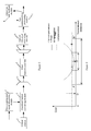
- a system that adopts the pre-compensation mode has receiving limitations, as shown in Figure 2 .
- the compensation scope is proper and the signal can be received when the transmission distance is between point A and point B; when the transmission distance does not reach point A, the signal is in the over-compensation state; when the transmission distance is beyond point B, the signal is in the under-compensation state; point C is the optimal receiving distance.
- the pre-compensating module needs to adjust the compensation amount.
- the quality of the transmit signal can be tested at the receiving end only.
- the feedback control signal must be sent from a receiving node to a sending node. This may be difficult in a complicated network, especially in a mesh network. In addition, the feedback signal may produce a delay.
- the prior art provides a tunable dispersion compensation method.
- This method is based on the combination of optical tunable dispersion compensator and receiving end electrical dispersion compensator (EDC), thus expanding the tunable dispersion compensation scope.
- the optical tunable dispersion compensator achieves a dispersion compensation scope of less than 3,000 ps/nm, and may support the transmission of a 10 Gbit/s signal on a single-mode fiber for less than 200 km.
- the EDC based on maximum likelihood sequence estimate (MLSE) may also achieve a compensation scope of less than 3,000 ps/nm.
- this compensation solution needs an additional online DCF compensation technology to implement long-distance transmission.
- the dispersion compensation method in the prior art cannot meet actual requirements with respect to long-distance dispersion compensation without online DCF and non-linear effect suppression.
- Embodiments of the present invention provide a dispersion compensation method and a fiber transmission system to overcome the weaknesses of the long-distance dispersion compensation without online DCF and to suppress the non-linear effect of the dispersion compensation in the prior art.
- Embodiments of the present invention provide the following technical solution:
- a dispersion compensation method includes:
- a fiber transmission system provided in an embodiment of the present invention includes a transmitting end, a fiber transmission line and a receiving end.
- the transmitting end includes:
- the receiving end includes:
- Allocating the dispersion compensation to both ends of the transmission line may suppress the non-linear effect
- Adjusting the amount of dispersion pre-compensation according to the network configuration information may facilitate the back-end feedback of the pre-compensation mode and improve the practicability of this technical solution;
- the system does not require an online dispersion compensating module, and a flexible dispersion compensation solution is provided for a dynamically configurable network.
- Figure 1 shows a structure of an optical transmission system that adopts the pre-compensation solution in the prior art
- Figure 2 shows a relationship between the system cost and the transmission distance of an optical transmission system that adopts the pre-compensation solution in the prior art
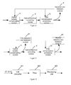
- Figure 3 shows a structure of a fiber transmission system according to an embodiment of the present invention
- Figure 4 shows a relationship between the system cost and the transmission distance of a dispersion compensation method according to an embodiment of the present invention
- Figure 5 shows a process of implementing a pre-compensation processing module according to an embodiment of the present invention
- Figure 6 shows a process of implementing a digital pre-processing module according to an embodiment of the present invention
- Figure 7 shows a module connection in a first method for post-compensation and feedback control according to an embodiment of the present invention
- Figure 8 shows a module connection in a second method for post-compensation and feedback control according to an embodiment of the present invention
- Figure 9 shows a module connection in a third method for post-compensation and feedback control according to an embodiment of the present invention.
- Figure 10 shows a structure of a detection and feedback module according to an embodiment of the present invention
- Figure 11 shows a distribution of electrical signal spectral power detected by the receiving end according to an embodiment of the present invention
- Figure 12 is a chart where the spectral power changes with the amount of dispersion according to an embodiment of the present invention.
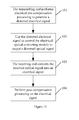
- Figure 13 is a flowchart of a dispersion compensation method according to an embodiment of the present invention.
- Figure 14 compares the emulation result of the dispersion compensation according to an embodiment of the present invention with the emulation result of the dispersion compensation in the prior art.
- Embodiments of the present invention achieve the objects of suppressing the non-linear effect and improving the system transmission performance through laying out the dispersion distribution on a transmission line reasonably, i.e., through the combination of pre-compensation and post-compensation, and by configuring the dispersion compensation of an optical network dynamically.
- a fiber transmission system provided in an embodiment of the present invention includes a transmitting end, a fiber transmission line and a receiving end.
- the transmitting end includes:
- the receiving end includes:
- the system further includes:
- an optical multiplexer 41 needs to be set between the electrical/optical converting module 3 and the fiber transmission line 5 and an optical demultiplexer 42 needs to be set between the fiber transmission line 5 and the optical/electrical converting module 6.
- the pre-compensation signal processing module 1 may adjust the optimal receiving point of the whole system through configuration. As shown in Figure 4 , the pre-compensation signal processing module 1 adjusts the optimal receiving point from point O to point O1 by adjusting the pre-compensation result. This function may adjust the dispersion compensation scope when the network configuration changes.
- An adjustable specification may be set according to the total dispersion tolerance of the system to reduce the processing complexity. If the total dispersion tolerance of the system is +/-L km, the specification is L km, [L+2L] km, ..., [L+2nL] km.
- the pre-compensation signal processing module 1 and the post-compensation processing module 7 may expand the signal receiving scope from segment AB to segment A 1 B 1 by combining pre-compensation and post-compensation.
- the pre-compensation signal processing module 1 includes:
- the network configuration information changes only when the network is rebuilt.
- a pre-encoding processing module 14 needs to be added to the pre-compensation signal processing module 1.
- the pre-encoding processing module 14 is adapted to pre-encode the transmit signal, and send the pre-encoded transmit signal to the digital pre-processing module 12.
- the digital pre-processing module 12 includes:
- the digital pre-processing module 12 may be implemented through a digital signal processor (DSP), a field programmable gate array (FPGA) or an application specific integrated circuit (ASIC).
- DSP digital signal processor
- FPGA field programmable gate array
- ASIC application specific integrated circuit
- the FPGA is used to implement the digital pre-processing module 12.
- the post-compensation processing module 7 may perform dispersion compensation in real time dynamically, and expand the dispersion tolerance scope of the system from AB to A1B1, as shown in Figure 4 .
- the post-compensation processing module 7 performs adjustment control through the following steps: by a detection module 8, detecting the quality of an electrical signal, generating an adjustment control signal, and feeding back the adjustment control signal to the post-compensation processing module 7 for adjusting the amount of dispersion compensation.
- the post-compensation processing module 7 may compensate the remaining dispersion amount of the whole system, and perform dynamic compensation by adjusting the dispersion change due to temperature change in real time.
- the post-compensation processing module 7 may be implemented through various EDCs or electronic equalizers (EEQs), for example:
- the post-compensation processing mode may compensate a small amount of dispersion only, usually within the scope of 250 km.
- the amount of dispersion that needs to be compensated at the transmitting end exceeds 75% of the total amount of dispersion of the system, as shown in Figure 14 , and the signal transmission quality is 3 dB poorer than the optimal level.
- dispersion compensation may be performed before the optical/electrical converting module receives the signal.
- the optical dispersion compensating module shown in Figure 7 is an optical fixed compensating module 70 that is untunable. A traditional DCF may be used.
- the optical dispersion compensating module in Figure 8 and Figure 9 is an optical tunable compensating module 71, for example, sampled chirped bragg grating, Gires-Tournois Etalons, loop harmonic oscillator, Mach-Zehnder interferometer (MZI), virtually imaged phased array (VIPA), waveguide grating, or a combination of grating and deformable mirror.
- MZI Mach-Zehnder interferometer
- VIPA virtually imaged phased array
- waveguide grating or a combination of grating and deformable mirror.
- a post-compensation adjustment control signal may be obtained through the feedback signal provided by the detection and feedback module 8, as shown in Figure 8 .
- a post-compensation adjustment control signal may also be obtained by detecting the quality of an optical signal before the optical signal is converted by the optical/electrical converting module, as shown in Figure 9 . That is, a first detection and feedback module 81 is set before the optical/electrical converting module. The first detection and feedback module 81 is adapted to detect the quality of an optical signal, obtain a post-compensation adjustment control signal according to the quality of the optical signal, and send the post-compensation adjustment control signal to the optical tunable compensating module 71.
- a second detection and feedback module 82 is set after a post-compensation processing module 72.
- the second detection and feedback module 82 is adapted to detect the quality of an electrical signal, obtain a post-compensation adjustment control signal according to the quality of the electrical signal, and send the post-compensation adjustment control signal to the post-compensation processing module 72.
- the detection and feedback module 8 shown in Figure 8 may detect the quality of an electrical signal through the following method:
- the first detection and feedback module 81 and the second detection and feedback module 82 shown in Figure 9 can reflect the dispersion change by detecting the change of the radio frequency signal spectral power within a specific band.
- f L is the spectral frequency of a received signal with zero power caused by dispersion. This frequency may vary with the dispersion, leading to the change of power detected within the ⁇ f spectral range, as shown in Figure 12 .
- the first detection and feedback module includes:
- the second detection and feedback module 82 includes the filter 102 and the processing unit 103 only.
- the dispersion compensation method by using the preceding system includes the following steps:
- Step 101 The transmitting end performs electrical pre-compensation processing on a digital transmit signal by using the pre-compensation signal processing module 1 to obtain a distorted electrical signal.
- the pre-encoding processing module 14 is needed to pre-encode the transmit signal.
- the pre-encoding process is as follows: inputting the transmit signal to the pre-encoding processing module 14, encoding the transmit signal to obtain a pre-encoded signal, and sending the pre-encoded signal to the digital pre-processing module 12.
- the digital pre-processing module 12 performs digital pre-processing through the following steps:
- Step 102 The distorted electrical signal is used to control the electrical/optical converting module 3 to output a distorted optical signal.
- Step 103 After the distorted optical signal is transmitted through the fiber transmission line 5, the distorted optical signal is recovered to a normal optical signal, and the recovered optical signal is sent to the receiving end.
- the receiving end converts the optical signal into an electrical signal by using the optical/electrical converting module 6, and outputs the electrical signal.
- Step 104 The post-compensating module 7 performs post-compensation processing on the electrical signal output by the receiving end.
- the post-compensating module 7 may perform real-time adjustment by detecting the post-compensation adjustment control signal output by the detection and feedback module 8.
Landscapes
- Physics & Mathematics (AREA)
- Electromagnetism (AREA)
- Engineering & Computer Science (AREA)
- Computer Networks & Wireless Communication (AREA)
- Signal Processing (AREA)
- Optical Communication System (AREA)
Applications Claiming Priority (2)
| Application Number | Priority Date | Filing Date | Title |
|---|---|---|---|
| CNA2006101677861A CN101207445A (zh) | 2006-12-21 | 2006-12-21 | 一种色散补偿方法和光纤传输系统 |
| PCT/CN2007/002587 WO2008074206A1 (en) | 2006-12-21 | 2007-08-28 | A dispersion compensation method and optical transmission system |
Publications (1)
| Publication Number | Publication Date |
|---|---|
| EP2051417A1 true EP2051417A1 (de) | 2009-04-22 |
Family
ID=39535984
Family Applications (1)
| Application Number | Title | Priority Date | Filing Date |
|---|---|---|---|
| EP07800806A Withdrawn EP2051417A1 (de) | 2006-12-21 | 2007-08-28 | Dispersionskompensationsverfahren und optisches übertragungssystem |
Country Status (4)
| Country | Link |
|---|---|
| US (1) | US20090175629A1 (de) |
| EP (1) | EP2051417A1 (de) |
| CN (2) | CN101207445A (de) |
| WO (1) | WO2008074206A1 (de) |
Cited By (3)
| Publication number | Priority date | Publication date | Assignee | Title |
|---|---|---|---|---|
| EP2438697A4 (de) * | 2010-07-14 | 2012-06-20 | Huawei Tech Co Ltd | Transponder für ein optisches kommunikationssystem und optisches kommunikationssystem |
| EP2866362A3 (de) * | 2013-10-14 | 2015-08-26 | Korea Advanced Institute of Science and Technology | Elektronische Dispersionskompensation für kostengünstigen, verteilten, rückkopplungsdirekt modulierten Laser |
| CN116318406A (zh) * | 2023-05-19 | 2023-06-23 | 深圳市飞思卓科技有限公司 | 一种用于光纤通信系统的信号补偿方法及系统 |
Families Citing this family (35)
| Publication number | Priority date | Publication date | Assignee | Title |
|---|---|---|---|---|
| US8625986B2 (en) * | 2006-09-27 | 2014-01-07 | Tti Inventions A Llc | Methods and systems for optical performance monitoring |
| JP5181770B2 (ja) * | 2008-03-27 | 2013-04-10 | 富士通株式会社 | 光伝送システム |
| CN101662326B (zh) * | 2008-08-28 | 2012-05-23 | 华为技术有限公司 | 一种光信号电均衡处理方法、装置和光纤通信系统 |
| EP2395683A4 (de) * | 2009-02-04 | 2015-01-28 | Nec Corp | Optisches kommunikationssystem und optisches kommunikationsverfahren |
| CN101895346B (zh) * | 2009-05-18 | 2013-11-06 | 财团法人工业技术研究院 | Oofdm系统的传送器及其预补偿光纤色散所引起的延迟的方法 |
| JP2011055088A (ja) * | 2009-08-31 | 2011-03-17 | Fujitsu Ltd | 光伝送システム、光伝送装置及び波長分散補償方法 |
| JP5375519B2 (ja) * | 2009-10-26 | 2013-12-25 | 富士通株式会社 | 非線形歪検出回路、光受信機、光伝送システム、および非線形歪検出方法 |
| JP5644446B2 (ja) * | 2010-12-06 | 2014-12-24 | 富士通株式会社 | 光伝送装置 |
| JP5760419B2 (ja) | 2010-12-13 | 2015-08-12 | 富士通株式会社 | 光送信装置および光送信方法 |
| CN102511136B (zh) | 2011-02-17 | 2015-04-15 | 华为技术有限公司 | 色散评估器和评估色散的方法 |
| JP5747629B2 (ja) * | 2011-04-18 | 2015-07-15 | 富士通株式会社 | 光伝送装置および光スイッチ装置 |
| CN102347797A (zh) * | 2011-11-02 | 2012-02-08 | 华中科技大学 | 一种多功能的光信号处理系统 |
| JP5861516B2 (ja) * | 2012-03-16 | 2016-02-16 | 富士通株式会社 | 光伝送装置及び特性補償方法 |
| JPWO2014155775A1 (ja) * | 2013-03-27 | 2017-02-16 | 日本電気株式会社 | 信号処理装置、光通信システム、及び信号処理方法 |
| CN104683031A (zh) * | 2013-11-29 | 2015-06-03 | 中兴通讯股份有限公司 | 一种消除非线性效应的方法、发射机及接收机 |
| US9673911B2 (en) * | 2014-05-13 | 2017-06-06 | Infinera Corporation | Tracking nonlinear cross-phase modulation noise and linewidth induced jitter in coherent optical fiber communication links |
| US9571198B2 (en) | 2014-07-25 | 2017-02-14 | Futurewei Technologies, Inc. | Compensation of non-linear transmitter impairments in optical communication networks |
| US9590730B2 (en) | 2014-10-01 | 2017-03-07 | Futurewei Technologies, Inc. | Optical transmitter with optical receiver-specific dispersion pre-compensation |
| EP3342068A1 (de) * | 2015-08-24 | 2018-07-04 | Telefonaktiebolaget LM Ericsson (PUBL) | Steuerung eines optischen senders in einem funk-über-faser-system |
| US9680574B1 (en) * | 2015-11-30 | 2017-06-13 | Futurewei Technologies, Inc. | Frequency domain optical channel estimation |
| US10225022B2 (en) * | 2016-06-02 | 2019-03-05 | Tektronix, Inc. | Electro-optic sensor system |
| JP6376211B2 (ja) * | 2016-11-30 | 2018-08-22 | Nttエレクトロニクス株式会社 | 波長分散補償装置、波長分散補償方法及び通信装置 |
| CN111224718B (zh) * | 2018-11-23 | 2023-06-20 | 阿里巴巴集团控股有限公司 | 光模块以及光模块信号处理方法 |
| BR102018076057A2 (pt) * | 2018-12-14 | 2020-06-23 | Fundacao Cpqd - Centro De Pesquisa E Desenvolvimento Em Telecomunicacoes | Método para compensação de dispersão cromática em sinais digitais de banda limitada |
| CN111436012B (zh) * | 2019-01-15 | 2022-08-12 | 阿里巴巴集团控股有限公司 | 信号处理系统、交换机以及光模块 |
| CN112671465A (zh) * | 2020-11-24 | 2021-04-16 | 深圳市宇虹飞科技有限公司 | 一种光通信系统噪声的补偿方法及系统 |
| CN114553314B (zh) * | 2020-11-27 | 2023-08-22 | 华为技术有限公司 | 非线性损伤补偿方法、装置、传输设备以及存储介质 |
| CN114696908A (zh) * | 2020-12-28 | 2022-07-01 | 华为技术有限公司 | 一种色散补偿装置、发射机、接收机和色散补偿方法 |
| CN115733557B (zh) * | 2022-10-17 | 2025-04-29 | 北京航空航天大学 | 一种光信号传输损伤的自适应数字域补偿系统及补偿方法 |
| CN115955278B (zh) * | 2023-03-15 | 2023-06-23 | 天津艾洛克通讯设备科技有限公司 | 一种基于光纤信号分析的数字面板 |
| JP2024145438A (ja) * | 2023-03-31 | 2024-10-15 | 富士通株式会社 | 光受信機及び光受信方法 |
| CN116193057B (zh) * | 2023-04-26 | 2023-07-07 | 广东视腾电子科技有限公司 | 一种多端口传输的光纤视频延长方法及系统 |
| CN117394918A (zh) * | 2023-12-12 | 2024-01-12 | 湖南省康普通信技术有限责任公司 | 一种基于光模块实现信号处理的方法及光模块 |
| CN118337284B (zh) * | 2024-05-14 | 2025-02-14 | 湘潭大学 | 基于原生光载波的复数信号场恢复系统及恢复方法 |
| CN118944759B (zh) * | 2024-07-16 | 2025-09-05 | 华中科技大学 | 一种无中继传输系统及提升无中继光通信传输距离的方法 |
Family Cites Families (13)
| Publication number | Priority date | Publication date | Assignee | Title |
|---|---|---|---|---|
| US5430568A (en) * | 1992-12-01 | 1995-07-04 | Scientific-Atlanta, Inc. | Optical communications system for transmitting information signals having different wavelengths over a same optical fiber |
| US6574389B1 (en) * | 1999-05-24 | 2003-06-03 | Broadband Royalty | Optical communication with pre-compensation for odd order distortion in modulation and transmission |
| US6330381B1 (en) * | 2000-06-30 | 2001-12-11 | Nortel Networks Limited | Methods, systems, media and signals for determining optimum pre-compensation and optimization of an optical system |
| US7224911B2 (en) * | 2001-06-07 | 2007-05-29 | Jds Uniphase Corporation | Adaptive distortion compensation in optical fiber communication networks |
| US7058311B1 (en) * | 2002-03-15 | 2006-06-06 | Xtera Communications, Inc. | System and method for dispersion compensation in an optical communication system |
| US7379670B2 (en) * | 2002-03-21 | 2008-05-27 | Tyco Telecommunications (Us) Inc. | Method and apparatus for chromatic dispersion compensation |
| US7382984B2 (en) * | 2002-10-03 | 2008-06-03 | Nortel Networks Limited | Electrical domain compensation of optical dispersion in an optical communications system |
| JP4468656B2 (ja) * | 2003-05-27 | 2010-05-26 | 株式会社日立製作所 | 信号波形劣化補償器 |
| US7522847B2 (en) * | 2003-12-19 | 2009-04-21 | Broadcom Corporation | Continuous time filter-decision feedback equalizer architecture for optical channel equalization |
| US7805082B1 (en) * | 2004-09-21 | 2010-09-28 | Ciena Corporation | Optical laser control for optical communications systems |
| US20060067699A1 (en) * | 2004-09-24 | 2006-03-30 | Sethumadhavan Chandrasekhar | Equalizer having tunable optical and electronic dispersion compensation |
| EP1802006B1 (de) * | 2005-12-20 | 2010-06-02 | Alcatel Lucent | Vorrichtung und Verfahren zur automatischen Abstimmung einer Farbzerstreuungskompensation für WDM Übertragungssysteme unter Verwendung einer verteilten Raman Co-Pumpe |
| EP1855399B1 (de) * | 2006-05-08 | 2009-08-26 | Alcatel Lucent | Verfahren zum Betreiben und Optimieren eines WDM-Übertragungssystems und entsprechendes Computerprogrammprodukt |
-
2006
- 2006-12-21 CN CNA2006101677861A patent/CN101207445A/zh active Pending
-
2007
- 2007-08-28 WO PCT/CN2007/002587 patent/WO2008074206A1/zh not_active Ceased
- 2007-08-28 CN CNA2007800003972A patent/CN101317352A/zh active Pending
- 2007-08-28 EP EP07800806A patent/EP2051417A1/de not_active Withdrawn
-
2009
- 2009-03-13 US US12/403,865 patent/US20090175629A1/en not_active Abandoned
Non-Patent Citations (1)
| Title |
|---|
| See references of WO2008074206A1 * |
Cited By (4)
| Publication number | Priority date | Publication date | Assignee | Title |
|---|---|---|---|---|
| EP2438697A4 (de) * | 2010-07-14 | 2012-06-20 | Huawei Tech Co Ltd | Transponder für ein optisches kommunikationssystem und optisches kommunikationssystem |
| EP2866362A3 (de) * | 2013-10-14 | 2015-08-26 | Korea Advanced Institute of Science and Technology | Elektronische Dispersionskompensation für kostengünstigen, verteilten, rückkopplungsdirekt modulierten Laser |
| CN116318406A (zh) * | 2023-05-19 | 2023-06-23 | 深圳市飞思卓科技有限公司 | 一种用于光纤通信系统的信号补偿方法及系统 |
| CN116318406B (zh) * | 2023-05-19 | 2023-08-08 | 深圳市飞思卓科技有限公司 | 一种用于光纤通信系统的信号补偿方法及系统 |
Also Published As
| Publication number | Publication date |
|---|---|
| WO2008074206A1 (en) | 2008-06-26 |
| US20090175629A1 (en) | 2009-07-09 |
| CN101207445A (zh) | 2008-06-25 |
| CN101317352A (zh) | 2008-12-03 |
Similar Documents
| Publication | Publication Date | Title |
|---|---|---|
| EP2051417A1 (de) | Dispersionskompensationsverfahren und optisches übertragungssystem | |
| CN112771792B (zh) | 针对在50gbps和更大值的pamn光收发器中使用的模拟电子光纤色散和带宽预补偿(edpc)的装置和方法 | |
| Sun et al. | Transmission of 28-Gb/s duobinary and PAM-4 signals using DML for optical access network | |
| US8041226B2 (en) | Optical transceiver with equalizing function and a method to setup the optical transceiver | |
| Eiselt et al. | Experimental Demonstration of 112-Gbit/s PAM-4 over up to 80 km SSMF at 1550 nm for Inter-DCI Applications | |
| Kaneda et al. | Nonlinear equalizer for 112-Gb/s SSB-PAM4 in 80-km dispersion uncompensated link | |
| US20090202248A1 (en) | Wavelength division multiplexing system, method and device for its residual dispersion compensation | |
| US20080063396A1 (en) | Optical Subchannels From a Single Lightwave Source | |
| US7542685B2 (en) | System and method for automatic chromatic dispersion compensation | |
| Li et al. | 4× 28 Gb/s PAM4 long-reach PON using low complexity nonlinear compensation | |
| Zhang et al. | Symmetrical 50-Gb/s/λ PAM-4 TDM-PON at O-band supporting 26 dB+ loss budget using low-bandwidth optics and semiconductor optical amplifier | |
| US6829549B2 (en) | Implementation of a post detection chromatic dispersion compensation transfer function | |
| US11539441B1 (en) | Chirp-compensating transmitter and method | |
| Xia et al. | Comparison of NRZ and duo-binary format in adaptive equalization assisted 10G-optics based 25G-EPON | |
| Lowery | Optical ofdm | |
| CN103999381B (zh) | 预均衡光发送机以及预均衡光发送方法 | |
| US20020167703A1 (en) | Tandem filters for reducing intersymbol interference in optical communications systems | |
| Lu et al. | Investigation of pre-equalization technique for pluggable CFP2-ACO transceivers in beyond 100 Gb/s transmissions | |
| Figueiredo et al. | Investigation of 56-GBd PAM4 bandwidth and chromatic dispersion limitations for data center applications | |
| Hossain et al. | Feasibility of Transmitting 270 Gbit/s with PAM-8 in O-band CWDM4 with IM/DD System | |
| US11736199B1 (en) | Systems and methods for phase compensation | |
| Wang et al. | Demonstration of 4× 100 Gbit/s PAM-4 transmission over 40 km in an IM/DD system based on narrow band DMLs | |
| Yu et al. | 42.8 Gbit/s chirp-managed signal transmission over 20 km standard SMF at 1550 nm without DCF | |
| Zynal et al. | Improving Communication Performance Through Fiber Amplifier EDFA | |
| Sun et al. | Transmission of 28-Gb/s duobinary signals over 45-km SSMF Using 1.55-µm directly modulated laser |
Legal Events
| Date | Code | Title | Description |
|---|---|---|---|
| PUAI | Public reference made under article 153(3) epc to a published international application that has entered the european phase |
Free format text: ORIGINAL CODE: 0009012 |
|
| 17P | Request for examination filed |
Effective date: 20090306 |
|
| AK | Designated contracting states |
Kind code of ref document: A1 Designated state(s): AT BE BG CH CY CZ DE DK EE ES FI FR GB GR HU IE IS IT LI LT LU LV MC MT NL PL PT RO SE SI SK TR |
|
| AX | Request for extension of the european patent |
Extension state: AL BA HR MK RS |
|
| 17Q | First examination report despatched |
Effective date: 20090921 |
|
| STAA | Information on the status of an ep patent application or granted ep patent |
Free format text: STATUS: THE APPLICATION IS DEEMED TO BE WITHDRAWN |
|
| 18D | Application deemed to be withdrawn |
Effective date: 20110224 |