EP2052247B1 - Verfahren und vorrichtung zum akustischen testen von holzpfählen - Google Patents
Verfahren und vorrichtung zum akustischen testen von holzpfählen Download PDFInfo
- Publication number
- EP2052247B1 EP2052247B1 EP07766470A EP07766470A EP2052247B1 EP 2052247 B1 EP2052247 B1 EP 2052247B1 EP 07766470 A EP07766470 A EP 07766470A EP 07766470 A EP07766470 A EP 07766470A EP 2052247 B1 EP2052247 B1 EP 2052247B1
- Authority
- EP
- European Patent Office
- Prior art keywords
- transducer
- peaks
- pole
- acoustic signal
- spectral profile
- Prior art date
- Legal status (The legal status is an assumption and is not a legal conclusion. Google has not performed a legal analysis and makes no representation as to the accuracy of the status listed.)
- Not-in-force
Links
- 238000000034 method Methods 0.000 title claims description 21
- 238000012360 testing method Methods 0.000 title claims description 18
- 230000003595 spectral effect Effects 0.000 claims abstract description 20
- 238000010998 test method Methods 0.000 claims abstract description 3
- 238000002347 injection Methods 0.000 claims 1
- 239000007924 injection Substances 0.000 claims 1
- 239000002023 wood Substances 0.000 description 10
- 238000001228 spectrum Methods 0.000 description 9
- 230000006870 function Effects 0.000 description 6
- 230000001747 exhibiting effect Effects 0.000 description 4
- 238000004891 communication Methods 0.000 description 3
- 235000008331 Pinus X rigitaeda Nutrition 0.000 description 2
- 235000011613 Pinus brutia Nutrition 0.000 description 2
- 241000018646 Pinus brutia Species 0.000 description 2
- 230000009194 climbing Effects 0.000 description 2
- 238000001514 detection method Methods 0.000 description 2
- 230000001965 increasing effect Effects 0.000 description 2
- 238000012423 maintenance Methods 0.000 description 2
- 238000005259 measurement Methods 0.000 description 2
- 230000004044 response Effects 0.000 description 2
- 241000238631 Hexapoda Species 0.000 description 1
- 238000010521 absorption reaction Methods 0.000 description 1
- 230000015572 biosynthetic process Effects 0.000 description 1
- 230000015556 catabolic process Effects 0.000 description 1
- 238000006243 chemical reaction Methods 0.000 description 1
- 238000010168 coupling process Methods 0.000 description 1
- 238000005859 coupling reaction Methods 0.000 description 1
- 238000013016 damping Methods 0.000 description 1
- 238000006731 degradation reaction Methods 0.000 description 1
- 230000001066 destructive effect Effects 0.000 description 1
- 238000010586 diagram Methods 0.000 description 1
- 230000004069 differentiation Effects 0.000 description 1
- 230000005284 excitation Effects 0.000 description 1
- 238000011065 in-situ storage Methods 0.000 description 1
- 230000001939 inductive effect Effects 0.000 description 1
- 230000000977 initiatory effect Effects 0.000 description 1
- 238000009434 installation Methods 0.000 description 1
- 238000005065 mining Methods 0.000 description 1
- 238000012544 monitoring process Methods 0.000 description 1
- 239000003755 preservative agent Substances 0.000 description 1
- 230000002335 preservative effect Effects 0.000 description 1
- 230000000644 propagated effect Effects 0.000 description 1
- 230000005236 sound signal Effects 0.000 description 1
- 238000003860 storage Methods 0.000 description 1
- 239000000126 substance Substances 0.000 description 1
- 238000012549 training Methods 0.000 description 1
Images



Classifications
-
- G—PHYSICS
- G01—MEASURING; TESTING
- G01N—INVESTIGATING OR ANALYSING MATERIALS BY DETERMINING THEIR CHEMICAL OR PHYSICAL PROPERTIES
- G01N29/00—Investigating or analysing materials by the use of ultrasonic, sonic or infrasonic waves; Visualisation of the interior of objects by transmitting ultrasonic or sonic waves through the object
- G01N29/04—Analysing solids
- G01N29/11—Analysing solids by measuring attenuation of acoustic waves
-
- G—PHYSICS
- G01—MEASURING; TESTING
- G01B—MEASURING LENGTH, THICKNESS OR SIMILAR LINEAR DIMENSIONS; MEASURING ANGLES; MEASURING AREAS; MEASURING IRREGULARITIES OF SURFACES OR CONTOURS
- G01B17/00—Measuring arrangements characterised by the use of infrasonic, sonic or ultrasonic vibrations
-
- G—PHYSICS
- G01—MEASURING; TESTING
- G01N—INVESTIGATING OR ANALYSING MATERIALS BY DETERMINING THEIR CHEMICAL OR PHYSICAL PROPERTIES
- G01N29/00—Investigating or analysing materials by the use of ultrasonic, sonic or infrasonic waves; Visualisation of the interior of objects by transmitting ultrasonic or sonic waves through the object
- G01N29/04—Analysing solids
- G01N29/12—Analysing solids by measuring frequency or resonance of acoustic waves
-
- G—PHYSICS
- G01—MEASURING; TESTING
- G01N—INVESTIGATING OR ANALYSING MATERIALS BY DETERMINING THEIR CHEMICAL OR PHYSICAL PROPERTIES
- G01N29/00—Investigating or analysing materials by the use of ultrasonic, sonic or infrasonic waves; Visualisation of the interior of objects by transmitting ultrasonic or sonic waves through the object
- G01N29/22—Details, e.g. general constructional or apparatus details
- G01N29/24—Probes
- G01N29/2412—Probes using the magnetostrictive properties of the material to be examined, e.g. electromagnetic acoustic transducers [EMAT]
-
- G—PHYSICS
- G01—MEASURING; TESTING
- G01N—INVESTIGATING OR ANALYSING MATERIALS BY DETERMINING THEIR CHEMICAL OR PHYSICAL PROPERTIES
- G01N29/00—Investigating or analysing materials by the use of ultrasonic, sonic or infrasonic waves; Visualisation of the interior of objects by transmitting ultrasonic or sonic waves through the object
- G01N29/44—Processing the detected response signal, e.g. electronic circuits specially adapted therefor
- G01N29/4409—Processing the detected response signal, e.g. electronic circuits specially adapted therefor by comparison
- G01N29/4427—Processing the detected response signal, e.g. electronic circuits specially adapted therefor by comparison with stored values, e.g. threshold values
-
- G—PHYSICS
- G01—MEASURING; TESTING
- G01N—INVESTIGATING OR ANALYSING MATERIALS BY DETERMINING THEIR CHEMICAL OR PHYSICAL PROPERTIES
- G01N29/00—Investigating or analysing materials by the use of ultrasonic, sonic or infrasonic waves; Visualisation of the interior of objects by transmitting ultrasonic or sonic waves through the object
- G01N29/44—Processing the detected response signal, e.g. electronic circuits specially adapted therefor
- G01N29/46—Processing the detected response signal, e.g. electronic circuits specially adapted therefor by spectral analysis, e.g. Fourier analysis or wavelet analysis
-
- G—PHYSICS
- G01—MEASURING; TESTING
- G01N—INVESTIGATING OR ANALYSING MATERIALS BY DETERMINING THEIR CHEMICAL OR PHYSICAL PROPERTIES
- G01N33/00—Investigating or analysing materials by specific methods not covered by groups G01N1/00 - G01N31/00
- G01N33/46—Wood
-
- G—PHYSICS
- G01—MEASURING; TESTING
- G01N—INVESTIGATING OR ANALYSING MATERIALS BY DETERMINING THEIR CHEMICAL OR PHYSICAL PROPERTIES
- G01N2291/00—Indexing codes associated with group G01N29/00
- G01N2291/02—Indexing codes associated with the analysed material
- G01N2291/024—Mixtures
- G01N2291/02466—Biological material, e.g. blood
-
- G—PHYSICS
- G01—MEASURING; TESTING
- G01N—INVESTIGATING OR ANALYSING MATERIALS BY DETERMINING THEIR CHEMICAL OR PHYSICAL PROPERTIES
- G01N2291/00—Indexing codes associated with group G01N29/00
- G01N2291/04—Wave modes and trajectories
- G01N2291/042—Wave modes
- G01N2291/0421—Longitudinal waves
-
- G—PHYSICS
- G01—MEASURING; TESTING
- G01N—INVESTIGATING OR ANALYSING MATERIALS BY DETERMINING THEIR CHEMICAL OR PHYSICAL PROPERTIES
- G01N2291/00—Indexing codes associated with group G01N29/00
- G01N2291/04—Wave modes and trajectories
- G01N2291/042—Wave modes
- G01N2291/0422—Shear waves, transverse waves, horizontally polarised waves
-
- G—PHYSICS
- G01—MEASURING; TESTING
- G01N—INVESTIGATING OR ANALYSING MATERIALS BY DETERMINING THEIR CHEMICAL OR PHYSICAL PROPERTIES
- G01N2291/00—Indexing codes associated with group G01N29/00
- G01N2291/04—Wave modes and trajectories
- G01N2291/048—Transmission, i.e. analysed material between transmitter and receiver
-
- G—PHYSICS
- G01—MEASURING; TESTING
- G01N—INVESTIGATING OR ANALYSING MATERIALS BY DETERMINING THEIR CHEMICAL OR PHYSICAL PROPERTIES
- G01N2291/00—Indexing codes associated with group G01N29/00
- G01N2291/10—Number of transducers
- G01N2291/102—Number of transducers one emitter, one receiver
Definitions
- This invention relates to a method of and an apparatus for testing wooden poles and other wooden structural elements, for example to detect degradation due to rot.
- Utility poles are typically a length of the trunk of a pine tree. After cutting, the poles are seasoned for sufficient time to dry and stabilise the timber, and are then treated with preservative chemicals. The poles are intended to have a pre-determined length buried in the ground, to provide sufficient structural stability. In some conditions, such poles can remain serviceable for many years - some have remained sound for several decades.
- rot can occur, substantially reducing the safe working life of the pole.
- a ladder to be leant against the pole to support the person doing the work.
- the simplest form of testing has been carried out by striking the pole with a hammer and listening to the resultant sound. With careful training, a person can distinguish by listening to this resultant sound between a sound pole and one which has been weakened by decay.
- the pole is deemed unsafe for ladder access, the work may need to be carried out from an access hoist, which involves extra cost and possible delay, but it may become necessary for the pole to be replaced, which is even more costly. It is therefore important to ensure that testing is as accurate as possible, and accuracy is difficult to achieve where the test criteria are subjective.
- WO02/08749 discloses an apparatus and a method for testing wood, comprising injecting an input acoustic signal into the element, detecting a return acoustic signal at a surface of the element, determining a spectral profile for the return signal, detecting in at least a predetermined range in the spectral profile each resonance peak whose amplitude exceeds a first predetermined value and determining a characteristic of the wood.
- US-A-4 399 701 discloses a system involving the generation of a continuous longitudinal acoustic wave by inserting transducers (for example piezoelectric transducers) into slots cut into the pole at locations spaced apart along its length.
- the input acoustic frequency is varied over a range that includes, say the first twenty standing wave harmonic frequencies of the pole. If the output contains harmonic resonances, then this can be taken as an indication of a sound pole, while a pole containing rot is said to yield resonant frequencies which are not in harmonic relationship with one another. It is not explained how the judgment on these issues is made.
- a major disadvantage of this technique is that it necessitates the cutting of slots into the pole, something that utilities operators would consider highly undesirable, since it would tend to weaken the pole and to provide a possible future route into the interior of the pole of damaging moisture and attacking organisms. It is therefore desirable to provide a testing method which is non-invasive and which provides a more accurate indication of the state of the wood in the pole.
- a method of testing an elongate wooden element comprising injecting an input acoustic signal into the element, detecting a return acoustic signal at a surface of the element, deter-mining a spectral profile for the return signal, detecting in at least a predetermined range in the spectral profile each resonance peak whose amplitude exceeds a first predetermined value, determining from the resonance peaks so detected the number of higher peaks whose amplitude exceeds 3 dB, calculating for each of said higher peaks a quality factor Q, determining a mean quality value Q m , and comparing Q m with a predetermined value to provide an indication of the presence or absence of external decay of the element, calculating a ratio R of the number of higher peaks to the number of resonance peaks detected, calculating the statistical spread S of the average Q for the spectral profile, and comparing the values of R and S with a predetermined boundary function F n (R,S) to determine acceptability or
- the critical values for a, b and r are suitably assigned on the basis of multiple observations on poles (for example) known to have no decay and poles known to have internal and/or external decay.
- the wooden element may be a utility pole, and the pole may have one end portion thereof buried in the ground in conventional manner.
- the method of the invention may also be applicable to other wooden elements, such as structural timbers in situ, for example piles, rafters and joists or timber frame elements.
- the invention also provides apparatus for testing an elongate wooden element, comprising an acoustic transmit transducer attachable temporarily and non-invasively to an external side surface of the element, a signal generator for applying an acoustic signal to the acoustic signal to the transmit transducer at an amplitude sufficient to couple acoustic energy into the element, a controller connected to the signal generator for controlling the frequency of the acoustic signal, and a receive transducer attachable to an external surface of the element and connected to the controller, the controller being programmed to:
- the transmit transducer may be a magnetostrictive transducer, since this type of transducer is capable of generating a high power and is of low compliance.
- the receive transducer may for example be an accelerometer, but may also be a magnetostrictive transducer. In one embodiment of the invention, the transmit and receive transducers are the same single transducer.
- the high power sound waves generated by the transducer can couple sufficient of the transversely-applied energy into all modes to resonate the structure. This is due to diffraction and/or mode-coupling. Diffraction occurs due to the finite size of the radiating face of the transducer, and mode conversion works due to the anisotropy of sound speed in wood.
- the technique is especially effective below ground, effectively measuring the increased loss of energy from (a) a decay pocket leaking energy into the ground due to the reduced acoustic impedance mismatch between the pole and the ground (if the impedances of the decayed wood and the ground were the same, all the sound would escape and there would be no resonance) and/or (b) the soft spongy nature of the decayed wood increasing inherent acoustic absorption.
- the method of the invention is totally non-destructive - the transmit transducer is temporarily attached to the side of the wooden element (e.g. the pole), for example by a strap passing around the pole, and does not require the formation of any apertures in the wood which might lead to the entry of decay organisms or wood-attacking insects.
- the method and apparatus of the invention determine whether the length of a wooden element, for example a utility pole, differs from the specified length. Since the length of a utility pole is known prior to installation, it can be used to determine the predicted resonant frequencies of the element that subsequent measurements can confirm. It will be appreciated that the pole length can only be gauged with certainty if the longitudinal velocity of sound in the pole is known. Then the frequencies of the transverse mode resonances can be predicted, and the observed frequencies compared with them.
- the controller may be linked to or include storage means to store data relating to each test, for example to be downloaded subsequently to a central data base.
- This local data may be stored in internal non-volatile memory and/or on a removable memory card. This will allow central collection of data and preventative maintenance programmes to be developed as the database grows.
- the apparatus may incorporate a Global Positioning System (GPS) receiver to enable the time and position of the tests to be accurately recorded.
- GPS Global Positioning System
- a utility pole 1 has one end thereof 1 a buried in the ground. If decay occurs in the buried end 1 a, the pole may become inadequately supported and could fail when abnormally loaded, for example by a maintenance engineer climbing a ladder placed against it.
- the test apparatus consists of a transmit transducer 2 in the form of a magnetostrictive actuator which is temporarily clamped against the surface of the pole, for example at the 3 metre mark relative to the lowermost end, by means of a removable strap, for example.
- the driving signal for the transducer 2 is supplied by a waveform generator 3 by way of an amplifier 4.
- the waveform generator is controlled by a microcontroller 5.
- the output from the transducer 6 passes to a tracking receiver 7 by way of an amplifier 8.
- the tracking receiver 7 is also controlled by the microcontroller 5.
- the signal received by the tracking receiver passes through an amplifier 9 and an analogue to digital converter 10 whose output is connected to the microcontroller 5.
- a keyboard and display 11 are connected to the microcontroller to enable the operator to control the apparatus.
- the serial or other interface 12 is provided for communication between the microcontroller and a host computer 13 to permit downloading of data to the host computer.
- a GPS module 14 provides accurate time and position data to the microcontroller 5.
- the microcontroller is programmed to sweep the frequency of the audio signal applied to the transmit transducer 2 in 1000 steps on a logarithmic scale across a frequency decade which encompasses the fundamental resonant frequency of the element and/or at least one harmonic thereof, typically from about 100Hz to about 1000Hz.
- the signal received by the receive transducer 6 is sampled by the converter 10 for each step, and the resultant frequency and voltage samples are processed by the microprocessor to detect the number N of all discernable peaks in the spectral range arising from the acoustic response of the pole. It might be appropriate to define this as encompassing all peaks having an amplitude greater than a predetermined value, which might be set at 0.5dB or 1dB, for example.
- the microprocessor then detects a number n of higher peaks out of this total having an amplitude greater than 3dB. For each of the peaks whose amplitude exceeds 3dB a quality factor Q is calculated in accordance with well-known procedures. An average Q, Q m , is then calculated for a predetermined spectral range, typically 200Hz to 1000Hz. The microprocessor compares this with a predetermined value to give an indication that external decay is present when Q m is less than the predetermined value. In the assessment of pine poles carrying communications wires, for example, a Q m figure below 14 has been found to be indicative of the presence of external decay.
- the microprocessor calculates the ratio R of the number of higher peaks n to the total number of peaks N. This factor (a) gauges the number of significant resonance peaks in the spectral range and distinguishes these from smaller spurious peaks attributable, for example, to noise, and (b) assesses the break-up of a spectrum that is identified with the occurrence of internal decay.
- the microprocessor is programmed to calculate the standard deviation about the mean Q m . This is also a factor that enables the detection, and gauges the extent, of internal decay in the wood.
- Typical critical values for each parameter that are employed in the sort process are shown in the flow diagram illustrated in Figure 3 .
- Q m is a single valued independent parameter, R and S are not. Their interdependence is expressed as a function F n (R,S), chosen to generate multiple pairs of values (R, S) that enable the discrimination between spectra characteristic of 'good' poles and those containing decay.
- a single transmit/receive magnetostrictive transducer 20 is used, temporarily clamped to the post at the 3 metre mark.
- An echo cancellation module 21 is connected between the transducer 20 and the input and output amplifiers 4 and 8. It will be recognised by those skilled in the art that fast digital signal processors can be programmed to perform echo cancellation.
- the remainder of the apparatus is as described with reference to Figure 1 , and the same reference numerals are used in the Figure.
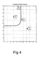
- Figure 4 illustrates a plot of R against S values for four different test poles A, B, C and D.
- a boundary function is illustrated by the line F in the graph.
- r is a constant that regulates the curvature of the boundary.
- the critical values for a, b and r are assigned on the basis of multiple observations on poles (for example) known to have no decay and poles known to have internal and/or external decay.
- test poles A, B, C and D illustrate respectively a pole with both internal and external decay, a pole with external decay only, a pole with internal decay only, and a sound pole without significant decay. It will be seen from Figure 4 that poles B and D fall within the boundary demarcating acceptable poles, while A and C fall outside and are therefore deemed unacceptable. For example, they might be scheduled for replacement, and until replacement a ban might be imposed on climbing the poles or placing ladders against them.
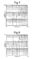
- Figures 5 to 8 are graphs illustrating the frequency spectrum obtained for each of poles A, B, C and D.
- Figure 5 illustrates the spectrum for a pole having both internal and external decay. It will be seen that the peaks are generally broad, leading to a lower Q factor, indicating external decay, but with approximately half the peaks exceeding 3dB, leading to a reasonable R value. The statistical spread of peaks S is, however, higher than for the acceptable level, placing the test outside the acceptable region, and indicating the presence of internal decay as well as external decay.
- Figure 6 exhibits distinct, but broad peaks, yielding a Q m of about 7, which indicates the presence of external decay.
- the high proportion of peaks above 3dB gives a high R value.
- the statistical spread S is 44%. These indicate the absence of internal decay and place the pole within the region of acceptability for internal decay, but the external decay indicated by the low Q value renders this pole unacceptable.
- Figure 7 has a number of good distinct peaks yielding a Q m of about 19, which indicates an absence of external decay. However, there are many lower peaks, yielding a low R value. The statistical spread S is also low, these factors together indicating the presence of internal decay and placing the pole in the unacceptable region.
- Figure 8 illustrates the spectrum of a sound pole.
- the spectrum shows a good number of sharp resonance peaks, yielding a Q m of about 18, and R value of 69 and an S value of 30, placing the pole firmly in the acceptable region.
Landscapes
- Physics & Mathematics (AREA)
- Life Sciences & Earth Sciences (AREA)
- Health & Medical Sciences (AREA)
- Chemical & Material Sciences (AREA)
- General Physics & Mathematics (AREA)
- General Health & Medical Sciences (AREA)
- Immunology (AREA)
- Pathology (AREA)
- Analytical Chemistry (AREA)
- Biochemistry (AREA)
- Engineering & Computer Science (AREA)
- Signal Processing (AREA)
- Mathematical Physics (AREA)
- Spectroscopy & Molecular Physics (AREA)
- Acoustics & Sound (AREA)
- Wood Science & Technology (AREA)
- Food Science & Technology (AREA)
- Medicinal Chemistry (AREA)
- Electromagnetism (AREA)
- Investigating Or Analyzing Materials By The Use Of Ultrasonic Waves (AREA)
- Investigating Strength Of Materials By Application Of Mechanical Stress (AREA)
Claims (15)
- Verfahren zum Testen eines länglichen Holzelements, umfassend Einbringen eines akustischen Eingangssignals in das Element, Erfassen eines akustischen Antwortsignals an einer Oberfläche des Elements, Bestimmen eines Spektralprofils für das Antwortsignal, Erfassen in zumindest einem vorgegebenen Bereich des Spektralprofils eines jeden Resonanzpeaks, dessen Amplitude einen ersten vorgegebenen Wert übersteigt, Bestimmen anhand der so erfassten Resonanzpeaks die Anzahl von höheren Peaks, deren Amplitude 3dB übersteigt, Berechnen eines Qualitätsfaktors Q für jeden der höheren Peaks, Bestimmen eines mittleren Qualitätswerts Qm und Vergleichen von Qm mit einem vorgegebenen Wert, um eine Aussage über das Vorhandensein oder Fehlen äußerer Verrottung des Elements zu erhalten, Berechnen eines Verhältnisses R aus der Anzahl von höheren Peaks zu der Anzahl der erfassten Resonanzpeaks, Berechnen der statistischen Streuung S des Durchschnitts Q des Spektralprofils, und Vergleichen der Werte von R und S mit einer vorgegebenen Randfunktion Fn(R, S), um die Akzeptanz oder Inakzeptanz des länglichen Holzelements zu bestimmen.
- Verfahren nach Anspruch 1, bei dem die Randfunktion wie folgt vorgegeben ist


wobei die Konstante a den Wert von S innerhalb des Limits von R = 100% und die Konstante b den Wert von R innerhalb des Limits von S = 0% repräsentiert, und r eine Konstante ist, welche die Krümmung des Rands einstellt. - Verfahren nach Anspruch 1 oder 2, umfassend ein Einbringen des akustischen Eingangssignals unter Verwendung eines magnetostriktiven Wandlers.
- Verfahren nach Anspruch 1, 2 oder 3, umfassend ein Erfassen des akustischen Antwortsignals unter Verwendung eines magnetostriktiven Wandlers.
- Verfahren nach Anspruch 1, 2 oder 3, umfassend ein Einbringen des akustischen Eingangssignals unter Verwendung eines Sendewandlers, der konfiguriert ist, um zusätzlich als ein Empfangswandler zu arbeiten.
- Verfahren nach einem der vorgenannten Ansprüche, umfassend ein Variieren der Frequenz des akustischen Eingangssignals während der Einspeisung desselben.
- Verfahren nach Anspruch 6, bei dem die Frequenz über einen vorgegebenen Bereich von Frequenzen streicht.
- Verfahren nach Anspruch 7, bei dem der Bereich 100 Hz bis 1000 Hz ist.
- Vorrichtung zum Testen eines länglichen Holzelements, umfassend einen Sendewandler, der temporär und nicht-invasiv an einer außenseitigen Oberfläche des Elements befestigbar ist, einen Signalgenerator zum Anlegen eines akustischen Signals an den Sendewandler mit einer Amplitude, die ausreichend ist, um akustische Energie in das Element einzukoppeln, eine Steuereinrichtung, die mit dem Signalgenerator verbunden ist, um die Frequenz des akustischen Signals einzustellen, und einen Empfangswandler, der an einer äußeren Oberfläche des Elements befestigbar ist und mit der Steuereinrichtung verbunden ist, wobei die Steuereinrichtung programmiert ist, um:in zumindest einem vorgegebenen Bereich des Spektralprofils jeden Resonanzpeak zu erfassen, dessen Amplitude einen ersten vorgegebenen Wert übersteigt;anhand der so erfassten Resonanzpeaks die Anzahl von höheren Peaks zu bestimmen, deren Amplitude 3dB übersteigt;einen Qualitätsfaktor Q für jeden der höheren Peaks zu berechnen, einen mittleren Qualitätswert Qm zu berechnen und Qm mit einem vorgegebenen Wert zu vergleichen, um eine Aussage über das Vorhandensein oder das Fehlen äußerer Verrottung des Elements zu erhalten;ein Verhältnis R aus der Anzahl von höheren Peaks zu der Anzahl der erfassten Resonanzpeaks zu berechnen;die statistische Streuung S des Durchschnitts Q des Spektralprofils zu berechnen; unddie Werte von R und S mit einer vorgegebenen Randfunktion Fn(R, S) zu vergleichen, um die Akzeptanz oder Inakzeptanz des länglichen Holzelements zu bestimmen.
- Vorrichtung nach Anspruch 9, bei dem der Sendewandler ein magnetostriktiver Wandler ist.
- Vorrichtung nach Anspruch 9 oder 10, bei dem der Empfangswandler ein magnetostriktiver Wandler ist.
- Vorrichtung nach Anspruch 9 oder 10, bei dem der Sendewandler konfiguriert ist, um zusätzlich als Empfangswandler zu arbeiten.
- Vorrichtung nach einem der Ansprüche 9 bis 12, bei dem die Steuereinrichtung programmiert ist, um die Frequenz des dem Sendewandler zugeführten Signals innerhalb eines Frequenzbereichs zu variieren.
- Vorrichtung nach Anspruch 13, bei dem die Steuerfrequenz über den Frequenzbereich streicht.
- Vorrichtung nach Anspruch 14, bei dem der Bereich 100 Hz bis 1000 Hz ist.
Applications Claiming Priority (2)
| Application Number | Priority Date | Filing Date | Title |
|---|---|---|---|
| GB0615151A GB2440555A (en) | 2006-07-31 | 2006-07-31 | Acoustic testing of wooden elements |
| PCT/GB2007/050458 WO2008015477A1 (en) | 2006-07-31 | 2007-07-30 | Method and apparatus for acoustically testing wooden poles |
Publications (2)
| Publication Number | Publication Date |
|---|---|
| EP2052247A1 EP2052247A1 (de) | 2009-04-29 |
| EP2052247B1 true EP2052247B1 (de) | 2012-01-25 |
Family
ID=37006456
Family Applications (1)
| Application Number | Title | Priority Date | Filing Date |
|---|---|---|---|
| EP07766470A Not-in-force EP2052247B1 (de) | 2006-07-31 | 2007-07-30 | Verfahren und vorrichtung zum akustischen testen von holzpfählen |
Country Status (6)
| Country | Link |
|---|---|
| US (1) | US7971485B2 (de) |
| EP (1) | EP2052247B1 (de) |
| AT (1) | ATE543094T1 (de) |
| AU (1) | AU2007280188A1 (de) |
| GB (1) | GB2440555A (de) |
| WO (1) | WO2008015477A1 (de) |
Families Citing this family (23)
| Publication number | Priority date | Publication date | Assignee | Title |
|---|---|---|---|---|
| SE510763C2 (sv) * | 1996-12-20 | 1999-06-21 | Sandvik Ab | Ämne för ett borr eller en pinnfräs för metallbearbetning |
| NZ536400A (en) * | 2004-11-04 | 2007-05-31 | Fibre Gen Instr Ltd | Timber harvesting apparatus |
| US20120134239A1 (en) * | 2010-11-28 | 2012-05-31 | Struthers Sheldon L | Micro sonic transmitter |
| US9310340B2 (en) | 2012-05-23 | 2016-04-12 | International Electronic Machines Corp. | Resonant signal analysis-based inspection of rail components |
| US9389205B2 (en) | 2012-05-23 | 2016-07-12 | International Electronic Machines Corp. | Resonant signal analysis-based inspection of rail components |
| US9267925B2 (en) * | 2012-09-07 | 2016-02-23 | Polexpert, Llc | Pole integrity meter and method of determining pole integrity |
| CA2890124C (en) * | 2012-11-01 | 2021-06-15 | Sp Sveriges Tekniska Forskningsinstitut Ab | Method and system for automatic determination of timber quality in frozen or unfrozen condition |
| US10033470B2 (en) | 2013-08-29 | 2018-07-24 | Battelle Memorial Institute | Acoustic transmission devices and process for making and using same |
| US10033469B2 (en) | 2013-08-29 | 2018-07-24 | Battelle Memorial Institute | Injectable acoustic transmission devices and process for making and using same |
| US20150355144A1 (en) * | 2014-06-09 | 2015-12-10 | Polexpert Llc | Systems and Methods for Measuring and Managing Site Inspection Profile Data |
| WO2016120774A1 (en) * | 2015-01-27 | 2016-08-04 | Oxys Solutions S.R.L. | Method and device for the structural control of wooden poles |
| US10101429B2 (en) * | 2015-02-25 | 2018-10-16 | Battelle Memorial Institute | Acoustic transmission device and process for tracking selected hosts |
| US10067112B2 (en) | 2015-09-30 | 2018-09-04 | Battelle Memorial Institute | Autonomous sensor fish to support advanced hydropower development |
| WO2017077486A1 (en) * | 2015-11-06 | 2017-05-11 | Peter Lee | System and method for assessment of irregularity in a wooden material surrounded by a substrate |
| US11278004B2 (en) | 2015-12-15 | 2022-03-22 | Battelle Memorial Institute | Transmitters for animals and methods for transmitting from animals |
| US10236920B2 (en) | 2015-12-15 | 2019-03-19 | Battelle Memorial Institute | Signal transmitter and methods for transmitting signals from animals |
| US10531639B2 (en) | 2016-08-25 | 2020-01-14 | Battelle Memorial Institute | Systems and methods for monitoring organisms within an aquatic environment |
| GB201809227D0 (en) | 2018-06-05 | 2018-07-25 | Univ Cape Town | A sensor and a sensor network for monitoring utility poles |
| US11533818B2 (en) | 2019-03-12 | 2022-12-20 | Battelle Memorial Institute | Sensor assemblies and methods for emulating interaction of entities within water systems |
| US11079358B2 (en) | 2019-04-25 | 2021-08-03 | Saudi Arabian Oil Company | Remotely assessing real-time wooden pole integrity |
| US11162869B2 (en) | 2019-09-30 | 2021-11-02 | King Fahd University Of Petroleum And Minerals | Double force two sensor vibration method |
| US11175263B2 (en) | 2020-02-24 | 2021-11-16 | King Fahd University Of Petroleum And Minerals | Apparatus and method for generating, measuring, and evaluating vibrational modes in cylindrical objects |
| FR3120444B1 (fr) * | 2021-03-03 | 2025-10-24 | Commissariat A L’Energie Atomique Et Aux Energies Alternatives | Procédé de détection de fissures dans une pièce en alliage d’aluminium réalisée par fabrication additive. |
Family Cites Families (8)
| Publication number | Priority date | Publication date | Assignee | Title |
|---|---|---|---|---|
| AU502728B2 (en) * | 1975-06-05 | 1979-08-09 | Fanner Pty. Ltd. | Testing wooden poles |
| US4301684A (en) * | 1980-01-31 | 1981-11-24 | Rockwell International Corporation | Ultrasonic non-destructive evaluation technique for structures of complex geometry |
| US4399701A (en) * | 1980-06-03 | 1983-08-23 | Unisearch Limited | Method and means for detecting decay in wood |
| US5804728A (en) * | 1994-09-07 | 1998-09-08 | The Regents Of The University Of California | Method and apparatus for non-intrusively detecting hidden defects caused by bio-deterioration in living trees and round wood materials |
| US6276209B1 (en) * | 1999-09-30 | 2001-08-21 | Perceptron, Inc. | System and method of assessing the structural properties of wooden members using ultrasound |
| US6367330B1 (en) * | 2000-03-10 | 2002-04-09 | Perceptron, Inc. | Defect parameter for wooden members |
| NZ505896A (en) * | 2000-07-21 | 2003-05-30 | Ind Res Ltd | Method and apparatus for assessing or predicting characteristics of wood or other materials by varying frequency of acoustic transmitter and sensing a response |
| US6829938B2 (en) * | 2002-10-04 | 2004-12-14 | The Johns Hopkins University | Method and apparatus for selecting trees for harvest |
-
2006
- 2006-07-31 GB GB0615151A patent/GB2440555A/en not_active Withdrawn
-
2007
- 2007-07-30 US US12/309,826 patent/US7971485B2/en not_active Expired - Fee Related
- 2007-07-30 AU AU2007280188A patent/AU2007280188A1/en not_active Abandoned
- 2007-07-30 WO PCT/GB2007/050458 patent/WO2008015477A1/en not_active Ceased
- 2007-07-30 EP EP07766470A patent/EP2052247B1/de not_active Not-in-force
- 2007-07-30 AT AT07766470T patent/ATE543094T1/de active
Also Published As
| Publication number | Publication date |
|---|---|
| US20090188320A1 (en) | 2009-07-30 |
| AU2007280188A1 (en) | 2008-02-07 |
| WO2008015477A1 (en) | 2008-02-07 |
| ATE543094T1 (de) | 2012-02-15 |
| GB0615151D0 (en) | 2006-09-06 |
| GB2440555A (en) | 2008-02-06 |
| EP2052247A1 (de) | 2009-04-29 |
| US7971485B2 (en) | 2011-07-05 |
Similar Documents
| Publication | Publication Date | Title |
|---|---|---|
| EP2052247B1 (de) | Verfahren und vorrichtung zum akustischen testen von holzpfählen | |
| US5804728A (en) | Method and apparatus for non-intrusively detecting hidden defects caused by bio-deterioration in living trees and round wood materials | |
| AU779834B2 (en) | Log testing apparatus | |
| US5621172A (en) | Method and apparatus for testing material strengths | |
| US7146846B2 (en) | Non-destructive testing of in-service wooden beams | |
| US6889551B2 (en) | Method of estimating timber stiffness profiles | |
| AU2001252798A1 (en) | A method of estimating timber stiffness profiles | |
| US6769306B2 (en) | Log cutting procedures | |
| AU2006200562B2 (en) | Method and apparatus for assessing or predicting the characteristics of wood | |
| CA2360778C (en) | Log cutting procedures | |
| US20130340892A1 (en) | Method of estimating timber stiffness profiles | |
| US11175263B2 (en) | Apparatus and method for generating, measuring, and evaluating vibrational modes in cylindrical objects | |
| NZ337015A (en) | Measuring density of logs by striking log end and analysing resultant echos | |
| AU2004226981A1 (en) | Log Testing Apparatus | |
| Lawday et al. | A non-invasive method for evaluating trees | |
| Mohamady et al. | Analysis of uncertainties of TPA with tonal excitation | |
| CN120162511A (zh) | 一种隧道衬砌隐形剥落剥离埋深快速计算方法及系统 | |
| CA2484456A1 (en) | Non-destructive testing of in-service wooden beams | |
| Craighead et al. | Assessment of structural integrity of wooden poles | |
| RU2542622C1 (ru) | Способ и устройство для измерения толщины и плотности гололедных отложений | |
| Shen et al. | Acoustic emission detection of damage in reinforced concrete conduit | |
| NZ515734A (en) | Log analysis using an impactor and accelerometer | |
| AU2004222710A1 (en) | Non-destructive testing of in-service wooden beams | |
| NZ610108A (en) | A method of estimating timber stiffness profiles |
Legal Events
| Date | Code | Title | Description |
|---|---|---|---|
| PUAI | Public reference made under article 153(3) epc to a published international application that has entered the european phase |
Free format text: ORIGINAL CODE: 0009012 |
|
| 17P | Request for examination filed |
Effective date: 20090227 |
|
| AK | Designated contracting states |
Kind code of ref document: A1 Designated state(s): AT BE BG CH CY CZ DE DK EE ES FI FR GB GR HU IE IS IT LI LT LU LV MC MT NL PL PT RO SE SI SK TR |
|
| AX | Request for extension of the european patent |
Extension state: AL BA HR MK RS |
|
| GRAJ | Information related to disapproval of communication of intention to grant by the applicant or resumption of examination proceedings by the epo deleted |
Free format text: ORIGINAL CODE: EPIDOSDIGR1 |
|
| GRAP | Despatch of communication of intention to grant a patent |
Free format text: ORIGINAL CODE: EPIDOSNIGR1 |
|
| DAX | Request for extension of the european patent (deleted) | ||
| RAP1 | Party data changed (applicant data changed or rights of an application transferred) |
Owner name: CPI QUETRA LIMITED |
|
| GRAS | Grant fee paid |
Free format text: ORIGINAL CODE: EPIDOSNIGR3 |
|
| GRAA | (expected) grant |
Free format text: ORIGINAL CODE: 0009210 |
|
| AK | Designated contracting states |
Kind code of ref document: B1 Designated state(s): AT BE BG CH CY CZ DE DK EE ES FI FR GB GR HU IE IS IT LI LT LU LV MC MT NL PL PT RO SE SI SK TR |
|
| REG | Reference to a national code |
Ref country code: GB Ref legal event code: FG4D |
|
| REG | Reference to a national code |
Ref country code: CH Ref legal event code: EP |
|
| REG | Reference to a national code |
Ref country code: AT Ref legal event code: REF Ref document number: 543094 Country of ref document: AT Kind code of ref document: T Effective date: 20120215 |
|
| REG | Reference to a national code |
Ref country code: IE Ref legal event code: FG4D |
|
| REG | Reference to a national code |
Ref country code: DE Ref legal event code: R096 Ref document number: 602007020280 Country of ref document: DE Effective date: 20120322 |
|
| REG | Reference to a national code |
Ref country code: NL Ref legal event code: VDEP Effective date: 20120125 |
|
| LTIE | Lt: invalidation of european patent or patent extension |
Effective date: 20120125 |
|
| PG25 | Lapsed in a contracting state [announced via postgrant information from national office to epo] |
Ref country code: NL Free format text: LAPSE BECAUSE OF FAILURE TO SUBMIT A TRANSLATION OF THE DESCRIPTION OR TO PAY THE FEE WITHIN THE PRESCRIBED TIME-LIMIT Effective date: 20120125 Ref country code: BE Free format text: LAPSE BECAUSE OF FAILURE TO SUBMIT A TRANSLATION OF THE DESCRIPTION OR TO PAY THE FEE WITHIN THE PRESCRIBED TIME-LIMIT Effective date: 20120125 Ref country code: IS Free format text: LAPSE BECAUSE OF FAILURE TO SUBMIT A TRANSLATION OF THE DESCRIPTION OR TO PAY THE FEE WITHIN THE PRESCRIBED TIME-LIMIT Effective date: 20120525 Ref country code: LT Free format text: LAPSE BECAUSE OF FAILURE TO SUBMIT A TRANSLATION OF THE DESCRIPTION OR TO PAY THE FEE WITHIN THE PRESCRIBED TIME-LIMIT Effective date: 20120125 Ref country code: BG Free format text: LAPSE BECAUSE OF FAILURE TO SUBMIT A TRANSLATION OF THE DESCRIPTION OR TO PAY THE FEE WITHIN THE PRESCRIBED TIME-LIMIT Effective date: 20120425 |
|
| PG25 | Lapsed in a contracting state [announced via postgrant information from national office to epo] |
Ref country code: LV Free format text: LAPSE BECAUSE OF FAILURE TO SUBMIT A TRANSLATION OF THE DESCRIPTION OR TO PAY THE FEE WITHIN THE PRESCRIBED TIME-LIMIT Effective date: 20120125 Ref country code: GR Free format text: LAPSE BECAUSE OF FAILURE TO SUBMIT A TRANSLATION OF THE DESCRIPTION OR TO PAY THE FEE WITHIN THE PRESCRIBED TIME-LIMIT Effective date: 20120426 Ref country code: PL Free format text: LAPSE BECAUSE OF FAILURE TO SUBMIT A TRANSLATION OF THE DESCRIPTION OR TO PAY THE FEE WITHIN THE PRESCRIBED TIME-LIMIT Effective date: 20120125 Ref country code: PT Free format text: LAPSE BECAUSE OF FAILURE TO SUBMIT A TRANSLATION OF THE DESCRIPTION OR TO PAY THE FEE WITHIN THE PRESCRIBED TIME-LIMIT Effective date: 20120525 Ref country code: FI Free format text: LAPSE BECAUSE OF FAILURE TO SUBMIT A TRANSLATION OF THE DESCRIPTION OR TO PAY THE FEE WITHIN THE PRESCRIBED TIME-LIMIT Effective date: 20120125 |
|
| PGFP | Annual fee paid to national office [announced via postgrant information from national office to epo] |
Ref country code: FR Payment date: 20120706 Year of fee payment: 6 |
|
| REG | Reference to a national code |
Ref country code: AT Ref legal event code: MK05 Ref document number: 543094 Country of ref document: AT Kind code of ref document: T Effective date: 20120125 |
|
| PG25 | Lapsed in a contracting state [announced via postgrant information from national office to epo] |
Ref country code: CY Free format text: LAPSE BECAUSE OF FAILURE TO SUBMIT A TRANSLATION OF THE DESCRIPTION OR TO PAY THE FEE WITHIN THE PRESCRIBED TIME-LIMIT Effective date: 20120125 |
|
| PG25 | Lapsed in a contracting state [announced via postgrant information from national office to epo] |
Ref country code: EE Free format text: LAPSE BECAUSE OF FAILURE TO SUBMIT A TRANSLATION OF THE DESCRIPTION OR TO PAY THE FEE WITHIN THE PRESCRIBED TIME-LIMIT Effective date: 20120125 Ref country code: DK Free format text: LAPSE BECAUSE OF FAILURE TO SUBMIT A TRANSLATION OF THE DESCRIPTION OR TO PAY THE FEE WITHIN THE PRESCRIBED TIME-LIMIT Effective date: 20120125 Ref country code: CZ Free format text: LAPSE BECAUSE OF FAILURE TO SUBMIT A TRANSLATION OF THE DESCRIPTION OR TO PAY THE FEE WITHIN THE PRESCRIBED TIME-LIMIT Effective date: 20120125 Ref country code: SE Free format text: LAPSE BECAUSE OF FAILURE TO SUBMIT A TRANSLATION OF THE DESCRIPTION OR TO PAY THE FEE WITHIN THE PRESCRIBED TIME-LIMIT Effective date: 20120125 Ref country code: RO Free format text: LAPSE BECAUSE OF FAILURE TO SUBMIT A TRANSLATION OF THE DESCRIPTION OR TO PAY THE FEE WITHIN THE PRESCRIBED TIME-LIMIT Effective date: 20120125 Ref country code: SI Free format text: LAPSE BECAUSE OF FAILURE TO SUBMIT A TRANSLATION OF THE DESCRIPTION OR TO PAY THE FEE WITHIN THE PRESCRIBED TIME-LIMIT Effective date: 20120125 |
|
| PGFP | Annual fee paid to national office [announced via postgrant information from national office to epo] |
Ref country code: IE Payment date: 20120705 Year of fee payment: 6 Ref country code: GB Payment date: 20120704 Year of fee payment: 6 |
|
| PG25 | Lapsed in a contracting state [announced via postgrant information from national office to epo] |
Ref country code: SK Free format text: LAPSE BECAUSE OF FAILURE TO SUBMIT A TRANSLATION OF THE DESCRIPTION OR TO PAY THE FEE WITHIN THE PRESCRIBED TIME-LIMIT Effective date: 20120125 |
|
| PLBE | No opposition filed within time limit |
Free format text: ORIGINAL CODE: 0009261 |
|
| STAA | Information on the status of an ep patent application or granted ep patent |
Free format text: STATUS: NO OPPOSITION FILED WITHIN TIME LIMIT |
|
| PGFP | Annual fee paid to national office [announced via postgrant information from national office to epo] |
Ref country code: IT Payment date: 20120726 Year of fee payment: 6 Ref country code: DE Payment date: 20120731 Year of fee payment: 6 |
|
| 26N | No opposition filed |
Effective date: 20121026 |
|
| PG25 | Lapsed in a contracting state [announced via postgrant information from national office to epo] |
Ref country code: AT Free format text: LAPSE BECAUSE OF FAILURE TO SUBMIT A TRANSLATION OF THE DESCRIPTION OR TO PAY THE FEE WITHIN THE PRESCRIBED TIME-LIMIT Effective date: 20120125 |
|
| REG | Reference to a national code |
Ref country code: DE Ref legal event code: R097 Ref document number: 602007020280 Country of ref document: DE Effective date: 20121026 |
|
| PG25 | Lapsed in a contracting state [announced via postgrant information from national office to epo] |
Ref country code: MC Free format text: LAPSE BECAUSE OF NON-PAYMENT OF DUE FEES Effective date: 20120731 |
|
| REG | Reference to a national code |
Ref country code: CH Ref legal event code: PL |
|
| PG25 | Lapsed in a contracting state [announced via postgrant information from national office to epo] |
Ref country code: LI Free format text: LAPSE BECAUSE OF NON-PAYMENT OF DUE FEES Effective date: 20120731 Ref country code: CH Free format text: LAPSE BECAUSE OF NON-PAYMENT OF DUE FEES Effective date: 20120731 |
|
| PG25 | Lapsed in a contracting state [announced via postgrant information from national office to epo] |
Ref country code: MT Free format text: LAPSE BECAUSE OF FAILURE TO SUBMIT A TRANSLATION OF THE DESCRIPTION OR TO PAY THE FEE WITHIN THE PRESCRIBED TIME-LIMIT Effective date: 20120125 |
|
| PG25 | Lapsed in a contracting state [announced via postgrant information from national office to epo] |
Ref country code: ES Free format text: LAPSE BECAUSE OF FAILURE TO SUBMIT A TRANSLATION OF THE DESCRIPTION OR TO PAY THE FEE WITHIN THE PRESCRIBED TIME-LIMIT Effective date: 20120506 |
|
| GBPC | Gb: european patent ceased through non-payment of renewal fee |
Effective date: 20130730 |
|
| REG | Reference to a national code |
Ref country code: IE Ref legal event code: MM4A |
|
| REG | Reference to a national code |
Ref country code: DE Ref legal event code: R119 Ref document number: 602007020280 Country of ref document: DE Effective date: 20140201 |
|
| REG | Reference to a national code |
Ref country code: FR Ref legal event code: ST Effective date: 20140331 |
|
| PG25 | Lapsed in a contracting state [announced via postgrant information from national office to epo] |
Ref country code: GB Free format text: LAPSE BECAUSE OF NON-PAYMENT OF DUE FEES Effective date: 20130730 Ref country code: DE Free format text: LAPSE BECAUSE OF NON-PAYMENT OF DUE FEES Effective date: 20140201 Ref country code: TR Free format text: LAPSE BECAUSE OF FAILURE TO SUBMIT A TRANSLATION OF THE DESCRIPTION OR TO PAY THE FEE WITHIN THE PRESCRIBED TIME-LIMIT Effective date: 20120125 |
|
| PG25 | Lapsed in a contracting state [announced via postgrant information from national office to epo] |
Ref country code: FR Free format text: LAPSE BECAUSE OF NON-PAYMENT OF DUE FEES Effective date: 20130731 Ref country code: IT Free format text: LAPSE BECAUSE OF NON-PAYMENT OF DUE FEES Effective date: 20130730 Ref country code: LU Free format text: LAPSE BECAUSE OF NON-PAYMENT OF DUE FEES Effective date: 20120730 |
|
| PG25 | Lapsed in a contracting state [announced via postgrant information from national office to epo] |
Ref country code: HU Free format text: LAPSE BECAUSE OF FAILURE TO SUBMIT A TRANSLATION OF THE DESCRIPTION OR TO PAY THE FEE WITHIN THE PRESCRIBED TIME-LIMIT Effective date: 20070730 Ref country code: IE Free format text: LAPSE BECAUSE OF NON-PAYMENT OF DUE FEES Effective date: 20130730 |