EP2052436B1 - Antenne multiaxiale et procédé d'utilisation dans les outils d'extraction - Google Patents
Antenne multiaxiale et procédé d'utilisation dans les outils d'extraction Download PDFInfo
- Publication number
- EP2052436B1 EP2052436B1 EP06803663.1A EP06803663A EP2052436B1 EP 2052436 B1 EP2052436 B1 EP 2052436B1 EP 06803663 A EP06803663 A EP 06803663A EP 2052436 B1 EP2052436 B1 EP 2052436B1
- Authority
- EP
- European Patent Office
- Prior art keywords
- coil
- bobbin
- coils
- generate
- magnetic field
- Prior art date
- Legal status (The legal status is an assumption and is not a legal conclusion. Google has not performed a legal analysis and makes no representation as to the accuracy of the status listed.)
- Expired - Fee Related
Links
Images



Classifications
-
- G—PHYSICS
- G01—MEASURING; TESTING
- G01V—GEOPHYSICS; GRAVITATIONAL MEASUREMENTS; DETECTING MASSES OR OBJECTS; TAGS
- G01V3/00—Electric or magnetic prospecting or detecting; Measuring magnetic field characteristics of the earth, e.g. declination, deviation
- G01V3/08—Electric or magnetic prospecting or detecting; Measuring magnetic field characteristics of the earth, e.g. declination, deviation operating with magnetic or electric fields produced or modified by objects or geological structures or by detecting devices
- G01V3/10—Electric or magnetic prospecting or detecting; Measuring magnetic field characteristics of the earth, e.g. declination, deviation operating with magnetic or electric fields produced or modified by objects or geological structures or by detecting devices using induction coils
- G01V3/104—Electric or magnetic prospecting or detecting; Measuring magnetic field characteristics of the earth, e.g. declination, deviation operating with magnetic or electric fields produced or modified by objects or geological structures or by detecting devices using induction coils using several coupled or uncoupled coils
-
- G—PHYSICS
- G01—MEASURING; TESTING
- G01V—GEOPHYSICS; GRAVITATIONAL MEASUREMENTS; DETECTING MASSES OR OBJECTS; TAGS
- G01V3/00—Electric or magnetic prospecting or detecting; Measuring magnetic field characteristics of the earth, e.g. declination, deviation
- G01V3/18—Electric or magnetic prospecting or detecting; Measuring magnetic field characteristics of the earth, e.g. declination, deviation specially adapted for well-logging
-
- H—ELECTRICITY
- H01—ELECTRIC ELEMENTS
- H01Q—ANTENNAS, i.e. RADIO AERIALS
- H01Q1/00—Details of, or arrangements associated with, antennas
- H01Q1/04—Adaptation for subterranean or subaqueous use
-
- H—ELECTRICITY
- H01—ELECTRIC ELEMENTS
- H01Q—ANTENNAS, i.e. RADIO AERIALS
- H01Q25/00—Antennas or antenna systems providing at least two radiating patterns
-
- H—ELECTRICITY
- H01—ELECTRIC ELEMENTS
- H01Q—ANTENNAS, i.e. RADIO AERIALS
- H01Q3/00—Arrangements for changing or varying the orientation or the shape of the directional pattern of the waves radiated from an antenna or antenna system
- H01Q3/26—Arrangements for changing or varying the orientation or the shape of the directional pattern of the waves radiated from an antenna or antenna system varying the relative phase or relative amplitude of energisation between two or more active radiating elements; varying the distribution of energy across a radiating aperture
-
- H—ELECTRICITY
- H01—ELECTRIC ELEMENTS
- H01Q—ANTENNAS, i.e. RADIO AERIALS
- H01Q7/00—Loop antennas with a substantially uniform current distribution around the loop and having a directional radiation pattern in a plane perpendicular to the plane of the loop
-
- H—ELECTRICITY
- H01—ELECTRIC ELEMENTS
- H01F—MAGNETS; INDUCTANCES; TRANSFORMERS; SELECTION OF MATERIALS FOR THEIR MAGNETIC PROPERTIES
- H01F5/00—Coils
- H01F5/02—Coils wound on non-magnetic supports, e.g. formers
- H01F2005/027—Coils wound on non-magnetic supports, e.g. formers wound on formers for receiving several coils with perpendicular winding axes, e.g. for antennae or inductive power transfer
Definitions
- the present invention relate to antenna systems and electromagnetic sensors. Some embodiments relate to the measurement of subsurface formations. Some embodiments relate to measurement while drilling (MWD) operations.
- MWD measurement while drilling
- Electromagnetic sensors are often used in downhole operations, including while drilling, to measure the physical properties of subsurface formations. Many of these electromagnetic sensors use one or more coils to generate magnetic fields. These sensors, for example, include so-called induction, propagation, and nuclear-magnetic resonance (NMR) tools, which may use one or more coils that operate as antennas to generate and/or receive magnetic fields. Often, in order to achieve the desired performance, these tools carry groups of coils with their magnetic vectors oriented in different directions.
- NMR nuclear-magnetic resonance
- these conventional tools carry groups of coils with their magnetic vectors oriented in different directions.
- One problem with these conventional tools is that their bodies are often made from conductive material (e.g., metal), which makes it difficult for the coils to be positioned to perform in an optimal fashion.
- Another problem with these conventional tools is that the coils are different sizes requiring a separate calibration for the size and position of each coil. This makes it difficult to accurately tune and calibrate the coil system as a whole.
- a method for constructing co-located antennas includes winding a first antenna on a support, the first antenna having a first magnetic dipole in a first orientation; and winding a second antenna on the support through a first set of openings in the support, the second antenna having a second magnetic dipole in a second orientation, wherein the first orientation is different from the second orientation, and wherein a center of the first magnetic dipole substantially co-locates with a center of the second magnetic dipole.
- GB 2,387,033 A discloses an antenna for an electromagnetic well logging tool that comprises a core having a conductor arranged on its outer surface in a pattern such that the antenna has a magnetic dipole moment perpendicular to the longitudinal axis of the core.
- FIG. 1 illustrates a multi-axial antenna system in accordance with some embodiments of the present invention.
- Multi-axial antenna system 100 comprises at least three co-located coils wound around toroidal-shaped bobbin 102. Each coil may generate a magnetic field in a mutually orthogonal direction.
- Multi-axial antenna system 100 comprises first coil 104 wound around a portion of bobbin 102 through central recess 112 of bobbin 102 to generate a magnetic field in substantially first direction 134 when current flows through first coil 104.
- Multi-axial antenna system 100 also comprises second coil 106 wound around a second portion of bobbin 102 through central recess 112 to generate a magnetic field in substantially second direction 136 when current flows through second coil 106.
- Second direction 136 is orthogonal to first direction 134.
- Multi-axial antenna system 100 also comprises third coil 108 wound longitudinally around bobbin 102 to generate a magnetic field in substantially third direction 138 when current flows through third coil 108.
- Third direction 138 is orthogonal to first direction 134 and second direction 136.
- any mutual inductance between coils 104, 106 & 108 may be significantly reduced and may even approach zero due to the orthogonal positioning of each of coils 104, 106 & 108, although the scope of the invention is not limited in this respect.
- first direction 134 may be the x-direction
- second direction 136 may be the y-direction
- third direction 138 may be the z-direction as shown, although the scope of the invention is not limited in this respect.
- first coil 104 and second coil 106 may comprise sets of frame-shaped turns and third coil 108 may comprise a solenoid.
- multi-axial antenna system 100 may be used to transmit magnetic fields in different directions, while in other embodiments, multi-axial antenna system 100 may be used to receive magnetic fields from the different directions.
- one or more multi-axial antenna systems similar to multi-axial antenna system 100 may be used for transmitting magnetic fields and one or more other multi-axial antenna systems similar to multi-axial antenna system 100 may be used to sense return magnetic fields that are generated by the transmitting antenna(s), although the scope of the invention is not limited in this respect.
- multi-axial antenna system 100 may be used for both the transmission and reception of magnetic fields, although the scope of the invention is not limited in this respect.
- antenna system 100 may be suitable for use as an electromagnetic sensor.
- antenna system 100 may be utilized as part of a logging tool, such as a multi-component induction tool, a propagation tool, or a nuclear magnetic resonance (NMR) sensor, although the scope of the invention is not limited in this respect.
- antenna system 100 may be utilized during Measurement-While-Drilling (MWD) operations, Logging-While-Drilling (LWD) operations, or wireline operations, although the scope of the invention is not limited in these respects.
- MWD Measurement-While-Drilling
- LWD Logging-While-Drilling
- wireline operations although the scope of the invention is not limited in these respects.
- central recess 112 may be substantially circular to receive tool body 120 of a downhole tool.
- Tool body 120 may comprise metal or other conductive material.
- First and second directions 134 & 136 may be orthogonal to a tool axis which may run parallel to third direction 138. In these embodiments, first and second directions 134 & 136 maybe transverse with respect to the axis of bobbin 102.
- first coil 104 may be positioned on bobbin 102 at approximately ninety-degrees with respect to second coil 106, and first and second coils 104 & 106 may be spaced apart by central angle 105 on bobbin 102 as illustrated.
- Third coil 108 may be wound longitudinally around bobbin 102 to provide three co-located antennas.
- third coil 108 may be wound first on bobbin 102, and coils 104 & 106 may be wound secondly around coil 108, although the scope of the invention is not limited in this respect.
- bobbin 102 may be keyed to prevent antenna system 100 from rotating or sliding with respect to tool body 120, although the scope of the invention is not limited in this respect.
- bobbin 102 may carry first and second coils 104 & 106, while a separate external bobbin may carry third coil 108, although the scope of the invention is not limited in this respect.
- the axial position of the two bobbins may be adjusted and fixed independently to provide independent tuning for the coils on each bobbin.
- first and second coils 104 & 106 are the same size, separate tuning coils 104 & 106 may not be required.
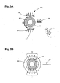
- FIG. 2A is a functional view of a first coil and a tool body.
- FIG. 2B illustrates a cross-sectional view of a first coil, a bobbin and a tool body.
- first coil 104 may comprise first and second sections 114 & 124.
- First and second sections 114 & 124 may be wound and connected in such a way that current flowing through sections 114 & 124 generate combined magnetic field 144 substantially in direction 134.
- First and second sections 114 & 124 may be wound in opposite directions to generate combined magnetic field 144 substantially in direction 134.
- First and second sections 114 & 124 may be wound in the same direction and current may be provided in opposite directions to generate combined magnetic field 144 substantially in direction 134.
- Coil 104 is formed by a plurality of loops, which may generate a magnetic moment that is substantially normal to the plane of the loops (i.e., in direction 134 of magnetic field 144). For clarity, bobbin 102 is not illustrated in FIG. 2A .
- FIG. 2C is a functional view of a second coil and a tool body.
- FIG. 2D illustrates a cross-sectional view of a second coil, a bobbin and a tool body.
- second coil 106 may comprise third and fourth sections 116 & 126.
- Third and fourth sections 116 & 126 may be wound and connected in such a way that current flowing through sections 116 & 126 generate combined magnetic field 146 substantially in direction 136.
- Third and fourth sections 116 & 126 may be wound in opposite directions to generate combined magnetic field 146 substantially in direction 136.
- Third and fourth sections 116 & 126 may be wound in the same direction and current may be provided in opposite directions to generate combined magnetic field 146 substantially in direction 136.
- Coil 106 is formed by a plurality of loops, which may generate a magnetic moment that is substantially normal to the plane of the loops (i.e., in direction 136 of magnetic field 146). For clarity, bobbin 102 is not illustrated in FIG. 2C .
- multi-axial antenna system 100 may also comprise first thru-wires 154 to electrically couple the first and second sections 114 & 124 of first coil 104.
- Multi-axial antenna system may also include second thru-wires 156 to electrically couple third and fourth sections 116 & 126 of second coil 106.
- First thru-wires 154 may be twisted to form a twisted pair minimizing external magnetic fields.
- Second thru-wires 156 may also be twisted to form a twisted pair minimizing external magnetic fields. The twisted pairs may be run through grooves in bobbin 102, discussed in more detail below.
- First thru-wires 154 may couple first and second sections 114 & 124 in series, and second thru-wires 156 may couple third and fourth sections 116 & 126 in series.
- first thru-wires 154 couple first and second sections 114 & 124 in parallel, and second thru-wires 156 couple third and fourth sections 116 & 126 in parallel, although other combinations are also suitable.
- first and second coils 104 & 106 may be substantially identical in size and shape and may be co-located in substantially the same longitudal position (i.e., with respect to tool body 120), although the scope of the invention is not limited in this respect.
- the origins of the magnetic moments of first and second coils 104 & 106 may be in the same position making the tuning and the calibration of first and second coils 104 & 106 simpler and quicker to accomplish.
- bobbin 102 comprises an electrically non-conductive and/or insulating material.
- bobbin 102 may comprise a ceramic material, fiberglass, a thermoplastic such as poly-ether-ether-ketone (PEEK), as well as other plastics, although other non-conductive materials may also be suitable.
- PEEK poly-ether-ether-ketone
- antenna system 100 may be protected by a housing or sleeve (not illustrated) that may be substantially transparent to radio-frequency signals.
- the housing or sleeve may comprise fiberglass or a thermoplastic although other materials may also be suitable.
- coils 104, 106 & 108 of antenna, system 100 may be potted in a non-conductive material, such as rubber or epoxy inside the housing or sleeve, although the scope of the invention is not limited in this respect.
- the housing or sleeve may be pressure balanced to compensate for pressure in a borehole, although the scope of the invention is not limited in this respect.
- bobbin 102 may have a high-permeability ( ⁇ r ) core such as ferrite, although the scope of the invention is not limited in this respect.
- the permeability of the core may range from one to up to several thousands. Unlike conventional toroidal coils, due to the direction of the windings and/or the current through coils 104 & 106, little or no magnetic flux circulates within the core.
- the phase and/or amplitude of currents provided to first, second and third coils 104, 106 & 108 maybe varied to generate magnetic fields, respectively, in the first, second and third directions 134, 136 & 138.
- antenna system 100 may be able to simulate a fixed tilted-coil antenna system used in downhole operations, although the scope of the invention is not limited in this respect.
- each coil 104, 106 & 108 may operate at the same frequency or set of frequencies, although the scope of the invention is not limited in this respect.
- a magnetic field maybe generated and/or sensed in a direction that can be represented as three orthogonal vectors, collinear with and transverse to an axis of a LWD tool.
- the LWD tool when the LWD tool rotates and advances into a formation, the entire volume in the vicinity to a borehole may be scanned by multi-axial antenna system 100.
- the LWD tool may advance into or out of a formation without rotation (e.g., sliding while a mud motor is active) and/or the LWD tool's rotation may be too slow to conduct adequate scanning of the surrounding medium. In such cases, conventional tilted-coil systems become less efficient.
- multi-axial antenna system 100 may perform a virtual rotation of the magnetic field by driving coils 104, 106 & 108 with phase-shifted signals.
- the currents in coils 104, 106 & 108 may be varied and/or the phases may be shifted to generate a rotational magnetic field, although the scope of the invention is not limited in this respect.
- signals may be provided to the first, second and third coils 104, 106 & 108 in a time-shifted manner.
- the coils 104, 106 & 108 may be driven one at a time, although the scope of the invention is not limited in this respect.
- coils 104, 106 & 108 may comprise turns of wire. In other embodiments, coils 104, 106 & 108 may be fabricated by depositing metal traces on the surface of bobbin 102. In some other embodiments, coils 104, 106 & 108 may be fabricated by etching a conductive layer deposited on the surface of bobbin 102, although the scope of the invention is not limited in this respect.
- the turns of coils 104 and/or 106 may be connected in parallel, while in examples, the turns may be connected in series. In yet other examples, a combination of parallel and series connections may be used.
- the turns of first coil 104 maybe connected in series and the turns of second coil 106 may also be connected in series.
- at least some of the turns of first coil 104 may be connected in parallel and at least some of the turns of second coil 106 may be connected in parallel.
- the number of turns of the first and second coils 104 & 106 that are connected in parallel may be selected to match an output impedance of a signal generator or transmitter, although the scope of the invention is not limited in this respect.
- FIG. 2E illustrates a perspective view of sections of a coil of a multi-axial antenna system in accordance with some embodiments of the present invention.
- coil 104 may comprise section 114 and section 124.
- Thru-wires 154 electrically couple first and second sections 114 & 124 of first coil 104.
- bobbin 102 is not illustrated in FIG. 2E .
- sections 116 & 126 of coil 106 may be substantially similar and possibly even identical to first and second sections 114 & 124 of coil 104 illustrated in FIG. 2E .
- thru-wires 154 connect sections 114 & 124 in either a series (non-embodiment) or parallel configuration to generate a magnetic field in the same direction (i.e., direction 134 for coil 104).
- FIG. 2F illustrates a perspective view of a bobbin suitable for use in a multi-axial antenna system in accordance with some embodiments of the present invention.
- bobbin 102 may be a single element and may include longitudal grooves 214 to accept the turns of section 114 ( FIG. 2B ) of first coil 104 ( FIG. 1 ), longitudal grooves 216 to accept turns of section 116 ( FIG. 2D ) of second coil 106 ( FIG. 1 ), and circumferential grooves 218 to accept turns of third coil 108 ( FIG. 1 ), although the scope of the invention is not limited in this respect.
- the use of the various grooves may allow the coils to be wound more accurately, which may provide additional dimensional stability to the coils under different environmental conditions, such as temperature, pressure and vibration.
- bobbin 102 may also comprise thru-wire grooves 254 & 258 to allow the passage of thru wires 154 ( FIG. 2E ) between the sections of coils 104 & 106 ( FIG. 1 ).
- Thru-wire grooves 254 & 258 maybe deeper than longitudal grooves 214 & 216 and/or circumferential grooves 218 as illustrated, although the scope of the invention is not limited in this respect.
- grooves 214, 216, 218, 254 & 258 may be milled on the surface of bobbin 102, although the scope of the invention is not limited in this respect.
- Bobbin 102 may allow coils 104, 106 & 108 to be co-located and to be wound without any spatial interference between their windings. Furthermore, the co-location of coils 104, 106 & 108 allows the origin of each coil's magnetic moment to be located at substantially the same spot. Recess 112 of bobbin 102 may comprise an empty space suitable for a screen to help prevent the electromagnetic fields generated by coils 104, 106 & 108 from penetrating tool body 120.
- FIG. 3 is a functional block diagram of a subsurface measuring system for measuring subsurface formations.
- Subsurface measuring system 300 may be used for measuring subsurface formations 310 below surface 309.
- Subsurface measuring system 300 may comprise downhole tool 301 and surface equipment 322.
- Downhole tool 301 may include transmitting antenna 302, receiving antenna 304, signal-generating circuitry 306 and system controller 308.
- Transmitting antenna system 302 may comprise at least two co-located coils wound around a toroidal shaped bobbin.
- Signal generating circuitry 306 may provide signals to the coils of transmitting antenna system 302 to generate magnetic fields in mutually orthogonal directions.
- a multi-axial antenna system such as multi-axial antenna system 100 ( FIG.
- transmitting antenna system 302 and/or receiving antennas system 304 may be suitable for use as transmitting antenna system 302 and/or receiving antennas system 304.
- the transmitting and receiving antenna systems 302 & 304 may be located on adjacent portions of tool body 120 as illustrated in FIG. 3 , although this is not a requirement.
- Signal-generating circuitry 306 may provide currents with varying amplitudes and/or phases to the coils of transmitting antenna system 302 to generate magnetic vectors in angled directions to simulate a tilted-coil antenna system. Signal-generating circuitry 306 may provide signals with shifted phases to the coils of transmitting antenna system 302 to generate a rotational magnetic field.
- downhole tool 301 may be located on tool body 120 within borehole 320.
- Transmitting antenna system 302 generates magnetic fields for incident on subsurface formations 310 and receiving antenna system 304 may receive return magnetic fields from subsurface formations 310.
- System controller 308 may process the return magnetic fields and may further provide control signals to signal-generating circuitry 306 for controlling the generation of incident magnetic fields by transmitting antenna system 302.
- Transmitting antenna system 302 may comprise first and second transmitting antenna coils. At least some of the turns of the first transmitting antenna coil may be connected in parallel and at least some of the turns of the second transmitting antenna coil may also be connected in parallel.
- Receiving antenna system 304 may also comprise first and second receiving antenna coils. The turns of the first receiving antenna coil may be connected in series and the turns of the second receiving antenna coil may also be connected in series.
- subsurface measuring system 300 is illustrated as having several separate functional elements, one or more of the functional elements may be combined and maybe implemented by combinations of software-configured elements, such as processing elements including digital signal processors (DSPs), and/or other hardware elements.
- processing elements including digital signal processors (DSPs), and/or other hardware elements.
- DSPs digital signal processors
- some elements may comprise one or more microprocessors, DSPs, application-specific integrated circuits (ASICs), and combinations of various hardware and logic circuitry for performing at least the functions described herein.
- the functional elements of subsurface measuring system 300 may refer to one or more processes operating on one or more processing elements.
Landscapes
- Life Sciences & Earth Sciences (AREA)
- Engineering & Computer Science (AREA)
- Physics & Mathematics (AREA)
- Remote Sensing (AREA)
- Geology (AREA)
- Environmental & Geological Engineering (AREA)
- General Life Sciences & Earth Sciences (AREA)
- General Physics & Mathematics (AREA)
- Geophysics (AREA)
- Electromagnetism (AREA)
- Geophysics And Detection Of Objects (AREA)
- Measuring Magnetic Variables (AREA)
- Near-Field Transmission Systems (AREA)
- Variable-Direction Aerials And Aerial Arrays (AREA)
- Investigating Or Analyzing Materials By The Use Of Magnetic Means (AREA)
Claims (10)
- Système d'antenne multiaxial (100) à enroulements cositués comprenant :une bobine de forme toroïdale (102) comprenant un matériau non conducteur électriquement ;un premier enroulement (104) comprenant des sections opposées (114, 124) positionné autour de premières parties opposées de la bobine et traversant un évidement central (112) de la bobine pour générer un champ magnétique (144) dans sensiblement un premier sens (134) quand le courant traverse le premier enroulement ;un deuxième enroulement (106) comprenant des sections opposées (116, 126) positionnées autour de deuxièmes parties opposées de la bobine et traversant l'évidement central pour générer un champ magnétique (146) dans sensiblement un deuxième sens (136) quand le courant traverse le deuxième enroulement, le deuxième sens étant orthogonal au premier sens ; etun troisième enroulement (108) ayant une pluralité d'enroulements espacés longitudinalement s'étendant circonférentiellement autour de la bobine pour générer un champ magnétique dans sensiblement un troisième sens quand le courant traverse le troisième enroulement, le troisième sens étant orthogonal aux premier et deuxième sens ;le système d'antenne multiaxial étant caractérisé en ce qu'il comprend en outre :des premiers fils traversants (154) pour coupler électriquement les sections opposées du premier enroulement, les premiers fils traversants formant une paire torsadée et couplant les sections opposées du premier enroulement en parallèle ; etdes seconds fils traversants (156) pour coupler électriquement les sections opposées du deuxième enroulement, les deuxièmes fils traversants formant une paire torsadée et couplant les sections opposées du deuxième enroulement en parallèle.
- Système selon la revendication 1, le système d'antenne multiaxial (100) faisant partie d'un système de mesure souterrain (300) comportant des circuits de génération de signaux (306) destinés à fournir des signaux aux premier (104), deuxième (106) et troisième (108) enroulements pour générer des champs magnétiques, les circuits de génération de signaux étant configurés pour faire varier les signaux allant aux enroulements (104, 106, 108) afin de générer un champ magnétique qui est incliné en vue de simuler un enroulement incliné.
- Système selon la revendication 1, le système d'antenne (100) étant un système d'antenne émettrice (302) pour générer des champs magnétiques destinés à frapper des formations souterraines, et
le système comprenant en outre un système d'antenne réceptrice (304) pour recevoir des champs magnétiques renvoyés par les formations souterraines (310). - Système selon la revendication 3, dans lequel au moins certaines spires du premier enroulement (104) sont connectées en parallèle et au moins certaines spires du deuxième enroulement (106) sont connectées en parallèle, et
dans lequel le système d'antenne réceptrice (304) comprend des premier et deuxième enroulements d'antenne réceptrice, des spires du premier enroulement d'antenne réceptrice étant connectées en série et des spires du deuxième enroulement d'antenne réceptrice étant connectées en série. - Système selon la revendication 1, dans lequel l'évidement central (112) est fourni pour recevoir un corps d'outil (120) d'un outil d'extraction, l'évidement ayant un axe longitudinal dans le troisième sens, et
dans lequel le premier (134) et le deuxième (136) sens sont des sens radiaux par rapport à la bobine de forme toroïdale (102). - Système selon la revendication 1, dans lequel le premier enroulement (104) est positionné sur la bobine (102) à approximativement quatre-vingt dix degrés par rapport au deuxième enroulement (106),
dans lequel les premier (104) et deuxième (106) enroulements sont espacés l'un de l'autre sur la bobine (102), et
dans lequel le troisième enroulement (108) est enroulé longitudinalement autour de la bobine (102) chevauchant les première et deuxième parties de la bobine (102) pour fournir trois antennes cosituées. - Procédé de mesure de formations souterraines (310) comprenant :la fourniture de signaux à des premier (104), deuxième (106) et troisième (108) enroulements ;dans lequel les enroulements sont des enroulements cositués positionnés autour d'une bobine de forme toroïdale (102) présentant un évidement central (112), la bobine comprenant un matériau non conducteur électriquement, et dans lequel :le premier enroulement (104) comprend des sections opposées (114, 124) positionnées autour de premières parties opposées de la bobine (102) et traversant l'évidement central, pour générer un champ magnétique (144) dans sensiblement un premier sens (134) quand le courant traverse le premier enroulement ;le deuxième enroulement (106) comprend des sections opposées (116, 126) positionnées autour de deuxièmes parties opposées de la bobine (102) et traversant l'évidement central, pour générer un champ magnétique (146) dans sensiblement un deuxième sens (136) quand le courant traverse le deuxième enroulement, le deuxième sens étant orthogonal au premier sens ;le troisième enroulement (108) comprend une pluralité d'enroulements espacés longitudinalement s'étendant circonférentiellement autour de la bobine pour générer un champ magnétique dans sensiblement un troisième sens quand le courant traverse le troisième enroulement, le troisième sens étant orthogonal aux premier et deuxième sens ;le procédé étant caractérisé en ce que :les sections opposées du premier enroulement sont couplées électriquement par des premiers fils traversants (154), les premiers fils traversants formant une paire torsadée et couplant les sections opposées du premier enroulement en parallèle ; etles sections opposées du deuxième enroulement sont couplées électriquement par des seconds fils traversants (156), les seconds fils traversants formant une paire torsadée et couplant les sections opposées du deuxième enroulement en parallèle.
- Procédé selon la revendication 7, comprenant en outre la sélection de signaux fournis aux premier (104), deuxième (106) et troisième (108) enroulements pour générer un vecteur de champ magnétique qui est incliné par rapport aux premier (134), deuxième (136) et troisième (138) sens en vue de simuler un enroulement incliné.
- Procédé selon la revendication 7, comprenant en outre la fourniture des signaux aux premier (104), deuxième (106) et troisième (108) enroulements d'une manière décalée dans le temps.
- Procédé selon la revendication 7, comprenant en outre la fourniture de courants aux phases décalées aux premier (104), deuxième (106) et troisième (108) enroulements pour générer un champ magnétique rotationnel.
Priority Applications (1)
| Application Number | Priority Date | Filing Date | Title |
|---|---|---|---|
| EP20140181867 EP2824760A1 (fr) | 2006-09-15 | 2006-09-15 | Antenne multiaxiale et procédé d'utilisation dans des outils de fond de trou |
Applications Claiming Priority (1)
| Application Number | Priority Date | Filing Date | Title |
|---|---|---|---|
| PCT/US2006/036009 WO2008036077A2 (fr) | 2006-09-15 | 2006-09-15 | Antenne multiaxiale et procédé d'utilisation dans les outils d'extraction |
Related Child Applications (3)
| Application Number | Title | Priority Date | Filing Date |
|---|---|---|---|
| EP20140181867 Division EP2824760A1 (fr) | 2006-09-15 | 2006-09-15 | Antenne multiaxiale et procédé d'utilisation dans des outils de fond de trou |
| EP20140181867 Division-Into EP2824760A1 (fr) | 2006-09-15 | 2006-09-15 | Antenne multiaxiale et procédé d'utilisation dans des outils de fond de trou |
| EP13179655 Division-Into | 2013-08-07 |
Publications (3)
| Publication Number | Publication Date |
|---|---|
| EP2052436A2 EP2052436A2 (fr) | 2009-04-29 |
| EP2052436A4 EP2052436A4 (fr) | 2010-05-19 |
| EP2052436B1 true EP2052436B1 (fr) | 2014-10-29 |
Family
ID=39201006
Family Applications (2)
| Application Number | Title | Priority Date | Filing Date |
|---|---|---|---|
| EP06803663.1A Expired - Fee Related EP2052436B1 (fr) | 2006-09-15 | 2006-09-15 | Antenne multiaxiale et procédé d'utilisation dans les outils d'extraction |
| EP20140181867 Withdrawn EP2824760A1 (fr) | 2006-09-15 | 2006-09-15 | Antenne multiaxiale et procédé d'utilisation dans des outils de fond de trou |
Family Applications After (1)
| Application Number | Title | Priority Date | Filing Date |
|---|---|---|---|
| EP20140181867 Withdrawn EP2824760A1 (fr) | 2006-09-15 | 2006-09-15 | Antenne multiaxiale et procédé d'utilisation dans des outils de fond de trou |
Country Status (5)
| Country | Link |
|---|---|
| US (3) | US8471562B2 (fr) |
| EP (2) | EP2052436B1 (fr) |
| CN (1) | CN101536252B (fr) |
| CA (1) | CA2627979C (fr) |
| WO (1) | WO2008036077A2 (fr) |
Cited By (1)
| Publication number | Priority date | Publication date | Assignee | Title |
|---|---|---|---|---|
| WO2025170629A1 (fr) * | 2024-02-05 | 2025-08-14 | Halliburton Energy Services, Inc. | Bobines de remplissage d'espace conformes |
Families Citing this family (72)
| Publication number | Priority date | Publication date | Assignee | Title |
|---|---|---|---|---|
| EP2052436B1 (fr) | 2006-09-15 | 2014-10-29 | Halliburton Energy Services, Inc. | Antenne multiaxiale et procédé d'utilisation dans les outils d'extraction |
| US7816921B2 (en) * | 2006-09-20 | 2010-10-19 | Baker Hughes Incorporated | Resistivity tools with load-bearing azimuthally sensitive antennas and methods of using same |
| WO2008076130A1 (fr) | 2006-12-15 | 2008-06-26 | Halliburton Energy Services, Inc. | Outil de mesure de composant de couplage d'antenne doté d'une configuration d'antenne rotative |
| US9121967B2 (en) | 2007-08-31 | 2015-09-01 | Baker Hughes Incorporated | Method and apparatus for well-bore proximity measurement while drilling |
| CN101627176A (zh) | 2008-01-18 | 2010-01-13 | 哈里伯顿能源服务公司 | 相对于已有井孔的电磁引导钻井 |
| US8844648B2 (en) | 2010-06-22 | 2014-09-30 | Halliburton Energy Services, Inc. | System and method for EM ranging in oil-based mud |
| US9115569B2 (en) | 2010-06-22 | 2015-08-25 | Halliburton Energy Services, Inc. | Real-time casing detection using tilted and crossed antenna measurement |
| US8917094B2 (en) | 2010-06-22 | 2014-12-23 | Halliburton Energy Services, Inc. | Method and apparatus for detecting deep conductive pipe |
| US8749243B2 (en) | 2010-06-22 | 2014-06-10 | Halliburton Energy Services, Inc. | Real time determination of casing location and distance with tilted antenna measurement |
| GB2481493B (en) * | 2010-06-22 | 2013-01-23 | Halliburton Energy Serv Inc | Methods and apparatus for detecting deep conductive pipe |
| US9360582B2 (en) | 2010-07-02 | 2016-06-07 | Halliburton Energy Services, Inc. | Correcting for magnetic interference in azimuthal tool measurements |
| US8704721B2 (en) | 2011-08-08 | 2014-04-22 | Rf Technologies, Inc. | Multi-axial resonant ferrite core antenna |
| AU2011374874B2 (en) * | 2011-08-10 | 2015-04-16 | Halliburton Energy Services, Inc. | Coil winding methods for downhole logging tools |
| US9638824B2 (en) * | 2011-11-14 | 2017-05-02 | SeeScan, Inc. | Quad-gradient coils for use in locating systems |
| US9075157B2 (en) * | 2012-02-24 | 2015-07-07 | Baker Hughes Incorporated | Bending correction for deep reading azimuthal propagation resistivity |
| US10980919B2 (en) | 2016-04-14 | 2021-04-20 | Lockheed Martin Corporation | Methods for in vivo and in vitro use of graphene and other two-dimensional materials |
| US10376845B2 (en) | 2016-04-14 | 2019-08-13 | Lockheed Martin Corporation | Membranes with tunable selectivity |
| US10653824B2 (en) | 2012-05-25 | 2020-05-19 | Lockheed Martin Corporation | Two-dimensional materials and uses thereof |
| US10203295B2 (en) * | 2016-04-14 | 2019-02-12 | Lockheed Martin Corporation | Methods for in situ monitoring and control of defect formation or healing |
| US9151150B2 (en) * | 2012-10-23 | 2015-10-06 | Baker Hughes Incorporated | Apparatus and methods for well-bore proximity measurement while drilling |
| CN102904005A (zh) * | 2012-10-29 | 2013-01-30 | 中国石油天然气股份有限公司 | 一种井下信号接收天线及其制造方法 |
| US9863237B2 (en) * | 2012-11-26 | 2018-01-09 | Baker Hughes, A Ge Company, Llc | Electromagnetic telemetry apparatus and methods for use in wellbore applications |
| US9592475B2 (en) | 2013-03-12 | 2017-03-14 | Lockheed Martin Corporation | Method for forming perforated graphene with uniform aperture size |
| US9480415B2 (en) * | 2013-04-26 | 2016-11-01 | Medtronic Navigation, Inc. | Electromagnetic coil apparatuses for surgical navigation and corresponding methods |
| US9482631B2 (en) | 2013-05-14 | 2016-11-01 | Chevron U.S.A. Inc. | Formation core sample holder assembly and testing method for nuclear magnetic resonance measurements |
| CA2915348C (fr) * | 2013-06-12 | 2023-05-02 | Well Resolutions Technology | Appareil et procedes permettant d'effectuer des mesures de resistivite azimutales |
| US9572918B2 (en) | 2013-06-21 | 2017-02-21 | Lockheed Martin Corporation | Graphene-based filter for isolating a substance from blood |
| US9964660B2 (en) | 2013-07-15 | 2018-05-08 | Baker Hughes, A Ge Company, Llc | Electromagnetic telemetry apparatus and methods for use in wellbores |
| DE102013217555B3 (de) * | 2013-09-03 | 2014-12-04 | Siemens Aktiengesellschaft | Kombinierte Shim- und HF-Spulenelemente |
| US9880307B2 (en) | 2013-10-24 | 2018-01-30 | Baker Hughes Incorporated | Induction logging sensor |
| US9632204B2 (en) | 2013-11-13 | 2017-04-25 | Halliburton Energy Services, Inc. | Dual antenna for circular polarization |
| US9831925B2 (en) | 2014-01-20 | 2017-11-28 | Raytheon Company | High efficiency polarized ULF/VLF/RF transciever antenna |
| EP3099645A4 (fr) | 2014-01-31 | 2017-09-27 | Lockheed Martin Corporation | Procédés de formation de structures composites avec un matériau à deux dimensions à l'aide d'une couche de support non-sacrificielle poreuse |
| US10830039B2 (en) | 2014-04-03 | 2020-11-10 | Baker Hughes Holdings Llc | Downhole tri-axial induction electromagnetic tool |
| CN103926625B (zh) * | 2014-04-18 | 2016-09-14 | 哈尔滨工程大学 | 一种利用地磁总场对水下磁目标高精度远距离的定位方法 |
| WO2015171124A1 (fr) | 2014-05-06 | 2015-11-12 | Halliburton Energy Services, Inc. | Antenne tangentielle frontale pour diagraphie de puits par résonance magnétique nucléaire (rmn) |
| MX362081B (es) | 2014-07-11 | 2019-01-07 | Halliburton Energy Services Inc | Inspección acimutal profunda de tuberías de pozo. |
| JP6437227B2 (ja) | 2014-07-18 | 2018-12-12 | 株式会社ヨコオ | 車載用アンテナ装置 |
| DE102014218874A1 (de) * | 2014-09-19 | 2016-03-24 | Forschungszentrum Jülich GmbH | Spule mit hoher Güte |
| AU2014411434B2 (en) * | 2014-11-13 | 2017-12-07 | Halliburton Energy Services, Inc. | Resistivity logging tools with tilted ferrite elements for azimuthal sensitivity |
| US9851315B2 (en) | 2014-12-11 | 2017-12-26 | Chevron U.S.A. Inc. | Methods for quantitative characterization of asphaltenes in solutions using two-dimensional low-field NMR measurement |
| RU2579177C1 (ru) * | 2015-01-14 | 2016-04-10 | Открытое акционерное общество "Нефтяная компания "Роснефть" | Устройство для генерации электромагнитного поля тороидальной катушкой в геологической среде |
| RU2578774C1 (ru) * | 2015-01-14 | 2016-03-27 | Открытое акционерное общество "Нефтяная компания "Роснефть" | Устройство для регистрации характеристик электромагнитного поля с использованием тороидальных катушек |
| GB2548741B (en) * | 2015-01-16 | 2021-09-08 | Halliburton Energy Services Inc | Collar-mountable bobbin antenna having coil and ferrite slots |
| US11096605B2 (en) | 2015-03-31 | 2021-08-24 | Medtronic Navigation, Inc. | Modular coil assembly |
| AU2015400156A1 (en) | 2015-06-26 | 2017-11-02 | Halliburton Energy Services, Inc. | Antennas for wellbore logging tools and methods of manufacture |
| GB2554598B (en) * | 2015-06-26 | 2020-09-23 | Halliburton Energy Services Inc | Antennas for wellbore logging tools and methods of manufacture |
| US9923275B2 (en) | 2015-07-27 | 2018-03-20 | Halliburton Energy Services, Inc. | Tilted antenna bobbins and methods of manufacture |
| AU2016303048A1 (en) | 2015-08-05 | 2018-03-01 | Lockheed Martin Corporation | Perforatable sheets of graphene-based material |
| MX2018001559A (es) | 2015-08-06 | 2018-09-27 | Lockheed Corp | Modificacion de nanoparticula y perforacion de grafeno. |
| RU2693520C1 (ru) | 2015-10-20 | 2019-07-03 | Хэллибертон Энерджи Сервисиз, Инк. | Мягкие магнитные полосы для наклонных рамочных антенн |
| KR102543530B1 (ko) * | 2016-03-10 | 2023-06-15 | 현대모비스 주식회사 | 차량 도어 제어 시스템 및 이의 동작방법 |
| US10634746B2 (en) | 2016-03-29 | 2020-04-28 | Chevron U.S.A. Inc. | NMR measured pore fluid phase behavior measurements |
| EP3442697A4 (fr) | 2016-04-14 | 2020-03-18 | Lockheed Martin Corporation | Atténuation interfaciale sélective des défauts du graphène |
| CA3020874A1 (fr) | 2016-04-14 | 2017-10-19 | Lockheed Martin Corporation | Structures de membrane en deux dimensions ayant des passages d'ecoulement |
| CA3043332C (fr) * | 2016-12-22 | 2022-05-03 | Halliburton Energy Services, Inc. | Profil de trajet d'antenne monocouche |
| AU2017379635A1 (en) * | 2016-12-22 | 2019-04-04 | Halliburton Energy Services, Inc. | Insulator base for antenna assemblies |
| US11125073B2 (en) * | 2017-01-27 | 2021-09-21 | Halliburton Energy Services, Inc. | Hybrid axial and radial receiver configurations for electromagnetic ranging systems |
| WO2018143945A1 (fr) | 2017-01-31 | 2018-08-09 | Halliburton Energy Services, Inc. | Optimisation de mesures de télémétrie |
| EP3624892B1 (fr) | 2017-05-17 | 2021-11-03 | Medtronic, Inc. | Antenne pour dispositifs médicaux implantables |
| US10466320B2 (en) * | 2017-08-17 | 2019-11-05 | General Electric Company | Multi-layered radio frequency coil |
| US11387537B2 (en) | 2018-03-02 | 2022-07-12 | Halliburton Energy Services, Inc. | Parallel coil paths for downhole antennas |
| CN110534284B (zh) * | 2019-07-17 | 2022-05-06 | 中国石油天然气集团有限公司 | 一种感应成像组合三轴线圈 |
| US11332991B2 (en) | 2019-07-17 | 2022-05-17 | Saudi Arabian Oil Company | Targeted downhole delivery with container |
| US11879328B2 (en) | 2021-08-05 | 2024-01-23 | Saudi Arabian Oil Company | Semi-permanent downhole sensor tool |
| US11867049B1 (en) | 2022-07-19 | 2024-01-09 | Saudi Arabian Oil Company | Downhole logging tool |
| US11913329B1 (en) | 2022-09-21 | 2024-02-27 | Saudi Arabian Oil Company | Untethered logging devices and related methods of logging a wellbore |
| US12038550B2 (en) * | 2022-12-08 | 2024-07-16 | Halliburton Energy Services, Inc. | Nuclear magnetic resonance antenna packing |
| US11931255B1 (en) | 2023-08-18 | 2024-03-19 | E-Valve Systems Ltd. | Prosthetic aortic valve pacing systems |
| US11975203B1 (en) | 2023-08-18 | 2024-05-07 | E-Valve Systems Ltd. | Prosthetic aortic valve pacing systems |
| US12486762B2 (en) | 2024-01-11 | 2025-12-02 | Saudi Arabian Oil Company | Systems and methods for untethered wellbore investigation using modular autonomous device |
| US12605553B1 (en) | 2025-02-19 | 2026-04-21 | Smartvalves Ltd | In situ assembly of prosthetic pacing valves |
Citations (1)
| Publication number | Priority date | Publication date | Assignee | Title |
|---|---|---|---|---|
| GB2387033A (en) * | 2002-03-29 | 2003-10-01 | Schlumberger Holdings | Antenna structure for well logging tools |
Family Cites Families (38)
| Publication number | Priority date | Publication date | Assignee | Title |
|---|---|---|---|---|
| US3092800A (en) * | 1960-08-04 | 1963-06-04 | Constantine A Michalos | Electrical resistor |
| US3800213A (en) * | 1972-10-24 | 1974-03-26 | Develco | Three axis toroidal fluxgate type magnetic sensor |
| US4063207A (en) | 1977-01-31 | 1977-12-13 | Litton Systems, Inc. | Coil structure |
| US4418570A (en) | 1981-12-08 | 1983-12-06 | Exxon Production Research Co. | Ice thickness inductor probe |
| FR2586300B1 (fr) | 1985-08-13 | 1987-10-23 | Commissariat Energie Atomique | Procede de realisation d'un enroulement torique de faibles dimensions et de geometrie optimale |
| SU1377803A1 (ru) | 1986-01-06 | 1988-02-28 | Краснодарский Филиал Научно-Исследовательского Института Морской Геофизики Всесоюзного Морского Научно-Производственного Геолого-Геофизического Объединения По Разведке Нефти И Газа "Союзморгео" | Индукционный преобразователь |
| GB8625365D0 (en) * | 1986-10-23 | 1986-11-26 | Radiodetection Ltd | Positional information systems |
| US4834193A (en) * | 1987-12-22 | 1989-05-30 | Gas Research Institute | Earth boring apparatus and method with control valve |
| US4907658A (en) * | 1988-09-29 | 1990-03-13 | Gas Research Institute | Percussive mole boring device with electronic transmitter |
| US4958689A (en) * | 1988-12-30 | 1990-09-25 | Gas Research Institute | Method of providing a high pressure surge of working fluid to an underground percussive mole |
| US4945999A (en) * | 1989-04-06 | 1990-08-07 | The Charles Machine Works, Inc. | Directional rod pusher |
| US5070948A (en) * | 1989-04-06 | 1991-12-10 | The Charles Machine Works, Inc. | Directional rod pusher |
| NL9100247A (nl) * | 1991-02-13 | 1992-09-01 | Philips Nv | Transformator. |
| SE9102122D0 (sv) | 1991-07-08 | 1991-07-08 | Skf Nova Ab | Sensor respektive foerfarande foer maetning av vridmoment och/eller krafter |
| US5390349A (en) * | 1992-08-26 | 1995-02-14 | Synergy Microwave Corporation | Plural transformers with elongated cores |
| JPH076919A (ja) * | 1992-09-08 | 1995-01-10 | Kenichi Suzuki | 磁 心 |
| US5672967A (en) | 1995-09-19 | 1997-09-30 | Southwest Research Institute | Compact tri-axial fluxgate magnetometer and housing with unitary orthogonal sensor substrate |
| US5757186A (en) | 1996-02-23 | 1998-05-26 | Western Atlas International, Inc. | Nuclear magnetic resonance well logging apparatus and method adapted for measurement-while-drilling |
| US5781160A (en) | 1996-05-31 | 1998-07-14 | The Ohio State University | Independently fed AM/FM heated window antenna |
| US6166543A (en) * | 1997-09-25 | 2000-12-26 | Schlumberger Technology Corporation | Method and apparatus for measuring nuclear magnetic resonance |
| US5942990A (en) | 1997-10-24 | 1999-08-24 | Halliburton Energy Services, Inc. | Electromagnetic signal repeater and method for use of same |
| US6246236B1 (en) | 1998-03-03 | 2001-06-12 | Schlumberger Technology Corporation | Apparatus and method for obtaining a nuclear magnetic resonance measurement while drilling |
| AU737283B2 (en) | 1998-07-30 | 2001-08-16 | Schlumberger Holdings Limited | Nuclear magnetic resonance logging with azimuthal resolution using gradient coils |
| US6118193A (en) | 1998-10-13 | 2000-09-12 | Morris; Richard M. | Electromagnetic machine for providing a propulsive force |
| US6476609B1 (en) | 1999-01-28 | 2002-11-05 | Dresser Industries, Inc. | Electromagnetic wave resistivity tool having a tilted antenna for geosteering within a desired payzone |
| US6181138B1 (en) | 1999-02-22 | 2001-01-30 | Halliburton Energy Services, Inc. | Directional resistivity measurements for azimuthal proximity detection of bed boundaries |
| US6459262B1 (en) * | 2000-04-25 | 2002-10-01 | Baker Hughes Incorporated | Toroidal receiver for NMR MWD |
| US6563474B2 (en) | 2000-12-21 | 2003-05-13 | Lear Corporation | Remote access device having multiple inductive coil antenna |
| US6930652B2 (en) * | 2002-03-29 | 2005-08-16 | Schlumberger Technology Corporation | Simplified antenna structures for logging tools |
| US6794875B2 (en) * | 2002-05-20 | 2004-09-21 | Halliburton Energy Services, Inc. | Induction well logging apparatus and method |
| US7038457B2 (en) * | 2002-07-29 | 2006-05-02 | Schlumberger Technology Corporation | Constructing co-located antennas by winding a wire through an opening in the support |
| WO2004099817A2 (fr) | 2003-05-02 | 2004-11-18 | Halliburton Energy Services, Inc. | Systemes et procedes pour la diagraphie par resonance magnetique nucleaire |
| US7286091B2 (en) | 2003-06-13 | 2007-10-23 | Schlumberger Technology Corporation | Co-located antennas |
| US8432167B2 (en) * | 2004-02-09 | 2013-04-30 | Baker Hughes Incorporated | Method and apparatus of using magnetic material with residual magnetization in transient electromagnetic measurement |
| US7295168B2 (en) * | 2004-05-20 | 2007-11-13 | Yonezawa Electric Wire Co., Ltd. | Antenna coil |
| US7786733B2 (en) * | 2004-07-14 | 2010-08-31 | Schlumberger Technology Corporation | Apparatus and system for well placement and reservoir characterization |
| US7916092B2 (en) * | 2006-08-02 | 2011-03-29 | Schlumberger Technology Corporation | Flexible circuit for downhole antenna |
| EP2052436B1 (fr) | 2006-09-15 | 2014-10-29 | Halliburton Energy Services, Inc. | Antenne multiaxiale et procédé d'utilisation dans les outils d'extraction |
-
2006
- 2006-09-15 EP EP06803663.1A patent/EP2052436B1/fr not_active Expired - Fee Related
- 2006-09-15 CA CA 2627979 patent/CA2627979C/fr not_active Expired - Fee Related
- 2006-09-15 EP EP20140181867 patent/EP2824760A1/fr not_active Withdrawn
- 2006-09-15 WO PCT/US2006/036009 patent/WO2008036077A2/fr not_active Ceased
- 2006-09-15 US US12/095,692 patent/US8471562B2/en active Active
- 2006-09-15 CN CN2006800558295A patent/CN101536252B/zh not_active Expired - Fee Related
-
2013
- 2013-05-16 US US13/895,881 patent/US9121960B2/en active Active
-
2015
- 2015-07-28 US US14/811,242 patent/US9632201B2/en active Active
Patent Citations (1)
| Publication number | Priority date | Publication date | Assignee | Title |
|---|---|---|---|---|
| GB2387033A (en) * | 2002-03-29 | 2003-10-01 | Schlumberger Holdings | Antenna structure for well logging tools |
Cited By (1)
| Publication number | Priority date | Publication date | Assignee | Title |
|---|---|---|---|---|
| WO2025170629A1 (fr) * | 2024-02-05 | 2025-08-14 | Halliburton Energy Services, Inc. | Bobines de remplissage d'espace conformes |
Also Published As
| Publication number | Publication date |
|---|---|
| EP2824760A1 (fr) | 2015-01-14 |
| US9632201B2 (en) | 2017-04-25 |
| US9121960B2 (en) | 2015-09-01 |
| CN101536252B (zh) | 2012-12-05 |
| US8471562B2 (en) | 2013-06-25 |
| EP2052436A2 (fr) | 2009-04-29 |
| US20150331137A1 (en) | 2015-11-19 |
| CA2627979C (fr) | 2013-08-13 |
| CA2627979A1 (fr) | 2008-03-27 |
| CN101536252A (zh) | 2009-09-16 |
| US20090302847A1 (en) | 2009-12-10 |
| EP2052436A4 (fr) | 2010-05-19 |
| US20130249561A1 (en) | 2013-09-26 |
| WO2008036077B1 (fr) | 2008-11-06 |
| WO2008036077A3 (fr) | 2008-09-25 |
| WO2008036077A2 (fr) | 2008-03-27 |
Similar Documents
| Publication | Publication Date | Title |
|---|---|---|
| US9632201B2 (en) | Multi-axial antenna and method for use in downhole tools | |
| JP5498593B2 (ja) | 磁気共鳴無線周波数コイルのための多電流素子 | |
| CA2434435C (fr) | Antennes co-implantees | |
| AU754752B2 (en) | Shield apparatus for use in conjunction with a well tool and method for shielding a coil | |
| US6566881B2 (en) | Shielding method and apparatus using transverse slots | |
| US4766383A (en) | Quadrature antenna for magnetic resonance imaging using elliptical coils | |
| US20060043973A1 (en) | Co-located antennas | |
| GB2339024A (en) | NMR borehole logging with azimuthal resolution | |
| US10935688B2 (en) | Antenna assembly having multiple legs | |
| GB2514467A (en) | Actively shielded, cylindrical gradient coil system with passive RF shielding for NMR devices | |
| RU2337436C2 (ru) | Усовершенствованные антенны для каротажа на основе ядерно-магнитного резонанса | |
| CN114839689B (zh) | 一种方位电磁波探头及确定其等效磁偶极矩角度的方法 | |
| CN102928888A (zh) | 用于井下器具的多轴天线和方法 | |
| AU2002318890B2 (en) | Shield apparatus for use in conjunction with a well tool and method for shielding a coil | |
| US20100001734A1 (en) | Circumferentially Spaced Magnetic Field Generating Devices |
Legal Events
| Date | Code | Title | Description |
|---|---|---|---|
| PUAI | Public reference made under article 153(3) epc to a published international application that has entered the european phase |
Free format text: ORIGINAL CODE: 0009012 |
|
| 17P | Request for examination filed |
Effective date: 20090309 |
|
| AK | Designated contracting states |
Kind code of ref document: A2 Designated state(s): DE FR GB |
|
| AX | Request for extension of the european patent |
Extension state: AL BA HR MK RS |
|
| DAX | Request for extension of the european patent (deleted) | ||
| A4 | Supplementary search report drawn up and despatched |
Effective date: 20100416 |
|
| RIC1 | Information provided on ipc code assigned before grant |
Ipc: H01Q 3/26 20060101ALI20100412BHEP Ipc: G01V 3/28 20060101ALI20100412BHEP Ipc: H01Q 1/04 20060101ALI20100412BHEP Ipc: H01Q 7/08 20060101AFI20090317BHEP |
|
| 17Q | First examination report despatched |
Effective date: 20110801 |
|
| GRAP | Despatch of communication of intention to grant a patent |
Free format text: ORIGINAL CODE: EPIDOSNIGR1 |
|
| INTG | Intention to grant announced |
Effective date: 20140203 |
|
| GRAS | Grant fee paid |
Free format text: ORIGINAL CODE: EPIDOSNIGR3 |
|
| GRAA | (expected) grant |
Free format text: ORIGINAL CODE: 0009210 |
|
| AK | Designated contracting states |
Kind code of ref document: B1 Designated state(s): DE FR GB |
|
| REG | Reference to a national code |
Ref country code: GB Ref legal event code: FG4D |
|
| REG | Reference to a national code |
Ref country code: DE Ref legal event code: R096 Ref document number: 602006043526 Country of ref document: DE Effective date: 20141204 |
|
| REG | Reference to a national code |
Ref country code: DE Ref legal event code: R097 Ref document number: 602006043526 Country of ref document: DE |
|
| PLBE | No opposition filed within time limit |
Free format text: ORIGINAL CODE: 0009261 |
|
| STAA | Information on the status of an ep patent application or granted ep patent |
Free format text: STATUS: NO OPPOSITION FILED WITHIN TIME LIMIT |
|
| 26N | No opposition filed |
Effective date: 20150730 |
|
| REG | Reference to a national code |
Ref country code: DE Ref legal event code: R119 Ref document number: 602006043526 Country of ref document: DE |
|
| GBPC | Gb: european patent ceased through non-payment of renewal fee |
Effective date: 20150915 |
|
| REG | Reference to a national code |
Ref country code: FR Ref legal event code: ST Effective date: 20160531 |
|
| PG25 | Lapsed in a contracting state [announced via postgrant information from national office to epo] |
Ref country code: GB Free format text: LAPSE BECAUSE OF NON-PAYMENT OF DUE FEES Effective date: 20150915 Ref country code: DE Free format text: LAPSE BECAUSE OF NON-PAYMENT OF DUE FEES Effective date: 20160401 |
|
| PG25 | Lapsed in a contracting state [announced via postgrant information from national office to epo] |
Ref country code: FR Free format text: LAPSE BECAUSE OF NON-PAYMENT OF DUE FEES Effective date: 20150930 |