EP2052446B1 - Parafoudre - Google Patents
Parafoudre Download PDFInfo
- Publication number
- EP2052446B1 EP2052446B1 EP07709042.1A EP07709042A EP2052446B1 EP 2052446 B1 EP2052446 B1 EP 2052446B1 EP 07709042 A EP07709042 A EP 07709042A EP 2052446 B1 EP2052446 B1 EP 2052446B1
- Authority
- EP
- European Patent Office
- Prior art keywords
- charge
- rod
- lightning arrester
- charges
- charged
- Prior art date
- Legal status (The legal status is an assumption and is not a legal conclusion. Google has not performed a legal analysis and makes no representation as to the accuracy of the status listed.)
- Not-in-force
Links
- 239000012212 insulator Substances 0.000 claims description 43
- VYPSYNLAJGMNEJ-UHFFFAOYSA-N Silicium dioxide Chemical compound O=[Si]=O VYPSYNLAJGMNEJ-UHFFFAOYSA-N 0.000 claims description 26
- 229920000642 polymer Polymers 0.000 claims description 17
- 239000000377 silicon dioxide Substances 0.000 claims description 13
- GWEVSGVZZGPLCZ-UHFFFAOYSA-N Titan oxide Chemical compound O=[Ti]=O GWEVSGVZZGPLCZ-UHFFFAOYSA-N 0.000 claims description 12
- 239000003989 dielectric material Substances 0.000 claims description 8
- 235000012239 silicon dioxide Nutrition 0.000 claims description 7
- 238000013459 approach Methods 0.000 description 20
- 239000011810 insulating material Substances 0.000 description 9
- 230000008878 coupling Effects 0.000 description 7
- 238000010168 coupling process Methods 0.000 description 7
- 238000005859 coupling reaction Methods 0.000 description 7
- 230000005684 electric field Effects 0.000 description 7
- 238000012360 testing method Methods 0.000 description 6
- 230000000694 effects Effects 0.000 description 5
- 239000000463 material Substances 0.000 description 5
- 238000009413 insulation Methods 0.000 description 4
- 230000015556 catabolic process Effects 0.000 description 3
- 238000007599 discharging Methods 0.000 description 3
- 239000000945 filler Substances 0.000 description 3
- 230000001965 increasing effect Effects 0.000 description 3
- 238000000926 separation method Methods 0.000 description 3
- 239000004408 titanium dioxide Substances 0.000 description 3
- 206010040954 Skin wrinkling Diseases 0.000 description 2
- 230000003321 amplification Effects 0.000 description 2
- 230000003247 decreasing effect Effects 0.000 description 2
- 238000001514 detection method Methods 0.000 description 2
- 230000006698 induction Effects 0.000 description 2
- 238000003199 nucleic acid amplification method Methods 0.000 description 2
- 230000002093 peripheral effect Effects 0.000 description 2
- 239000000523 sample Substances 0.000 description 2
- 230000037303 wrinkles Effects 0.000 description 2
- 230000000903 blocking effect Effects 0.000 description 1
- 238000004891 communication Methods 0.000 description 1
- 239000012141 concentrate Substances 0.000 description 1
- 239000004020 conductor Substances 0.000 description 1
- 238000010586 diagram Methods 0.000 description 1
- 230000009977 dual effect Effects 0.000 description 1
- 230000001939 inductive effect Effects 0.000 description 1
- 150000002500 ions Chemical class 0.000 description 1
- 238000012423 maintenance Methods 0.000 description 1
- 230000007257 malfunction Effects 0.000 description 1
- 230000002265 prevention Effects 0.000 description 1
- 230000001737 promoting effect Effects 0.000 description 1
Images


Classifications
-
- H—ELECTRICITY
- H02—GENERATION; CONVERSION OR DISTRIBUTION OF ELECTRIC POWER
- H02G—INSTALLATION OF ELECTRIC CABLES OR LINES, OR OF COMBINED OPTICAL AND ELECTRIC CABLES OR LINES
- H02G13/00—Installations of lightning conductors; Fastening thereof to supporting structure
-
- H—ELECTRICITY
- H02—GENERATION; CONVERSION OR DISTRIBUTION OF ELECTRIC POWER
- H02G—INSTALLATION OF ELECTRIC CABLES OR LINES, OR OF COMBINED OPTICAL AND ELECTRIC CABLES OR LINES
- H02G13/00—Installations of lightning conductors; Fastening thereof to supporting structure
- H02G13/40—Connection to earth
-
- H—ELECTRICITY
- H02—GENERATION; CONVERSION OR DISTRIBUTION OF ELECTRIC POWER
- H02G—INSTALLATION OF ELECTRIC CABLES OR LINES, OR OF COMBINED OPTICAL AND ELECTRIC CABLES OR LINES
- H02G13/00—Installations of lightning conductors; Fastening thereof to supporting structure
- H02G13/60—Detecting; Measuring; Sensing; Testing; Simulating
-
- H—ELECTRICITY
- H02—GENERATION; CONVERSION OR DISTRIBUTION OF ELECTRIC POWER
- H02G—INSTALLATION OF ELECTRIC CABLES OR LINES, OR OF COMBINED OPTICAL AND ELECTRIC CABLES OR LINES
- H02G13/00—Installations of lightning conductors; Fastening thereof to supporting structure
- H02G13/80—Discharge by conduction or dissipation, e.g. rods, arresters, spark gaps
Definitions
- the present invention relates to a lightning arrester, and more particularly, to a lightning arrester capable of preventing lightning from generating by discharging charges charged depending on an approach of a thundercloud.
- a lightning arrester is installed at an uppermost part of a building to form a discharge path between a thundercloud and the ground to safely flow charges accumulated in the thundercloud to the ground.
- the air in the atmospheric layer functions as a good insulating body to prevent insulation breakdown between the ground and the thundercloud, i.e., lightning.
- the probability of lightning between the thundercloud and theground is still in existence.
- a lightning arrester using an electric field phenomenon in which an electric field is concentrated to a tip part, is referred to as a Franklin rod type.
- the lightning rod using the tip effect uses a natural phenomenon only. Since the lightning rod is operated only when breakdown of an insulation voltage of the air occurs, it is difficult to effectively prevent lightning in the case that the thundercloud has a lightning hazard just before breakdown of an insulation voltage. For this reason, in this field, various types of lightning arresters have been developed to more effectively and safely discharge charges in the thundercloud to the ground to reduce the number of lightning strikes to an object to be protected.
- EP-A-0096655 discloses a lightning arrester including a main electrode (an electrode grounded to the ground to concentrate ground charges using team effect) and an auxiliary electrode for collecting charges distributed in the air around the main electrode to perform a preliminary discharge with the main electrode, thereby causing discharge between the main electrode and the auxiliary electrode. Ion charges (a former trimmer) through the above discharge are discharged in the air to readily form a discharge path between a thundercloud and the main electrode, thereby absorbing charges in the thundercloud.
- an active lightning arrester disclosed in Japanese Patent Laid-open Publication No. S62-216197 includes a collecting electrode for collecting charges in the air generated when a thundercloud approaches and inducing discharge between an auxiliary electrode and a main electrode, and a determination part for charging the charges of the collecting electrode into a condenser to use them as a power source, and determining variation of an amount of the charges generated from the collecting electrode.
- a conventional high voltage generating circuit switched by supplying the charges charged in the condenser into a reactor is operated to cause discharge between the main electrode and the auxiliary electrode.
- the lightning arrester disclosed in the above Japanese Patent uses a plurality of electronic components, it is likely to decrease reliability. Further, since the lightning arrester is installed at the uppermost part of a building, i.e., where an operator hardly approaches, when any component of the lightning arrester needs to be replaced due to a malfunction, it is difficult for the operator to perform maintenance on the lightning arrester.
- Korean Patent Registration No. 440616 issued to the same applicant as the present invention and equivalent to US-A-2005061525 , JUNG Yong-gi, discloses a lightning arrester.
- the lightning arrester disclosed in Korean Patent Registration No. 440616 includes a fixing bar 10 fixed through a fixing member 15 to the uppermost part of a structure to be protected, a main electrode part 18 connected to an upper end of the fixing bar 10, an upper polymer insulator 12 through which the fixing bar 10 passes and coupled with a lower surface of the main electrode 18 in a contact manner, an auxiliary electrode 13 through which an elongated post part 12a of the upper polymer insulator 12 passes and disposed under the main electrode part 18 in a non-contact manner to charge space charges, a lower polymer insulator 19 through which the elongated post part 12a of the upper polymer insulator 12 passes, installed under the lower surface of the auxiliary electrode part 13, and spaced apart from the fixing member 15 to obtain an insulating distance therefrom, an anti-separation disc member 10a having a through-hole through which the fixing bar 10 passes to prevent separation of the lower polymer insulator 19 from the elongated post part 12a of the upper poly
- the main electrode part 18 functions to directly attract lightning when the lightning occurs due to approach of a thundercloud.
- the main electrode part 18 includes a disc plate having a center hole through which one end of the fixing bar 10 passes, and a plurality of nibs 18a radially extending from a periphery of the disc plate at predetermined intervals.
- the nibs 18a are bent upward when seen after the lightning arrester is installed.
- the upper polymer insulator 12 has an elongated hollow post part 12a through which the fixing bar 12 passes, and upper and lower extension flanges 12b and 12c extending from one end of the elongated post part 12a, i.e., an upper periphery of the elongated post part 12a and spaced apart from each other to obtain an insulating distance between the main electrode part 18 and the auxiliary electrode part 13.
- the auxiliary electrode part 13 includes: a first electrode member 13a having a through-hole through which the elongated post part 12a passes, and a plurality of projection pins 13e extending upward from a periphery thereof at predetermined intervals, disposed under the lower extension flange 12c of the upper polymer insulator 12, and not in contact with the main electrode part 18, thereby absorbing a larger amount of charges in the air depending on approach of a thundercloud; a pair of second auxiliary electrode members 13b having an upper surface in contact with a lower surface of the first auxiliary electrode member 13a, and a through-hole through which the elongated post part 12a passes; a third auxiliary electrode member 13c having a hollow post shape through which the elongated post part 12a of the upper polymer insulator 12 passes such that the elongated post part 12a projects downward from the third auxiliary electrode member 13c by a predetermined distance, an upper end of which is in contact with a lower surface of the second auxiliary electrode members 13b, and
- the lower polymer insulator 19 includes a short post part 19a having a through-hole through which the elongated post part 12a of the upper polymer insulator 12 passes, and upper and lower extension flanges 19b and 19c extending from one end of the short post part 19a, i.e., an upper periphery of the short post part 19a and spaced apart from each other to obtain an insulating distance between the auxiliary electrode part 13 and the fixing member 15.
- the fixing bar 10 and the main electrode part 18 in contact with the upper end of the fixing bar 10 are charged with ground charges, the auxiliary electrode part 13 not in contact with the fixing bar 10 and the main electrode part 18 by the upper polymer insulator 12 is charged with space charges by the filler material 13d formed of titanium dioxide filled between the third auxiliary electrode member 13c and the elongated post part 12a of the upper polymer insulator 12, thereby attracting lightning generated from the thundercloud far from the lightning arrester.
- Korean Patent Registration No. 433011 issued to the same applicant as the present invention and equivalent to US-B-6815606 , JUNG Yong-gi, discloses a lightning arrester.
- the lightning arrester of Korean Patent Registration No. 433011 includes a fixing bar 20 fixed through a fixing member 29 to the uppermost part of a building to be protected, a cap member 21 fastened to one end of the fixing bar 20, a polymer insulator 22 mounted on an upper end of the fixing bar 20, formed of an electrostatic induction sphere, and through which an upper end of the fixing bar 20 passes to increase an insulating distance between the cap member 21 and an auxiliary discharge member 24 to be described, the auxiliary discharge member 24 having at least one thin plate passing through a lower center of the polymer insulator 22, a preliminary discharge cap member 25 formed of a conductive material and having a through-hole through which the lower end of the polymer insulator 22 passes such that an upper surface of the cap member 25 is in contact with a lower surface of the auxiliary discharge member 24, and a preliminary discharge member 26 fixed to the fixing bar 20 through the medium of a plurality of insulating ring members 27 disposed under the preliminary discharge cap member 25, formed of a circular disc
- a protection member 23 is attached to an upper surface of the auxiliary. discharge member 24 to prevent damage of the preliminary discharge member 26 from an external power.
- a lightning arrester including: a conductive rod installed at an upper part of an object to be protected from lightning and connected to a ground means; an insulator coupled with one end of the rod; a charge pipe having a cylindrical shape with pin-shaped projections extending inward therefrom and in which space charges are charged; and a charge rod inserted into the charge pipe and connected in the middle of the rod.
- the lightning arrester may further include a first charge means coupled with the rod under the insulator through the medium of an insulating body such that space charges in the air are charged by a thundercloud; and a second charge means coupled to the rod corresponding to the first charge means such that ground charges supplied from the ground are charged.
- a lightning arrester including: a conductive rod installed at an upper part of an object to be protected from lightning and connected to a ground means; an insulator coupled with one end of the rod; a charge pipe having a cylindrical shape with pin-shaped projections extending inward therefrom and in which charges having a polarity opposite to ground charges are charged; and a plurality of charge pins disposed at an upper part of the charge pipe such that space charges in the air are charged by a thundercloud.
- a lightning arrester capable of previously discharging space charges - distributed in the air and ground charges supplied from the ground when a thundercloud having a high probability of lightning approaches, thereby reducing the probability of lightning.
- a dielectric or a charge pin is disposed between charge plates to enable an increase in a preliminary discharge performance by space charges and ground charges.
- a tube-shaped discharge means is additionally provided, in addition to a disc-shaped charge plate, to previously discharge space charges of a thundercloud, thereby remarkably reducing probability of lightning.
- a lightning arrester in accordance with a first exemplary embodiment of the present invention includes a fixing part 31 installed at the uppermost part of a building and connected to a ground means, a rod 30 fixed to one end of the fixing part 31 and in which ground charges are charged, a rod cap 32 coupled with the other end of the rod 30 to induce lightning, an insulator 34 coupled with the other end part of the rod 30, and a charge means 45 mounted on the rod 30.
- the charge means 45 is comprised of a charge pipe 45a having a tube-shaped body through which the rod passes and pin-shaped projections 45b cut and bent toward the rod 30, and first and second caps 45d for coupling both ends of the charge pipe 45a with the rod 30.
- the second cap 45d is biased toward the insulator 34 by a stopper 46.
- the fixing part 31 is fixed to an upper part (preferably, the uppermost part) of a building, and the rod 30, on which the charge pipe 45a and so on are mounted, is fixed to the fixing part 31.
- a charge voltage between the charge pipe 45a and the rod 30 is raised by increase of a quantity of electric charge to cause a discharge (generally, corona discharge).
- a lightning arrester in accordance with a second exemplary embodiment of the present invention includes a fixing part 31 installed at an upper end of a building and connected to a ground means, a rod 30 fixed to the fixing part 31 at its one end and to which ground charges are charged, a rod cap 32 coupled with the other end of the rod 30 to induce lightning, an insulator 34 coupled with the other end of the rod 30, first charge means 33, 36 to 39, 41, and 42 mounted on the rod 30 under the insulator 34, a second charge means 45 mounted on the rod 30 under the first charge means 33, 36 to 39, 41, and 42, and a discharge means 40 in which charges having a polarity opposite to the space charges are charged to correspond to the first charge means 33, and 36 to 39.
- the first charge means 33, 36 to 39, 41, and 42 includes first, second, third, and fourth charge plates 36, 37, 38 and 39 coupled with the rod 30 under the insulator 34 and being substantially disc-shaped such that space charges are charged by a thundercloud, and a dielectric 33 formed of a dielectric material, disposed between the rod 30 and the first to fourth charge plates 36 to 39 in a radial direction, and inserted between a lower end of the insulator 34 and an upper end of the discharge means 40 in a longitudinal direction of the rod 30.
- the first to fourth charge plates 36 to 39 have center holes coupled with an outer periphery of the dielectric 33 mounted on the rod 30.
- the charge plates 36 to 39 have an inverse parabola shape with a center part perpendicular to the rod 30 and a periphery part extending downward from the center part.
- the charge plates 36 to 39 are adhered to each other.
- a first ring 41 formed of an insulating body is inserted between the first charge plate 36 and the insulator 34.
- the second charge plate 37 has a diameter two times larger than that of the first charge plate 36, and a wrinkled periphery.
- the third charge plate 38 has substantially the same size as the first charge plate 36, and the fourth charge plate 39 has a diameter smaller than that of the third charge plate 38.
- the first to fourth charge plates 36 to 39 are fixed to the dielectric 33, and a second ring 42 is fixed to the other part of the dielectric 33.
- the discharge means 40 has a disc shape with a diameter smaller than that of the fourth charge plate 39. An upper surface of the discharge means 40 is opposite to an inner surface of the fourth charge plate 39.
- the second charge means 45 includes a charge pipe 45a having a tube-shaped body through which the rod 30 passes and pin-shaped projections 45b cut and bent toward the rod 30, and first and second caps 45c and 45d for coupling both ends of the charge pipe 45a to the rod 30.
- the dielectric 33 has a tube shape and is coupled with the rod 30.
- the first to fourth charge plates 36 to 39 are coupled with an outer periphery of the dielectric 33.
- the dielectric 33 formed of insulating and dielectric material is disposed between the rod 30 and the first to fourth charge plates 36 to 39.
- the dielectric 33 is formed of insulating and dielectric material such as titanium dioxide (TiO 2 ), silicon dioxide (SiO 2 ), or the like, to increase capacitance between the rod 30 and the first to fourth charge plates 36 to 39, thereby readily generating the discharge.
- insulating and dielectric material such as titanium dioxide (TiO 2 ), silicon dioxide (SiO 2 ), or the like, to increase capacitance between the rod 30 and the first to fourth charge plates 36 to 39, thereby readily generating the discharge.
- the reason for using titanium dioxide (TiO 2 ), silicon dioxide (SiO 2 ), or the like, as the dielectric 33 is that the titanium dioxide and the silicon dioxide have high mechanical strength appropriate to obtain electric insulation and dielectric characteristics and to secure maintain mechanical coupling between the first to fourth charge plates 36 to 39 and the discharge means 40.
- the second charge means 45 is securely fixed to the discharge means 40 by a stopper 46 fixed to the rod 30 at its one end.
- the fixing part 31 is fixed to an upper end (preferably the uppermost part) of a building to be protected from lightning, and the rod 30, on which the first charge means 33, 36 to 39, 41, and 42, the discharge means 40, and the second charge means 45 are mounted, is fixed to the fixing part 31.
- the space charges are charged to the charge pipe 45a of the second charge means 45.
- the projections 45b of the charge pipe 45a of the second charge means 45 cut and bent toward the rod 30 have a pin shape to improve a discharge performance to the rod 30, it is possible to readily perform discharge between the space charges and the ground charges.
- a lightning arrester in accordance with a third exemplary embodiment of the present invention includes a fixing part 51 installed at an upper end of a building and connected to a ground means, a rod 50 fixed to the fixing part 51 at its one end and to which ground charges are charged, a connection part 50c having a plurality of connection holes formed in a radial direction thereof and connected to the other end of the rod 50, a connection rod 50b connected to one side of the connection part 50c, an upper rod 50a connected to one side of the connection rod 50b, a rod cap 52 coupled to the other end of the upper rod 50a, an insulator 54 disposed under the rod cap 52 of the upper rod 50a, and a plurality of charge means 65 installed between the rod 50 and the upper rod 50a through the medium of the connection part 50c in a radial direction.
- the charge means 65 have substantially the same constitution as the charge means 45 of the first embodiment, except that the plurality of charge means 65 are horizontally installed through the connection part 50c in a radial direction, rather than in a vertical direction as in the first embodiment.
- the charge means 65 includes an auxiliary rod 66 threadedly engaged with a connection hole formed at an outer periphery of the connection part 50c, a charge pipe 65a having a tube-shaped body through which the auxiliary rod 66 passes and pin-shaped projections 65b cut and bent toward the auxiliary rod 66, and first and second caps 65c and 65d for coupling both ends of the charge pipe 65a to the auxiliary rod 66.
- the charge means 65 is fixed to the auxiliary rod 66 by the second cap 65d and a nut 66a.
- the fixing part 51 is fixed to an upper end (preferably the uppermost part) of a building to be protected from lightning, and the rod, on which the charge means 65 is mounted, is fixed to the fixing part 51.
- a charge voltage between the charge pipe 45a and the auxiliary rod 66 is increased by increasing each charge amount to perform discharge (generally, corona discharge).
- the third embodiment of the present invention has a larger number of charge means 65 (four charge means disposed at 90 intervals) than the first embodiment, it is possible to readily accumulate space charges to improve preliminary discharge performance.
- a lightning arrester in accordance with a fourth exemplary embodiment of the present invention includes a fixing part 51 installed at an upper end of a building and connected to a ground means, a rod 50 fixed to the fixing part 51 at its one end and to which ground charges are charged, a connection part 50c having a plurality of connection holes formed in a radial direction thereof and connected to the other end of the rod 50, a connection rod 50b connected to one side of the connection part 50c, an upper rod 50a connected to one side of the connection rod 50b, a rod cap 52 coupled to the other end of the upper rod 50a, an insulator 54 coupled with the other end of the upper rod 50a, first charge means 53, 56-59, 61, and 62 mounted on the upper rod 50a under the insulator 54, and second charge means 65 mounted on the upper rod 65a under the first charge means 53, 56-59, 61, and 62 through the connection part 50c in
- the first charge means 53, 56-59, 61, and 62 includes first to fourth charge plates 56, 57, 58 and 59 coupled with the rod 50 under the insulator 54 from upside to downside and formed to be substantially disc-shaped such that space charges are charged by a thundercloud, and a dielectric 53 formed of a dielectric material, disposed between the rod 50 and the first to fourth charge plates 56-59 in a radial direction, and inserted between a lower end of the insulator 54 and an upper end of the charge means 60 and a charge means 60 in a longitudinal direction of the rod 50.
- the first to fourth charge plates 56-59 which are adhered to each other, have circular holes coupled with an outer periphery of the dielectric 53 mounted on the rod 50, center parts perpendicular to the rod 50, and flanges extending downward from the center parts to form parabola shapes, respectively.
- a first ring 61 formed of an insulating material is inserted into the upper rod 50a between the first charge plate 56 and the insulator 54.
- the second charge plate 57 has a diameter two times larger than the first charge plate 56, and a peripheral wrinkle part
- the third charge plate 58 has a diameter similar to the first charge plate 56
- the fourth charge plate 59 has a smaller diameter than the third charge plate 58.
- the first to fourth charge plates 56-59 are coupled with the dielectric 53, and a second ring 62 formed of an insulating material is fixed to the other part of the dielectric 53 to securely fix the charge plates 56-59.
- the discharge means 60 is formed of a disc plate having a smaller diameter than the fourth charge plate 59. Therefore, an upper surface of the discharge means 60 is opposite to an inner surface of the fourth charge plate 59.
- the dielectric 53 has a tubular shape coupled with the upper rod 50a, and the first to fourth charge plates 56-59 are coupled with a periphery of the dielectric 53.
- the dielectric 53 formed of an insulating and dielectric material is interposed between the upper rod 50a and the first to fourth charge plates 56-59.
- the dielectric 53 is formed of an insulating and dielectric material such as titanium dioxide (TiO 2 ), silicon dioxide (SiO 2 ), or the like, capacitance between the upper rod 50a and the first to fourth charge plates 56-59 can be increased to more readily perform discharge.
- the first charge means 53, 56-59, 61, and 62 in accordance with a fourth exemplary embodiment of the present invention have a structure similar to the first charge means 33, 36-39, 41, and 42 of the second embodiment.
- the second charge means 65 in accordance with a fourth exemplary embodiment of the present invention has a constitution similar to the charge means 45 of the first embodiment and the second charge means 45 of the second embodiment, except that the plurality of second charge means 65 are installed under the first charge means 53, 56-59, 61, and 62, i.e., at the upper end of the rod 50 through the connection part 50c in a radial direction, rather than in a vertical direction as in the first and second embodiments.
- the second charge means 65 includes an auxiliary rod 66 threadedly engaged with a connection hole formed at an outer periphery of the connection part 50c, a charge pipe 65a having a tubular shape through which the auxiliary rod 66 passes and pin-shaped projections 65b cut and bent toward the auxiliary rod 66, and first and second caps 65c and 65d for coupling both ends of the charge pipe 65a to the auxiliary rod 66.
- the second charge means 65 is fixed to the auxiliary rod 66 by the second cap 65d and a nut 66a.
- the lightning arrester in accordance with a fourth exemplary embodiment of the present invention will be operated as described below.
- the fixing part 51 is fixed to an upper end (preferably the uppermost part) of a building to be protected from lightning, and the rod 50, on which the first charge means 53, 56 to 59, 61, and 62, the discharge means 50, and the second charge means 65 are mounted, is fixed to the fixing part 51.
- the space charges are charged to the charge pipe 65a of the second charge means 65, and the ground charges are charged to the auxiliary rod 66.
- the projections 65b of the charge pipe 65a of the second charge means 65 cut and bent toward the auxiliary rod 66 have a pin shape to improve a discharge performance to the auxiliary rod 66, it is possible to readily perform discharge between the space charges and the ground charges.
- the lightning arrester in accordance with a fourth exemplary embodiment of the present invention has the plurality of second charge means 65 (four charge means are disposed at 90 intervals), in contrast to the first and second embodiments, thereby more readily accumulating space charges to increase a preliminary discharge performance.
- a lightning arrester in accordance with a fifth exemplary embodiment of the present invention has a dual structure of the charge means 45 of the first embodiment, in which a pair of charge means 45 are vertically disposed.
- a lightning arrester in accordance with a sixth exemplary embodiment of the present invention has a structure such that the first and third embodiments are mixed, including a fixing part 51, a rod 50, a rod cap 52, an insulator 54, a vertical charge means 45 of the first embodiment, and radial charge means 65 of the third embodiment.
- a lightning arrester in accordance with a seventh exemplary embodiment of the present invention has a structure such that the second and third embodiments are mixed.
- FIG. 11 is a partially cut perspective view of a lightning arrester in accordance with an eighth exemplary embodiment of the present invention
- FIG. 12 is an exploded perspective view of the lightning arrester in accordance with an eighth exemplary embodiment of the present invention.
- the lightning arrester includes a fixing part 31 installed at an upper end of a building and connected to a ground means, a rod 30 fixed to the fixing part 31 at its one end and to which ground charges are charged, a rod cap 32 coupled with the other end of the rod 30 to induce lightning, an insulator 34 coupled with the other end of the rod 30, charge means 37, 39, 45 and 80 mounted on the rod 30 under the insulator 34, and a discharge means 40 mounted on the rod 30 under the charge means 37 and 39 and to which charges having a polarity opposite to space charges correspond to the charge means 37 and 39.
- the charge means 37, 39, 45 and 80 include first and second charge plates 37 and 39 sequentially coupled with the rod 30 under the insulator 34 through the medium of an insulating material and being substantially disc-shaped such that space charges are charged by a thundercloud, a charge pipe 45a having a cylindrical shape with pin-shaped projections cut and bent toward the rod 30 and to which charges having a polarity opposite to ground charges are charged, and a plurality of charge pins 80 disposed on the charge pipe 45a and to which space charges in the air are charged by a thundercloud.
- the first and second charge plates 37 and 39 have center holes coupled with the rod 30, center parts formed perpendicular to the rod, and periphery parts extending downward from the center parts to form parabola shapes with the center parts, which are adhered to each other.
- one side of the charge pin 80 is bent toward an inner surface of the first charge plate 37 to be spot welded to the inner surface of the first charge plate 37 at their polar pitch, and the other side of the charge pin extends toward an inside of the charge pipe 45a to be spot welded thereto.
- the charge means 37, 39 and 45 are electrically connected to each other by the charge pins 80, and insulated from the rod cap 32 and the rod 30 through the medium of an insulating body.
- the insulator 34 further includes a bush coupled with one end of the rod 30, and a first ring 41 formed of an insulating material is inserted between the insulator 34 and the first charge plate 37.
- the first charge plate 37 has a diameter about three times larger than the second charge plate 39 and a peripheral wrinkle part.
- the first and second charge plates 37 and 39 are fixed by a second ring 42 formed of an insulating material.
- the discharge means 40 is formed of a disc plate having a smaller diameter than the second charge plate 39. Therefore, an upper surface of the discharge means 40 is opposite to an inner surface of the second charge plate 39.
- the charge pipe 45a has a tubular shape through which the rod 30 passes and having pin-shaped projections cut and bent toward the rod 30, and first and second caps 45c and 45d for coupling both ends thereof to the rod 30.
- first and second rings 41 and 42 is formed of a material having insulating and dielectric properties such as titanium dioxide (TiO 2 ), silicon dioxide (SiO 2 ), or the like, to increase capacitance between the rod 30 and the first and second charge plates 37 and 39, thereby more readily performing discharge.
- TiO 2 titanium dioxide
- SiO 2 silicon dioxide
- the reason for forming the first and second rings 41 and 42 using titanium dioxide (TiO 2 ), silicon dioxide (SiO 2 ), or the like, is that insulating and dielectric properties can be obtained and mechanical coupling between the first and second charge plates 37 and 39 and the discharge means 40 can be securely maintained using a material having high mechanical strength.
- the charge pipe 45a is securely adhered to the charge means 40 by a stopper 46 fixed to the rod 30 at its one end.
- the fixing part 31 is fixed to an upper end (preferably the uppermost part) of a building to be protected from lightning, and the rod 30, on which the charge plates 37 and 39, the charge pipe 45a, the charge pins 80, and the discharge means 40 are mounted, is fixed to the fixing part 31.
- the space charges are charged to the charge pipe 45a of the charge pins 80.
- the first and second charge plates 37 and 39 and the charge pipe 45a are electrically connected to each other such that space charges are charged to the first and second charge plates 37 and 39 and the charge pipe 45a by a thundercloud.
- the charge pins 80 increases capacitance between the first and second charge plates 37 and 39 and the discharge means 40 to increase a potential difference by the space charges and the ground charges, it is possible to more readily perform the discharge.
- the projections 45b of the charge pipe 45a cut and bent toward the rod 30 have a pin shape to improve a discharge performance to the rod 30, it is possible to readily perform discharge between the space charges and the ground charges.
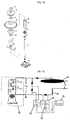
- the test apparatus shown in FIG. 13 includes a high voltage generating part 70 for generating a high voltage to apply a negative (-) direct current to a circular plate A having a diameter of 1m and to which each lightning arrester B is connected to be tested, a high voltage probe 72 connected to an output terminal of the high voltage generating part 70 to draw a voltage, a current detection part 73 connected to the output terminal of the high voltage generating part 70, a current amplification part 74 for amplifying the current output from the current detection part 73, and an oscilloscope 76 for receiving a voltage and current from the high voltage probe 72 and the current amplification part 74 to display the voltage and current.
- a high voltage generating part 70 for generating a high voltage to apply a negative (-) direct current to a circular plate A having a diameter of 1m and to which each lightning arrester B is connected to be tested
- a high voltage probe 72 connected to an output terminal of the high voltage generating part 70 to draw a voltage
- a gap d represents a distance between the circular plate A and each lightning arrester B.
- a negative (-) direct voltage output of the high voltage generating part 70 is connected to the circular plate A, and a parabola part is connected to each lightning arrester B to be tested.
- the gap d is 80cm in order to measure corona discharge current, and an output voltage of the high voltage generating part 70 is applied to a maximum voltage of 400kV. Relationship between the current and voltage due to the corona discharge is shown in FIG. 14 .
- the lightning arrester in accordance with the present invention represented as curve E has a lower application voltage with the same corona discharge current flowing in comparison with the conventional lightning arresters represented as curves A-D.
- the lightning arrester in accordance with the present invention has lower probability of lightning when a thundercloud approaches, in comparison with the conventional lightning arresters.
- lightning arresters in accordance with the present invention discharge space charges distributed in the air around a building by a thundercloud approaching the building and ground charges supplied from the ground before a lightning strike occurs, thereby blocking concentration of the ground charges to decrease the entire electric field of the building.
Landscapes
- Elimination Of Static Electricity (AREA)
Claims (15)
- Un parafoudre, comprenant
une tige conductrice (30)(50) montée à une partie supérieure d'un objet à protéger contre la foudre et connectée à un élément au sol ; et
un isolateur (34) (54) couplé à une extrémité de la tige (30)(50),
caractérisé en ce que le parafoudre comprend un tuyau de charge (45a)(65a) ayant une forme cylindrique avec des saillies en forme de goupille (45b)(65b) s'étendant vers l'intérieur de celui-ci et où des charges d'espace sont chargées, et une tige de charge insérée dans le tuyau de charge (45a)(65a) et connectée au milieu de la tige (30)(50). - Le parafoudre selon la revendication 1, où la tige de charge est connectée directement à la tige (30).
- Le parafoudre selon la revendication 1, où le tuyau de charge (45a) et la tige (30) sont connectés verticalement l'un à l'autre pour former au moins une structure bi-étagée.
- Le parafoudre selon la revendication 1, où les tiges de charge (66) et les tuyaux de charge (65a) sont radialement disposés en nombre multiple passant par une partie de connexion (50c) connecté au milieu de la tige (50).
- Le parafoudre selon la revendication 4, où les tiges de charge (66) et les tuyaux de charge (45a) sont disposés à des intervalles prédéfinis.
- Le parafoudre selon la revendication 1, comprenant en outre :un premier moyen de charge (33, 36 à 39, 41 et 42) couplé à la tige (30) en dessous de l'isolateur (34) passant par le médium d'un corps isolant et auquel des charges d'espace dans l'air sont chargées par un nuage d'orage ; etun moyen de décharge (40) couplé à la tige (30) correspondant au premier moyen de charge (33, 36 à 39, 41 et 42) et auquel des charges de terre fournies de la terre sont chargées.
- Le parafoudre selon la revendication 6, où le premier moyen de charge (33, 36 à 39, 41 et 42) se compose d'une pluralité de disques et où le moyen de décharge (40) est formé par une disque.
- Le parafoudre selon la revendication 1, où l'isolateur (34) (54) est formé par un polymère électriquement isolant.
- Le parafoudre selon la revendication 1, où une pluralité de goupilles de charge (80) est disposée à une partie supérieure du tuyau de charge (45a) de sorte que des charges d'espace dans l'air sont chargées par un nuage d'orage.
- Le parafoudre selon la revendication 9, comprenant en outre :un moyen de charge (37, 39) couplé à la tige (30) en dessous de l'isolateur (34) passant par le médium d'un corps isolant et auquel des charges d'espace dans l'air sont chargées par un nuage d'orage ; etun moyen de décharge (40) couplé à la tige (30) correspondant au moyen de charge (37, 39) et auquel des charges de terre fournies de la terre sont chargées.
- Le parafoudre selon la revendication 10, où le corps isolant et formé par du matériau diélectrique.
- Le parafoudre selon la revendication 11, où le matériau diélectrique est formé par n'importe quel matériau choisi dans le groupe comprenant le dioxyde de titane (TiO2) et le dioxyde de silicium (SiO2).
- Le parafoudre selon la revendication 10, où le moyen de charge (37, 39) a une forme de parabole inversée.
- Le parafoudre selon la revendication 10, où un côté de la goupille de charge (80) est courbé vers une surface intérieure du moyen de charge (37, 39) pour être soudé par points à la surface intérieure du moyen de charge (37, 39) à une distance polaire et où l'autre côté de la goupille de charge (80) s'étend vers une face intérieure du tuyau de charge (45a) pour être soudé par points à celui-ci.
- Le parafoudre selon la revendication 9, où l'isolateur (34) comprend en outre une bague couplée à une extrémité de la tige.
Applications Claiming Priority (3)
| Application Number | Priority Date | Filing Date | Title |
|---|---|---|---|
| KR1020060077237A KR100856719B1 (ko) | 2006-08-16 | 2006-08-16 | 피뢰장치 |
| KR1020070003648A KR100787569B1 (ko) | 2007-01-12 | 2007-01-12 | 피뢰장치 |
| PCT/KR2007/000893 WO2008020669A1 (fr) | 2006-08-16 | 2007-02-21 | Parafoudre |
Publications (3)
| Publication Number | Publication Date |
|---|---|
| EP2052446A1 EP2052446A1 (fr) | 2009-04-29 |
| EP2052446A4 EP2052446A4 (fr) | 2012-10-31 |
| EP2052446B1 true EP2052446B1 (fr) | 2016-09-07 |
Family
ID=39082181
Family Applications (1)
| Application Number | Title | Priority Date | Filing Date |
|---|---|---|---|
| EP07709042.1A Not-in-force EP2052446B1 (fr) | 2006-08-16 | 2007-02-21 | Parafoudre |
Country Status (5)
| Country | Link |
|---|---|
| US (1) | US8451575B2 (fr) |
| EP (1) | EP2052446B1 (fr) |
| JP (1) | JP4918693B2 (fr) |
| CN (1) | CN102522700B (fr) |
| WO (1) | WO2008020669A1 (fr) |
Families Citing this family (18)
| Publication number | Priority date | Publication date | Assignee | Title |
|---|---|---|---|---|
| JP5443410B2 (ja) * | 2011-03-02 | 2014-03-19 | 株式会社落雷抑制システムズ | 落雷抑制型避雷装置 |
| CN102751661B (zh) * | 2012-07-04 | 2014-05-21 | 株洲普天中普防雷科技有限公司 | 基于双电极的避雷方法和避雷针 |
| KR101496979B1 (ko) * | 2013-11-07 | 2015-03-02 | 한국산업은행 | 쌍극자 피뢰장치 |
| KR101491414B1 (ko) * | 2014-06-13 | 2015-02-06 | 정용기 | 능동형 낙뢰 수뢰장치 |
| ES2537275B1 (es) * | 2015-03-24 | 2016-02-12 | Dinnteco International, S.L. | Dispositivo equilibrador de campos eléctricos variables |
| WO2017030430A1 (fr) * | 2015-08-17 | 2017-02-23 | Daris Inženering | Parafoudre à architecture configurable modulaire et procédé lui permettant d'assurer une protection contre la foudre |
| US11609358B2 (en) | 2016-07-18 | 2023-03-21 | Omni Lps. Co., Ltd. | Lightning strike alarm system using bipolar conventional air terminal |
| KR101785024B1 (ko) | 2016-07-18 | 2017-10-13 | (주)옴니엘피에스 | 쌍극자피뢰침(BCAT: Bipolar Conventional Air Terminal)를 이용한 낙뢰경보시스템 |
| JP6885593B2 (ja) * | 2017-10-31 | 2021-06-16 | 株式会社落雷抑制システムズ | 落雷抑制型避雷器および避雷装置 |
| US11594869B2 (en) * | 2017-10-31 | 2023-02-28 | Lightning Suppression Systems Co., Ltd. | Lightning suppression type lightning discharger and arrester |
| JP7421181B2 (ja) * | 2020-10-09 | 2024-01-24 | 株式会社落雷抑制システムズ | 落雷抑制型風力発電設備 |
| CN112490997A (zh) * | 2020-12-16 | 2021-03-12 | 南京克晟圣贸易有限公司 | 一种用于避雷针的防断裂装置 |
| CN113588997B (zh) * | 2021-07-29 | 2024-08-20 | 芜湖市凯鑫避雷器有限责任公司 | 一种避雷器用带电检测装置 |
| CN116131235A (zh) * | 2023-02-02 | 2023-05-16 | 武汉华电众力电力科技有限公司 | 一种雷击限制器 |
| CN117996569B (zh) * | 2024-04-03 | 2024-05-31 | 厦门雷神电气设备有限公司 | 一种高稳定性雷达避雷针 |
| US12363817B1 (en) | 2024-06-28 | 2025-07-15 | Ray McLaine | Apparatus for collecting electrons from cloud bottoms and cloud tubes |
| CN118712888B (zh) * | 2024-08-28 | 2024-11-26 | 北京万云安德防雷工程有限公司 | 一种高层建筑用避雷针 |
| CN118970633B (zh) * | 2024-10-21 | 2025-03-25 | 福州筑福天下科技有限公司 | 用于高层建筑物的自动除尘式避雷装置 |
Family Cites Families (10)
| Publication number | Priority date | Publication date | Assignee | Title |
|---|---|---|---|---|
| JPS5866513A (ja) * | 1981-10-14 | 1983-04-20 | 関西電力株式会社 | 誘雷装置 |
| JP2704514B2 (ja) * | 1987-06-18 | 1998-01-26 | ジヨン リチヤ−ド ガムリ− | 避雷針 |
| FR2697379B1 (fr) * | 1992-10-28 | 1995-01-13 | Helita Sa | Paratonnerre à dispositif d'amorçage à décharge électrique glissante le long d'un diélectrique. |
| US6069314A (en) * | 1997-05-16 | 2000-05-30 | Varela; Manuel Domingo | Emitter of ions for a lightning rod with a parabolic reflector |
| GB9726611D0 (en) * | 1997-12-18 | 1998-02-18 | Smith Tech Dev H R | Shelters |
| US6307149B1 (en) * | 1999-09-10 | 2001-10-23 | Fcc/Enforcement Bureau | Non-contaminating lightning protection system |
| JP2005019390A (ja) * | 2003-05-30 | 2005-01-20 | Norio Murazaki | 避雷装置 |
| KR100433011B1 (ko) | 2003-06-25 | 2004-05-28 | 정용기 | 쌍극자 멀티 공간전하 분산형 피뢰장치 |
| KR100440616B1 (ko) | 2003-09-06 | 2004-07-19 | 정용기 | 피뢰장치 |
| KR100787576B1 (ko) * | 2007-01-12 | 2007-12-21 | 정용기 | 피뢰장치 |
-
2007
- 2007-02-21 CN CN2011104108670A patent/CN102522700B/zh not_active Expired - Fee Related
- 2007-02-21 WO PCT/KR2007/000893 patent/WO2008020669A1/fr not_active Ceased
- 2007-02-21 US US12/377,854 patent/US8451575B2/en not_active Expired - Fee Related
- 2007-02-21 EP EP07709042.1A patent/EP2052446B1/fr not_active Not-in-force
- 2007-02-21 JP JP2009524543A patent/JP4918693B2/ja not_active Expired - Fee Related
Also Published As
| Publication number | Publication date |
|---|---|
| HK1168943A1 (en) | 2013-01-11 |
| US20100284118A1 (en) | 2010-11-11 |
| EP2052446A4 (fr) | 2012-10-31 |
| EP2052446A1 (fr) | 2009-04-29 |
| WO2008020669A1 (fr) | 2008-02-21 |
| US8451575B2 (en) | 2013-05-28 |
| JP4918693B2 (ja) | 2012-04-18 |
| JP2010500732A (ja) | 2010-01-07 |
| CN102522700B (zh) | 2013-12-18 |
| CN102522700A (zh) | 2012-06-27 |
Similar Documents
| Publication | Publication Date | Title |
|---|---|---|
| EP2052446B1 (fr) | Parafoudre | |
| CN101981633B (zh) | 高压绝缘体和使用所述绝缘体的高压电力线 | |
| Ma et al. | Study on insulation characteristics of GIS under combined voltage of DC and lightning impulse | |
| JP5135263B2 (ja) | 密閉型絶縁装置 | |
| IL267864A (en) | Overvoltage protection for electrical systems | |
| CN101512855B (zh) | 一种避雷器 | |
| WO2008084895A1 (fr) | Parafoudre | |
| Ma et al. | Breakdown characteristics of particle-contaminated HVDC GIL under superimposed voltage of DC and impulse | |
| US9660433B2 (en) | Active lightning arrester | |
| KR101025499B1 (ko) | 평판 전극형 쌍극자 대전관 피뢰장치 | |
| TWI383556B (zh) | 避雷器 | |
| Du et al. | Effects of DC and pulse voltage combination on surface charge dynamic behaviors of epoxy resin | |
| CN209199705U (zh) | 一种带并联间隙避雷器 | |
| KR20080035556A (ko) | 피뢰장치 | |
| WO2016052830A1 (fr) | Parafoudre bipolaire revêtu d'un matériau magnétique | |
| HK1168943B (en) | Lightning arrester | |
| RU2336617C2 (ru) | Молниеотвод с ускоренной ионизацией воздуха | |
| Ma et al. | Study on flashover characteristics of insulators in SF 6 under combined voltage of DC and lightning impulse | |
| Ma et al. | Influence of operating voltage on breakdown characteristics of HVDC GIL under impulse voltage | |
| Lei et al. | Experiments and simulation research on the lightning flashover risk of UHVDC electrode lines | |
| KR20050055817A (ko) | 공간전하 분산형 피뢰장치 | |
| KR200346680Y1 (ko) | 공간전하 분산형 피뢰장치 | |
| Sangkasaad | Solid Core Suspension Disc Insulators Preventing Puncture Caused by Steep Front Surge Voltage | |
| KR101719181B1 (ko) | 안정적인 방전 및 절연이 보장되는 불활성가스가 충진된 결로방지 아크 방전봉 | |
| JPH10166909A (ja) | 電車線路の地絡保護対策用直流電流阻止装置 |
Legal Events
| Date | Code | Title | Description |
|---|---|---|---|
| PUAI | Public reference made under article 153(3) epc to a published international application that has entered the european phase |
Free format text: ORIGINAL CODE: 0009012 |
|
| 17P | Request for examination filed |
Effective date: 20090216 |
|
| AK | Designated contracting states |
Kind code of ref document: A1 Designated state(s): AT BE BG CH CY CZ DE DK EE ES FI FR GB GR HU IE IS IT LI LT LU LV MC NL PL PT RO SE SI SK TR |
|
| AX | Request for extension of the european patent |
Extension state: AL BA HR MK RS |
|
| DAX | Request for extension of the european patent (deleted) | ||
| REG | Reference to a national code |
Ref country code: DE Ref legal event code: R079 Ref document number: 602007047807 Country of ref document: DE Free format text: PREVIOUS MAIN CLASS: H01T0004000000 Ipc: H02G0013000000 |
|
| A4 | Supplementary search report drawn up and despatched |
Effective date: 20120927 |
|
| RIC1 | Information provided on ipc code assigned before grant |
Ipc: H02G 13/00 20060101AFI20120921BHEP |
|
| 17Q | First examination report despatched |
Effective date: 20130712 |
|
| RAP1 | Party data changed (applicant data changed or rights of an application transferred) |
Owner name: OMNI LPS. CO., LTD. |
|
| RIN1 | Information on inventor provided before grant (corrected) |
Inventor name: OMNI LPS. CO., LTD. |
|
| RAP1 | Party data changed (applicant data changed or rights of an application transferred) |
Owner name: THE KOREA DEVELOPMENT BANK |
|
| RIN1 | Information on inventor provided before grant (corrected) |
Inventor name: THE KOREA DEVELOPMENT BANK |
|
| GRAP | Despatch of communication of intention to grant a patent |
Free format text: ORIGINAL CODE: EPIDOSNIGR1 |
|
| INTG | Intention to grant announced |
Effective date: 20160314 |
|
| GRAS | Grant fee paid |
Free format text: ORIGINAL CODE: EPIDOSNIGR3 |
|
| GRAA | (expected) grant |
Free format text: ORIGINAL CODE: 0009210 |
|
| RIN1 | Information on inventor provided before grant (corrected) |
Inventor name: CHUNG, YOUNG-KI |
|
| AK | Designated contracting states |
Kind code of ref document: B1 Designated state(s): AT BE BG CH CY CZ DE DK EE ES FI FR GB GR HU IE IS IT LI LT LU LV MC NL PL PT RO SE SI SK TR |
|
| REG | Reference to a national code |
Ref country code: GB Ref legal event code: FG4D |
|
| REG | Reference to a national code |
Ref country code: CH Ref legal event code: EP |
|
| REG | Reference to a national code |
Ref country code: IE Ref legal event code: FG4D |
|
| REG | Reference to a national code |
Ref country code: DE Ref legal event code: R096 Ref document number: 602007047807 Country of ref document: DE |
|
| REG | Reference to a national code |
Ref country code: AT Ref legal event code: REF Ref document number: 827612 Country of ref document: AT Kind code of ref document: T Effective date: 20161015 |
|
| REG | Reference to a national code |
Ref country code: LT Ref legal event code: MG4D |
|
| REG | Reference to a national code |
Ref country code: NL Ref legal event code: MP Effective date: 20160907 |
|
| PG25 | Lapsed in a contracting state [announced via postgrant information from national office to epo] |
Ref country code: FI Free format text: LAPSE BECAUSE OF FAILURE TO SUBMIT A TRANSLATION OF THE DESCRIPTION OR TO PAY THE FEE WITHIN THE PRESCRIBED TIME-LIMIT Effective date: 20160907 Ref country code: LT Free format text: LAPSE BECAUSE OF FAILURE TO SUBMIT A TRANSLATION OF THE DESCRIPTION OR TO PAY THE FEE WITHIN THE PRESCRIBED TIME-LIMIT Effective date: 20160907 |
|
| REG | Reference to a national code |
Ref country code: AT Ref legal event code: MK05 Ref document number: 827612 Country of ref document: AT Kind code of ref document: T Effective date: 20160907 |
|
| PG25 | Lapsed in a contracting state [announced via postgrant information from national office to epo] |
Ref country code: NL Free format text: LAPSE BECAUSE OF FAILURE TO SUBMIT A TRANSLATION OF THE DESCRIPTION OR TO PAY THE FEE WITHIN THE PRESCRIBED TIME-LIMIT Effective date: 20160907 Ref country code: SE Free format text: LAPSE BECAUSE OF FAILURE TO SUBMIT A TRANSLATION OF THE DESCRIPTION OR TO PAY THE FEE WITHIN THE PRESCRIBED TIME-LIMIT Effective date: 20160907 Ref country code: ES Free format text: LAPSE BECAUSE OF FAILURE TO SUBMIT A TRANSLATION OF THE DESCRIPTION OR TO PAY THE FEE WITHIN THE PRESCRIBED TIME-LIMIT Effective date: 20160907 Ref country code: LV Free format text: LAPSE BECAUSE OF FAILURE TO SUBMIT A TRANSLATION OF THE DESCRIPTION OR TO PAY THE FEE WITHIN THE PRESCRIBED TIME-LIMIT Effective date: 20160907 Ref country code: GR Free format text: LAPSE BECAUSE OF FAILURE TO SUBMIT A TRANSLATION OF THE DESCRIPTION OR TO PAY THE FEE WITHIN THE PRESCRIBED TIME-LIMIT Effective date: 20161208 |
|
| PG25 | Lapsed in a contracting state [announced via postgrant information from national office to epo] |
Ref country code: RO Free format text: LAPSE BECAUSE OF FAILURE TO SUBMIT A TRANSLATION OF THE DESCRIPTION OR TO PAY THE FEE WITHIN THE PRESCRIBED TIME-LIMIT Effective date: 20160907 Ref country code: EE Free format text: LAPSE BECAUSE OF FAILURE TO SUBMIT A TRANSLATION OF THE DESCRIPTION OR TO PAY THE FEE WITHIN THE PRESCRIBED TIME-LIMIT Effective date: 20160907 |
|
| PG25 | Lapsed in a contracting state [announced via postgrant information from national office to epo] |
Ref country code: AT Free format text: LAPSE BECAUSE OF FAILURE TO SUBMIT A TRANSLATION OF THE DESCRIPTION OR TO PAY THE FEE WITHIN THE PRESCRIBED TIME-LIMIT Effective date: 20160907 Ref country code: SK Free format text: LAPSE BECAUSE OF FAILURE TO SUBMIT A TRANSLATION OF THE DESCRIPTION OR TO PAY THE FEE WITHIN THE PRESCRIBED TIME-LIMIT Effective date: 20160907 Ref country code: IS Free format text: LAPSE BECAUSE OF FAILURE TO SUBMIT A TRANSLATION OF THE DESCRIPTION OR TO PAY THE FEE WITHIN THE PRESCRIBED TIME-LIMIT Effective date: 20170107 Ref country code: BE Free format text: LAPSE BECAUSE OF FAILURE TO SUBMIT A TRANSLATION OF THE DESCRIPTION OR TO PAY THE FEE WITHIN THE PRESCRIBED TIME-LIMIT Effective date: 20160907 Ref country code: CZ Free format text: LAPSE BECAUSE OF FAILURE TO SUBMIT A TRANSLATION OF THE DESCRIPTION OR TO PAY THE FEE WITHIN THE PRESCRIBED TIME-LIMIT Effective date: 20160907 Ref country code: PL Free format text: LAPSE BECAUSE OF FAILURE TO SUBMIT A TRANSLATION OF THE DESCRIPTION OR TO PAY THE FEE WITHIN THE PRESCRIBED TIME-LIMIT Effective date: 20160907 Ref country code: BG Free format text: LAPSE BECAUSE OF FAILURE TO SUBMIT A TRANSLATION OF THE DESCRIPTION OR TO PAY THE FEE WITHIN THE PRESCRIBED TIME-LIMIT Effective date: 20161207 Ref country code: PT Free format text: LAPSE BECAUSE OF FAILURE TO SUBMIT A TRANSLATION OF THE DESCRIPTION OR TO PAY THE FEE WITHIN THE PRESCRIBED TIME-LIMIT Effective date: 20170109 |
|
| PGFP | Annual fee paid to national office [announced via postgrant information from national office to epo] |
Ref country code: GB Payment date: 20170327 Year of fee payment: 11 |
|
| REG | Reference to a national code |
Ref country code: DE Ref legal event code: R097 Ref document number: 602007047807 Country of ref document: DE |
|
| PG25 | Lapsed in a contracting state [announced via postgrant information from national office to epo] |
Ref country code: IT Free format text: LAPSE BECAUSE OF FAILURE TO SUBMIT A TRANSLATION OF THE DESCRIPTION OR TO PAY THE FEE WITHIN THE PRESCRIBED TIME-LIMIT Effective date: 20160907 |
|
| PLBE | No opposition filed within time limit |
Free format text: ORIGINAL CODE: 0009261 |
|
| STAA | Information on the status of an ep patent application or granted ep patent |
Free format text: STATUS: NO OPPOSITION FILED WITHIN TIME LIMIT |
|
| PG25 | Lapsed in a contracting state [announced via postgrant information from national office to epo] |
Ref country code: DK Free format text: LAPSE BECAUSE OF FAILURE TO SUBMIT A TRANSLATION OF THE DESCRIPTION OR TO PAY THE FEE WITHIN THE PRESCRIBED TIME-LIMIT Effective date: 20160907 |
|
| PGFP | Annual fee paid to national office [announced via postgrant information from national office to epo] |
Ref country code: DE Payment date: 20170328 Year of fee payment: 11 |
|
| 26N | No opposition filed |
Effective date: 20170608 |
|
| PG25 | Lapsed in a contracting state [announced via postgrant information from national office to epo] |
Ref country code: SI Free format text: LAPSE BECAUSE OF FAILURE TO SUBMIT A TRANSLATION OF THE DESCRIPTION OR TO PAY THE FEE WITHIN THE PRESCRIBED TIME-LIMIT Effective date: 20160907 |
|
| PG25 | Lapsed in a contracting state [announced via postgrant information from national office to epo] |
Ref country code: MC Free format text: LAPSE BECAUSE OF FAILURE TO SUBMIT A TRANSLATION OF THE DESCRIPTION OR TO PAY THE FEE WITHIN THE PRESCRIBED TIME-LIMIT Effective date: 20160907 |
|
| REG | Reference to a national code |
Ref country code: CH Ref legal event code: PL |
|
| PG25 | Lapsed in a contracting state [announced via postgrant information from national office to epo] |
Ref country code: LI Free format text: LAPSE BECAUSE OF NON-PAYMENT OF DUE FEES Effective date: 20170228 Ref country code: CH Free format text: LAPSE BECAUSE OF NON-PAYMENT OF DUE FEES Effective date: 20170228 |
|
| REG | Reference to a national code |
Ref country code: IE Ref legal event code: MM4A |
|
| REG | Reference to a national code |
Ref country code: FR Ref legal event code: ST Effective date: 20171031 |
|
| PG25 | Lapsed in a contracting state [announced via postgrant information from national office to epo] |
Ref country code: LU Free format text: LAPSE BECAUSE OF NON-PAYMENT OF DUE FEES Effective date: 20170221 |
|
| PG25 | Lapsed in a contracting state [announced via postgrant information from national office to epo] |
Ref country code: FR Free format text: LAPSE BECAUSE OF NON-PAYMENT OF DUE FEES Effective date: 20170228 |
|
| PG25 | Lapsed in a contracting state [announced via postgrant information from national office to epo] |
Ref country code: IE Free format text: LAPSE BECAUSE OF NON-PAYMENT OF DUE FEES Effective date: 20170221 |
|
| REG | Reference to a national code |
Ref country code: DE Ref legal event code: R119 Ref document number: 602007047807 Country of ref document: DE |
|
| GBPC | Gb: european patent ceased through non-payment of renewal fee |
Effective date: 20180221 |
|
| PG25 | Lapsed in a contracting state [announced via postgrant information from national office to epo] |
Ref country code: DE Free format text: LAPSE BECAUSE OF NON-PAYMENT OF DUE FEES Effective date: 20180901 |
|
| PG25 | Lapsed in a contracting state [announced via postgrant information from national office to epo] |
Ref country code: GB Free format text: LAPSE BECAUSE OF NON-PAYMENT OF DUE FEES Effective date: 20180221 |
|
| PG25 | Lapsed in a contracting state [announced via postgrant information from national office to epo] |
Ref country code: HU Free format text: LAPSE BECAUSE OF FAILURE TO SUBMIT A TRANSLATION OF THE DESCRIPTION OR TO PAY THE FEE WITHIN THE PRESCRIBED TIME-LIMIT; INVALID AB INITIO Effective date: 20070221 |
|
| PG25 | Lapsed in a contracting state [announced via postgrant information from national office to epo] |
Ref country code: CY Free format text: LAPSE BECAUSE OF NON-PAYMENT OF DUE FEES Effective date: 20160907 |
|
| PG25 | Lapsed in a contracting state [announced via postgrant information from national office to epo] |
Ref country code: TR Free format text: LAPSE BECAUSE OF FAILURE TO SUBMIT A TRANSLATION OF THE DESCRIPTION OR TO PAY THE FEE WITHIN THE PRESCRIBED TIME-LIMIT Effective date: 20160907 |