EP2052659B1 - Appareil de séparation cyclonique - Google Patents
Appareil de séparation cyclonique Download PDFInfo
- Publication number
- EP2052659B1 EP2052659B1 EP08275064.7A EP08275064A EP2052659B1 EP 2052659 B1 EP2052659 B1 EP 2052659B1 EP 08275064 A EP08275064 A EP 08275064A EP 2052659 B1 EP2052659 B1 EP 2052659B1
- Authority
- EP
- European Patent Office
- Prior art keywords
- stage
- cyclone
- cyclonic separation
- separation apparatus
- stages
- Prior art date
- Legal status (The legal status is an assumption and is not a legal conclusion. Google has not performed a legal analysis and makes no representation as to the accuracy of the status listed.)
- Not-in-force
Links
- 238000000926 separation method Methods 0.000 title claims description 64
- JTJMJGYZQZDUJJ-UHFFFAOYSA-N phencyclidine Chemical class C1CCCCN1C1(C=2C=CC=CC=2)CCCCC1 JTJMJGYZQZDUJJ-UHFFFAOYSA-N 0.000 claims description 47
- 238000011144 upstream manufacturing Methods 0.000 claims description 21
- 239000011236 particulate material Substances 0.000 claims description 13
- 239000012530 fluid Substances 0.000 claims description 10
- 238000010276 construction Methods 0.000 claims description 3
- 239000000428 dust Substances 0.000 description 6
- 239000002245 particle Substances 0.000 description 4
- 230000003292 diminished effect Effects 0.000 description 3
- 239000000463 material Substances 0.000 description 3
- 238000004140 cleaning Methods 0.000 description 2
- 238000000034 method Methods 0.000 description 1
- 230000002093 peripheral effect Effects 0.000 description 1
- 230000007704 transition Effects 0.000 description 1
Images

Classifications
-
- A—HUMAN NECESSITIES
- A47—FURNITURE; DOMESTIC ARTICLES OR APPLIANCES; COFFEE MILLS; SPICE MILLS; SUCTION CLEANERS IN GENERAL
- A47L—DOMESTIC WASHING OR CLEANING; SUCTION CLEANERS IN GENERAL
- A47L9/00—Details or accessories of suction cleaners, e.g. mechanical means for controlling the suction or for effecting pulsating action; Storing devices specially adapted to suction cleaners or parts thereof; Carrying-vehicles specially adapted for suction cleaners
- A47L9/10—Filters; Dust separators; Dust removal; Automatic exchange of filters
- A47L9/16—Arrangement or disposition of cyclones or other devices with centrifugal action
-
- A—HUMAN NECESSITIES
- A47—FURNITURE; DOMESTIC ARTICLES OR APPLIANCES; COFFEE MILLS; SPICE MILLS; SUCTION CLEANERS IN GENERAL
- A47L—DOMESTIC WASHING OR CLEANING; SUCTION CLEANERS IN GENERAL
- A47L9/00—Details or accessories of suction cleaners, e.g. mechanical means for controlling the suction or for effecting pulsating action; Storing devices specially adapted to suction cleaners or parts thereof; Carrying-vehicles specially adapted for suction cleaners
- A47L9/10—Filters; Dust separators; Dust removal; Automatic exchange of filters
- A47L9/16—Arrangement or disposition of cyclones or other devices with centrifugal action
- A47L9/1616—Multiple arrangement thereof
-
- A—HUMAN NECESSITIES
- A47—FURNITURE; DOMESTIC ARTICLES OR APPLIANCES; COFFEE MILLS; SPICE MILLS; SUCTION CLEANERS IN GENERAL
- A47L—DOMESTIC WASHING OR CLEANING; SUCTION CLEANERS IN GENERAL
- A47L9/00—Details or accessories of suction cleaners, e.g. mechanical means for controlling the suction or for effecting pulsating action; Storing devices specially adapted to suction cleaners or parts thereof; Carrying-vehicles specially adapted for suction cleaners
- A47L9/10—Filters; Dust separators; Dust removal; Automatic exchange of filters
- A47L9/16—Arrangement or disposition of cyclones or other devices with centrifugal action
- A47L9/1616—Multiple arrangement thereof
- A47L9/1625—Multiple arrangement thereof for series flow
-
- A—HUMAN NECESSITIES
- A47—FURNITURE; DOMESTIC ARTICLES OR APPLIANCES; COFFEE MILLS; SPICE MILLS; SUCTION CLEANERS IN GENERAL
- A47L—DOMESTIC WASHING OR CLEANING; SUCTION CLEANERS IN GENERAL
- A47L9/00—Details or accessories of suction cleaners, e.g. mechanical means for controlling the suction or for effecting pulsating action; Storing devices specially adapted to suction cleaners or parts thereof; Carrying-vehicles specially adapted for suction cleaners
- A47L9/10—Filters; Dust separators; Dust removal; Automatic exchange of filters
- A47L9/16—Arrangement or disposition of cyclones or other devices with centrifugal action
- A47L9/1616—Multiple arrangement thereof
- A47L9/1625—Multiple arrangement thereof for series flow
- A47L9/1633—Concentric cyclones
-
- A—HUMAN NECESSITIES
- A47—FURNITURE; DOMESTIC ARTICLES OR APPLIANCES; COFFEE MILLS; SPICE MILLS; SUCTION CLEANERS IN GENERAL
- A47L—DOMESTIC WASHING OR CLEANING; SUCTION CLEANERS IN GENERAL
- A47L9/00—Details or accessories of suction cleaners, e.g. mechanical means for controlling the suction or for effecting pulsating action; Storing devices specially adapted to suction cleaners or parts thereof; Carrying-vehicles specially adapted for suction cleaners
- A47L9/10—Filters; Dust separators; Dust removal; Automatic exchange of filters
- A47L9/16—Arrangement or disposition of cyclones or other devices with centrifugal action
- A47L9/1616—Multiple arrangement thereof
- A47L9/1641—Multiple arrangement thereof for parallel flow
-
- B—PERFORMING OPERATIONS; TRANSPORTING
- B04—CENTRIFUGAL APPARATUS OR MACHINES FOR CARRYING-OUT PHYSICAL OR CHEMICAL PROCESSES
- B04C—APPARATUS USING FREE VORTEX FLOW, e.g. CYCLONES
- B04C5/00—Apparatus in which the axial direction of the vortex is reversed
- B04C5/24—Multiple arrangement thereof
-
- B—PERFORMING OPERATIONS; TRANSPORTING
- B04—CENTRIFUGAL APPARATUS OR MACHINES FOR CARRYING-OUT PHYSICAL OR CHEMICAL PROCESSES
- B04C—APPARATUS USING FREE VORTEX FLOW, e.g. CYCLONES
- B04C5/00—Apparatus in which the axial direction of the vortex is reversed
- B04C5/24—Multiple arrangement thereof
- B04C5/26—Multiple arrangement thereof for series flow
-
- B—PERFORMING OPERATIONS; TRANSPORTING
- B04—CENTRIFUGAL APPARATUS OR MACHINES FOR CARRYING-OUT PHYSICAL OR CHEMICAL PROCESSES
- B04C—APPARATUS USING FREE VORTEX FLOW, e.g. CYCLONES
- B04C5/00—Apparatus in which the axial direction of the vortex is reversed
- B04C5/24—Multiple arrangement thereof
- B04C5/28—Multiple arrangement thereof for parallel flow
-
- B—PERFORMING OPERATIONS; TRANSPORTING
- B04—CENTRIFUGAL APPARATUS OR MACHINES FOR CARRYING-OUT PHYSICAL OR CHEMICAL PROCESSES
- B04C—APPARATUS USING FREE VORTEX FLOW, e.g. CYCLONES
- B04C7/00—Apparatus not provided for in group B04C1/00, B04C3/00, or B04C5/00; Multiple arrangements not provided for in one of the groups B04C1/00, B04C3/00, or B04C5/00; Combinations of apparatus covered by two or more of the groups B04C1/00, B04C3/00, or B04C5/00
-
- Y—GENERAL TAGGING OF NEW TECHNOLOGICAL DEVELOPMENTS; GENERAL TAGGING OF CROSS-SECTIONAL TECHNOLOGIES SPANNING OVER SEVERAL SECTIONS OF THE IPC; TECHNICAL SUBJECTS COVERED BY FORMER USPC CROSS-REFERENCE ART COLLECTIONS [XRACs] AND DIGESTS
- Y10—TECHNICAL SUBJECTS COVERED BY FORMER USPC
- Y10S—TECHNICAL SUBJECTS COVERED BY FORMER USPC CROSS-REFERENCE ART COLLECTIONS [XRACs] AND DIGESTS
- Y10S55/00—Gas separation
- Y10S55/03—Vacuum cleaner
Definitions
- the present invention relates to cyclonic separation apparatus and particularly, but not exclusively, to cyclonic separation apparatus for use in vacuum cleaners.
- High separation efficiency cyclonic separation is generally achieved by connecting several separation stages in series.
- the successive stages are typically arranged in increasing efficiency in the direction of gas flow, although it is known to provide adjacent stages of similar efficiency.
- GB2424603 discloses a three-stage separator comprising a low-efficiency cylindrical cyclone as the first stage, an annular array of parallel-connected high-efficiency cyclones located in a chamber above the first stage and a second similar array of high-efficiency cyclones as the third stage located in a chamber above the second stage.
- the height of this arrangement renders it of limited use to vacuum cleaners, where compact dimensions are required.
- the respective separation stages discharge their separated material into three separate collection chambers located below the respective cyclone outlets.
- the collection chambers must be emptied individually, which can be a time consuming process since several parts are required to be removed from the separator unit.
- GB2424606 discloses a multi-stage cyclonic separator for a vacuum cleaner whereby the high efficiency mini-cyclones of the second and third stages are arranged around the periphery of the of the low-efficiency first stage cyclone.
- the peripheral arrangement of the higher-efficiency stages is restrictive of the number of cyclones possible in the individual stages, having regard to the dimensional limitations applicable to vacuum cleaners.
- US2372514 discloses three vertically stacked separation stages, but incorporates a separated material collection arrangement whereby material falling from the cyclone outlets is collected in funnels and ducted to a single outlet at the base of the separation unit.
- the second separation stage of this separator comprises an annular array of eight conical cyclones surrounding a central core tube, and the third stage comprises twenty-four small cyclones arranged in a cluster.
- a cyclonic separation apparatus comprising a plurality of series-connected separation stages, each of the separation stages comprising a plurality of cyclone separators connected in parallel and disposed in a generally annular arrangement about a main axis of the apparatus with their respective longitudinal cyclone axes extending parallel to said main axis, whereby successive separation stages in the direction of fluid flow are disposed radially inwardly of each other with respect to said main axis of the apparatus.
- the multi-stage, series connected cyclone separators of the apparatus provide a high separation efficiency, yet the annular arrangement of the stages makes the device compact and enables the apparatus to be utilised in a vacuum cleaner.
- each cyclone separator comprises a first end having a first outlet for fluid from which particulate material has been separated, a second end having a second outlet for separated particulate material, and an inlet for particulate-laden fluid located adjacent said first end.
- the first end of the cyclone separators in a said series-connected separation stage are longitudinally offset with respect to the first end of the cyclone separators in the separation stage disposed immediately upstream thereof, such that the first outlets of the cyclone separators of the upstream stage are substantially radially in line with the inlets of the cyclone separators of the adjoining downstream stage.
- each stage is connected to respective collection chambers, preferably being annular in construction and preferably being concentrically-nested.
- the collection chamber of the most upstream of said series-connected separation stages is surrounded by an annular separation chamber of a further cyclone separator connected upstream of the first of said series-connected separation stages.
- said further cyclone separator comprises a first end having a first outlet for fluid from which particulate material has been separated, a second end having a region for collecting separated particulate material, and an inlet for particulate-laden fluid located adjacent said first end, said first outlet of said further cyclone separator being connected to the inlets the cyclone separators of the upstream stage by one or more axially extending ducts, which are preferably disposed immediately inside the outer wall of the separator unit.
- the separator unit comprises a base having a hinged or otherwise openable closure which, when opened, permits separated particulate material to be emptied from each of said stages simultaneously.
- the closure further permits separated particulate material to be emptied from the collection region at the second end of the further cyclone.
- the most downstream separation stage comprises a cluster of parallel-connected cyclones.
- FIG. 1 of the drawings there is shown a cyclonic separation apparatus 1 according to the present invention for use in a vacuum cleaner.
- the separation apparatus is mounted to a chassis (not shown) incorporating a handle, the lower end of the chassis being pivotally interconnected to a wheeled floor-cleaning head incorporating a rotatable agitator brush.
- the separation apparatus 1 comprises a generally cylindrical upright housing, which houses upstream and downstream separation stages 2, 3 at its lower and upper ends respectively.
- the upstream stage 2 comprises a single low efficiency cyclone having a tubular side wall 4 defining a circular-section cyclone chamber 5.
- the lower end of the tubular side wall 4 is provided with a closure 6, which can be opened to allow separated dirt and dust to be emptied from the apparatus 1.
- An inlet duct 7 for carrying dirt and dust laden air from the floor cleaning head extends tangentially through the upper end of the tubular side wall 4 of the upstream stage 2.
- An elongate tubular container 8 extends through the cyclone chamber 5 along the centre axis thereof. The lower end of the container 8 is sealingly closed by a seal 9, which is mounted to the closure 6 such that the lower end of the container 8 is also opened when the closure 6 is opened.
- the upper end of the upstream stage 2 is closed by an annular end wall 10 having a central aperture 11, through which the tubular container 8 extends.
- a perforated shroud 12 depends from the upper end wall into the cyclone chamber 13, the lower end of the shroud being sealed against the external surface of the tubular container 8.
- the upper end of the container 8 extends into the downstream stage 3 about a transition section 13 whereby the container increases in diameter in moving from the upstream separation stage 2 to the downstream stage 3.
- the tubular container 8 defines an annular cavity or duct 14 which extends circumferentially of the apparatus 1, with the upper end of the duct 14 defining the inlet 15 to the downstream separation stage 3.
- the downstream separation stage 3 comprises a first stage 50 having a plurality of parallel connected high efficiency cyclones 16 arranged in an annular configuration.
- Each cyclone 16 of the first downstream stage 50 comprises a radially directed inlet 15 connected to the outlet of the upstream separation stage 2 via said annular cavity or duct 14.
- the cyclones 16 of the first downstream stage 50 each comprise a frustro-conical side wall 17 which extends downwardly from the inlet 15 and tapers to a small diameter, with the base of the side wall 17 defining an outlet 18 disposed substantially above the tapered section 13 of the annular container 8.
- the cyclones 16 extend longitudinally of the apparatus 1, between the annular container 8 and a central cylindrical container 19.
- the central cylindrical container 19 extends from the closure 6 mounted to the base of the cyclone chamber 5 of the upstream stage 2 to a position above the inlet 15 to the first plurality of cyclones 16.
- An outlet 20, defined by a tubular wall 21, depends from an upper wall of each of the cyclones 16 of the first downstream stage 50.
- the outlets 20 of the cyclones 16 of the first downstream stage 50 are connected in parallel to the inlets 22 of higher efficiency cyclones 23 of a second downstream stage 51, which is arranged within the annular configuration of the first downstream stage 50.
- the inlet 22 of each cyclone 23 is arranged above the outlets 20 of the first downstream stage 50 and directs the partly cleaned air radially inwardly toward the cyclones 23.
- the staggered arrangement of the first and second downstream stages 50,51 permits efficient inter-stage gas flow, thereby reducing the pressure drop associated with vertical ducts which typically connect adjacent separation stages. Also the arrangement allows successive stages to be nested closely together without the need to allow room for interconnecting ducts between the sidewalls of cyclones of successive stages.
- the cyclones 23 of the second downstream stage 51 are clustered together in an annular group about the central longitudinal axis of the apparatus 1 and are nested within the first plurality of cyclones 16.
- Each of the cyclones 23 of the second downstream stage 51 is fed air that has been partly cleaned, initially by the single low efficiency cyclone of the upstream stage 2 and then by the cyclones 16 of the first downstream stage 50.
- the inlets 22 of the cyclones 23 of the second downstream stage 51 extend radially inwardly with respect to the cyclones 16 of the first downstream stage 50.
- the cyclones 23 of the second downstream stage 51 each comprise a frustro-conical side wall 24 which extends down from the inlet 22 and tapers to a small diameter with the base of the side wall 24 defining an outlet 25.
- the cyclones 23 of the second downstream stage 51 extend longitudinally of the apparatus 1 and are disposed within the confines of the tubular container 19.
- An outlet 26, defined by a tubular wall 27, extends from an upper wall of each of each cyclone 23 of the second downstream stage 51.
- the outlets 26 extends into a chamber 28 which comprises an impeller (not shown) for drawing dust and dirt laden air into the apparatus 1 through the inlet 7, and a filter 29, which is used to remove any residual particles of dust or dirt from the air, before being vented out of the apparatus 1 through an exhaust duct 30.
- the impeller creates an airflow through the upstream and downstream stages 2, 3 from the dirty air inlet 7.
- the tangential orientation of the inlet 7 with respect to the wall 4 creates a cyclonic air flow inside the chamber 5 of the upstream stage 2, whereby air spirals downwardly around the chamber 5 towards its lower end.
- the volume of air in the spiral flow is constantly being diminished by virtue of it having been drawn radially through the perforated shroud 12 towards the downstream separation stage 3.
- the partly cleaned air flowing through the perforated shroud 12 is drawn upwardly through duct 14 and subsequently passes around the periphery of the apparatus and enters the cyclones 16 of the first downstream stage 50 via inlet 15.
- the tangential orientation of the inlet 15 to the tubular walls 17 of the cyclones 16 creates a cyclonic air flow inside each cyclone 16, whereby air spirals downwardly around the cyclone chamber towards its lower end.
- the volume of air in the spiral flow is constantly being diminished by virtue of it having been drawn radially inwardly and axially upwardly through the outlet 20 towards the cyclones 23 of the second downstream stage 51.
- the denser particles in the rotating airflow within the cyclones 16 strike the frusto-conical wall 17 of the cyclones 16 and fall through the outlets 18 into the base of the apparatus 1, between the tubular-walled containers 8 and 19.
- the partly cleaned air drawn up through the outlets 20 is subsequently passed into the inlet 22 which directs air tangentially into the cyclones 23.
- the volume of air in the spiral flow is constantly being diminished by virtue of it having been drawn radially inwardly and axially upwardly through the outlets 26 by the cyclones 23.
- Any light particles of dust remaining in the airflow have too much inertia to follow the very tight curve of the airflow and strike the frustro-conical wall 24 of the cyclones 23 and fall downwardly through the outlets 25 into the base of the apparatus 1 within the tubular-walled container 19. It will be appreciated that the dust separated by both the upstream and downstream stages 2, 3 can be emptied by removing the closure 6.
- the cleaned air is subsequently drawn from the cyclones 23 through the outlets 26 and is passed through a filter 29 arranged within the chamber 28, before passing out of the apparatus 1.
- the cyclones 23 of the second downstream stage 51 are staggered upwardly along the vertical central axis of the apparatus 1 with respect to the cyclones 16 of the first downstream stage 50, with the cyclones 23 disposed closer to the central axis of the apparatus being arranged above the cyclones 16 disposed further from the central axis.
- the cyclones of the first downstream stage may be connected to the cyclones of the second downstream stage via one or more intermediate stages, each comprising an annular array of parallel-connected cyclones staggered upwardly along the vertical central axis of the apparatus.
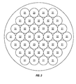
- FIG 2 there is shown a plan view of the downstream separation stage of a cyclonic separation apparatus in accordance with a third embodiment of the present invention, with the downstream separation stage comprising three levels of cyclonic separation.
- the downstream separation stage comprises:
- the cyclones 31, 32, 33 of the first, second and third downstream stages are staggered longitudinally of the apparatus 1, with those cyclones arranged closer to the central longitudinal axis of the apparatus 1 being disposed above those cyclones arranged further from the central axis.
- a cyclonic separation apparatus in accordance with the present invention is relatively simple in construction, yet has substantially improved separation efficiency by enabling large numbers of high-efficiency cyclones to be compactly accommodated.
Landscapes
- Engineering & Computer Science (AREA)
- Mechanical Engineering (AREA)
- Cyclones (AREA)
- Filters For Electric Vacuum Cleaners (AREA)
Claims (12)
- Appareil de séparation cyclonique comprenant une pluralité d'étages de séparation raccordés en série (50, 51), chacun des étages de séparation comprenant une pluralité de séparateurs à cyclone (16, 23) raccordés en parallèle et disposés dans un agencement généralement annulaire autour d'un axe principal de l'appareil, avec leurs axes de cyclone longitudinaux respectifs qui s'étendent parallèlement audit axe principal, caractérisé en ce que les étages de séparation successifs (50, 51) dans la direction de l'écoulement de fluide sont disposés radialement vers l'intérieur les uns des autres par rapport audit axe principal de l'appareil.
- Appareil de séparation cyclonique selon la revendication 1, dans lequel chaque séparateur à cyclone comprend une première extrémité ayant une première sortie pour le fluide duquel la matière particulaire a été séparée, une seconde extrémité ayant une seconde sortie pour la matière particulaire séparée, et une entrée pour le fluide chargé de particules en suspension, positionnée de manière adjacente à ladite première extrémité.
- Appareil de séparation cyclonique selon la revendication 2, dans lequel la première extrémité des séparateurs à cyclone dans ledit étage de séparation raccordé en série est longitudinalement décalée par rapport à la première extrémité des séparateurs à cyclone dans l'étage de séparation disposé immédiatement en amont, de sorte que les premières sorties des séparateurs à cyclone de l'étage en amont sont sensiblement radialement alignées avec les entrées des séparateurs à cyclone de l'étage en aval attenant.
- Appareil de séparation cyclonique selon les revendications 2 ou 3, dans lequel les sorties de chaque étage sont raccordées aux chambres de collecte respectives.
- Appareil de séparation cyclonique selon la revendication 4, dans lequel les chambres de collecte ont une construction annulaire.
- Appareil de séparation cyclonique selon les revendications 4 ou 5, dans lequel les chambres de collecte sont emboîtées de manière concentrique.
- Appareil de séparation cyclonique selon l'une quelconque des revendications 4 à 6, dans lequel la chambre de collecte dudit étage le plus en amont desdits étages de séparation raccordés en série est entourée par une chambre de séparation annulaire d'un autre séparateur à cyclone raccordé en amont du premier étage desdits étages de séparation raccordés en série.
- Appareil de séparation cyclonique selon la revendication 7, dans lequel ledit séparateur à cyclone supplémentaire comprend une première extrémité ayant une première sortie pour le fluide duquel la matière particulaire a été séparée, une seconde extrémité ayant une région pour collecter la matière particulaire séparée, et une entrée pour le fluide chargé de particules, positionnée de manière adjacente à ladite première extrémité, ladite première sortie dudit séparateur à cyclone supplémentaire étant raccordée aux entrées des séparateurs à cyclone de l'étage en amont par un ou plusieurs conduits s'étendant de manière axiale.
- Appareil de séparation cyclonique selon la revendication 8, dans lequel les conduits sont disposés immédiatement à l'intérieur d'une paroi externe de l'appareil.
- Appareil de séparation cyclonique selon l'une quelconque des revendications précédentes, comprenant une base ayant une fermeture articulée ou bien pouvant s'ouvrir qui, lorsqu'elle est ouverte, permet à la matière particulaire séparée d'être vidée de chacun desdits étages simultanément, dans lequel de préférence la fermeture permet en outre de vider la matière particulaire séparée de la région de collecte au niveau de la seconde extrémité du cyclone supplémentaire.
- Appareil de séparation cyclonique selon l'une quelconque des revendications 7 à 9, comprenant une base ayant une fermeture articulée ou bien pouvant s'ouvrir qui, lorsqu'elle est ouverte, permet de vider la matière particulaire séparée de chacun desdits étages et de la chambre de collecte au niveau de la seconde extrémité du cyclone supplémentaire simultanément.
- Appareil de séparation cyclonique selon l'une quelconque des revendications précédentes, dans lequel l'étage de séparation le plus en aval comprend un groupe de cyclones raccordés en parallèle.
Applications Claiming Priority (1)
| Application Number | Priority Date | Filing Date | Title |
|---|---|---|---|
| GB0720699.8A GB2453949B (en) | 2007-10-23 | 2007-10-23 | Cyclonic separation apparatus |
Publications (3)
| Publication Number | Publication Date |
|---|---|
| EP2052659A2 EP2052659A2 (fr) | 2009-04-29 |
| EP2052659A3 EP2052659A3 (fr) | 2010-08-04 |
| EP2052659B1 true EP2052659B1 (fr) | 2013-06-19 |
Family
ID=38829729
Family Applications (1)
| Application Number | Title | Priority Date | Filing Date |
|---|---|---|---|
| EP08275064.7A Not-in-force EP2052659B1 (fr) | 2007-10-23 | 2008-10-16 | Appareil de séparation cyclonique |
Country Status (5)
| Country | Link |
|---|---|
| US (1) | US7976597B2 (fr) |
| EP (1) | EP2052659B1 (fr) |
| CN (1) | CN101416849B (fr) |
| AU (1) | AU2008230035B2 (fr) |
| GB (1) | GB2453949B (fr) |
Families Citing this family (73)
| Publication number | Priority date | Publication date | Assignee | Title |
|---|---|---|---|---|
| GB2426726B (en) * | 2005-05-27 | 2008-11-05 | Dyson Technology Ltd | Cyclonic separating apparatus |
| BRPI0815055B1 (pt) * | 2007-07-30 | 2019-10-29 | Merpro Tortek Ltd | aparelho de ciclone |
| GB2475312B (en) * | 2009-11-16 | 2014-01-08 | Dyson Technology Ltd | A surface treating appliance |
| KR101670341B1 (ko) * | 2009-11-16 | 2016-10-28 | 다이슨 테크놀러지 리미티드 | 표면 처리 기구 |
| ES2715828T3 (es) * | 2010-04-15 | 2019-06-06 | Cytogen Co Ltd | Dispositivo microfluídico y métodos para aislar dianas |
| GB2481608B (en) | 2010-06-30 | 2015-03-04 | Dyson Technology Ltd | A surface treating appliance |
| RU2471566C2 (ru) * | 2010-11-25 | 2013-01-10 | Открытое акционерное общество "Центральное конструкторское бюро машиностроения" | Блок очистителей |
| GB2492744B (en) * | 2011-05-11 | 2014-12-24 | Dyson Technology Ltd | A multi-cyclonic surface treating appliance |
| GB2492743B (en) | 2011-05-11 | 2015-01-14 | Dyson Technology Ltd | A surface treating appliance |
| GB2490695B (en) * | 2011-05-11 | 2015-01-14 | Dyson Technology Ltd | A surface treating appliance |
| GB2490693B (en) * | 2011-05-11 | 2014-12-17 | Dyson Technology Ltd | A cyclonic surface treating appliance with multiple cyclones |
| GB2490692B (en) * | 2011-05-11 | 2014-12-17 | Dyson Technology Ltd | A cyclonic surface treating appliance with multiple cyclones |
| GB2490697B (en) * | 2011-05-11 | 2015-01-14 | Dyson Technology Ltd | A surface treating appliance |
| GB2490694B (en) | 2011-05-11 | 2015-01-14 | Dyson Technology Ltd | A surface treating appliance |
| GB2490696B (en) | 2011-05-11 | 2014-12-17 | Dyson Technology Ltd | A cyclonic surface treating appliance with multiple cyclones |
| EP3375341B1 (fr) * | 2011-10-12 | 2019-12-11 | Black & Decker, Inc. | Appareil de séparation cyclonique |
| EP2581013B1 (fr) * | 2011-10-12 | 2016-11-23 | Black & Decker Inc. | Aspirateur manuel avec appareil de séparation cyclonique |
| EP2581021B1 (fr) * | 2011-10-12 | 2019-10-02 | Black & Decker Inc. | Appareil de séparation cyclonique |
| EP2581022B1 (fr) * | 2011-10-12 | 2014-05-21 | Black & Decker Inc. | Moteur, ventilateur et agencement d'appareil de séparation cyclonique |
| US8932472B2 (en) | 2011-10-25 | 2015-01-13 | National Oilwell Varco, L.P. | Separator system and related methods |
| CN102430485A (zh) * | 2011-11-07 | 2012-05-02 | 成都鑫三洋科技发展有限公司 | 一种旋流式分离器 |
| GB2497944B (en) * | 2011-12-22 | 2014-04-02 | Dyson Technology Ltd | Vacuum cleaner |
| GB2522810B (en) * | 2011-12-22 | 2016-05-18 | Dyson Technology Ltd | Separating apparatus |
| JP5814113B2 (ja) * | 2011-12-28 | 2015-11-17 | 株式会社東芝 | 電気掃除機 |
| CN103519749B (zh) * | 2012-07-02 | 2016-05-11 | 胡海荣 | 吸尘器旋风分离尘杯 |
| CN103565360B (zh) * | 2012-07-27 | 2016-10-05 | 莱克电气股份有限公司 | 具有导灰管的吸尘器尘杯 |
| SE537139C2 (sv) * | 2012-10-09 | 2015-02-17 | Nano Control Ab | Anordning för avskiljning av partiklar från ett gasflöde |
| DE102013016296A1 (de) | 2012-10-15 | 2014-04-17 | Mann + Hummel Gmbh | Zyklonabscheider |
| US8679211B1 (en) | 2013-02-11 | 2014-03-25 | Techtronic Floor Care Technology Limited | Cyclonic separator assembly for a vacuum cleaner |
| US20140237768A1 (en) | 2013-02-28 | 2014-08-28 | G.B.D. Corp. | Surface cleaning apparatus |
| DE102013214387B4 (de) * | 2013-07-23 | 2020-10-22 | Eberspächer Climate Control Systems GmbH | Einströmelement, insbesondere für einen Verbrennungsluftströmungsweg im Fahrzeugheizgerät |
| GB2519559B (en) | 2013-10-24 | 2015-11-11 | Dyson Technology Ltd | A cyclonic separator having stacked cyclones |
| GB2522659B (en) * | 2014-01-31 | 2016-04-06 | Dyson Technology Ltd | Separating apparatus in a vacuum cleaner |
| GB2522660B (en) | 2014-01-31 | 2016-04-06 | Dyson Technology Ltd | Separating apparatus in a vacuum cleaner |
| US10278557B2 (en) | 2014-04-04 | 2019-05-07 | Techtronic Industries Co. Ltd. | Vacuum cleaner |
| GB2531566B (en) | 2014-10-22 | 2017-04-26 | Dyson Technology Ltd | Apparatus for separating particles from a fluid |
| GB2531565B (en) * | 2014-10-22 | 2017-02-01 | Dyson Technology Ltd | A separator for removing dirt particles from an airflow |
| GB2531561B (en) * | 2014-10-22 | 2018-03-21 | Dyson Technology Ltd | Vacuum cleaner with motor between separation stages |
| GB2531564B (en) | 2014-10-22 | 2017-02-01 | Dyson Technology Ltd | Apparatus for separating particles from an airflow |
| KR101653459B1 (ko) * | 2014-12-01 | 2016-09-01 | 엘지전자 주식회사 | 진공 청소기 및 집진장치 |
| KR102202268B1 (ko) * | 2014-12-17 | 2021-01-13 | 엘지전자 주식회사 | 진공 청소기용 집진장치 |
| KR101653481B1 (ko) | 2015-01-16 | 2016-09-01 | 엘지전자 주식회사 | 진공 청소기 및 집진장치 |
| KR102176885B1 (ko) * | 2015-01-19 | 2020-11-10 | 엘지전자 주식회사 | 진공 청소기용 집진장치 |
| US9885196B2 (en) | 2015-01-26 | 2018-02-06 | Hayward Industries, Inc. | Pool cleaner power coupling |
| EP3250327B1 (fr) | 2015-01-26 | 2022-09-28 | Hayward Industries, Inc. | Nettoyeur de piscine avec séparateur de particules hydrocyclonique et/ou système d'entraînement à six rouleaux |
| WO2016195602A1 (fr) * | 2015-06-02 | 2016-12-08 | Yoavaphankul Metha | Séparateur hydrocyclone à flux axial à étages multiples |
| AU2016361458B2 (en) * | 2015-11-24 | 2022-03-17 | Rugged Industries Pty Ltd | A cyclonic vacuum cleaner |
| WO2017173542A1 (fr) | 2016-04-05 | 2017-10-12 | Cory M Holdings Ltd. | Séparateur de particules |
| US10251521B2 (en) * | 2016-04-25 | 2019-04-09 | Omachron Intellectual Property Inc. | Cyclone assembly for surface cleaning apparatus and a surface cleaning apparatus having same |
| WO2018000460A1 (fr) * | 2016-06-30 | 2018-01-04 | 江苏美的清洁电器股份有限公司 | Ensemble coupelle à poussière et aspirateur portatif muni de celui-ci |
| KR102306705B1 (ko) * | 2016-08-25 | 2021-09-30 | 엘지전자 주식회사 | 청소기 |
| CN106391336B (zh) * | 2016-10-28 | 2021-05-07 | 北京建筑材料科学研究总院有限公司 | 一种细灰旋风分离器 |
| US11285495B2 (en) * | 2016-12-27 | 2022-03-29 | Omachron Intellectual Property Inc. | Multistage cyclone and surface cleaning apparatus having same |
| US10722832B1 (en) * | 2017-01-27 | 2020-07-28 | James Hardie Technology Limited | Dust removal system |
| US9885194B1 (en) | 2017-05-11 | 2018-02-06 | Hayward Industries, Inc. | Pool cleaner impeller subassembly |
| US9896858B1 (en) | 2017-05-11 | 2018-02-20 | Hayward Industries, Inc. | Hydrocyclonic pool cleaner |
| US10156083B2 (en) | 2017-05-11 | 2018-12-18 | Hayward Industries, Inc. | Pool cleaner power coupling |
| US10960414B2 (en) * | 2017-06-19 | 2021-03-30 | Tti (Macao Commercial Offshore) Limited | Cyclonic separator device |
| KR102023396B1 (ko) * | 2017-09-22 | 2019-09-20 | 엘지전자 주식회사 | 집진장치 및 이를 구비하는 청소기 |
| KR102047332B1 (ko) | 2017-09-22 | 2019-11-21 | 엘지전자 주식회사 | 집진장치 및 이를 구비하는 청소기 |
| KR102023395B1 (ko) | 2017-09-22 | 2019-09-20 | 엘지전자 주식회사 | 집진장치 및 이를 구비하는 청소기 |
| KR102021860B1 (ko) * | 2017-09-28 | 2019-09-17 | 엘지전자 주식회사 | 집진장치 및 이를 구비하는 청소기 |
| CN107575206A (zh) * | 2017-10-17 | 2018-01-12 | 西南石油大学 | 一种模块化海底天然气水合物井下分离装置 |
| CN107854048B (zh) * | 2017-11-23 | 2023-03-10 | 珠海格力电器股份有限公司 | 气旋分离装置及具有其的吸尘器 |
| KR102073618B1 (ko) * | 2018-05-31 | 2020-02-05 | 엘지전자 주식회사 | 청소기 |
| TWI788729B (zh) * | 2020-09-09 | 2023-01-01 | 財團法人工業技術研究院 | 微粒捕集系統 |
| CN114225606B (zh) | 2020-09-09 | 2023-05-02 | 财团法人工业技术研究院 | 微粒捕集系统 |
| CN112138880A (zh) * | 2020-09-21 | 2020-12-29 | 盐城工学院 | 一种分级收尘装置 |
| DE102020213316A1 (de) * | 2020-10-22 | 2022-04-28 | Robert Bosch Gesellschaft mit beschränkter Haftung | Massenabscheider für Gas aus hydraulischem Druckmittel und Massenabscheider-Anordnung |
| CN215128031U (zh) * | 2021-03-11 | 2021-12-14 | 北京顺造科技有限公司 | 一种旋风分离装置 |
| CA3152680C (fr) | 2021-03-17 | 2025-02-11 | Dupray Ventures Inc. | Appareil de nettoyage des taches |
| EP4129138B1 (fr) * | 2021-06-17 | 2024-08-28 | Shenzhen Shermon Technology Co., Limited | Structure de séparation de bac à poussière de collecteur de poussière |
| USD1017156S1 (en) | 2022-05-09 | 2024-03-05 | Dupray Ventures Inc. | Cleaner |
Family Cites Families (35)
| Publication number | Priority date | Publication date | Assignee | Title |
|---|---|---|---|---|
| US2372514A (en) | 1941-08-29 | 1945-03-27 | Western Precipitation Corp | Multistage centrifugal separating apparatus |
| US2553175A (en) * | 1949-02-01 | 1951-05-15 | Beaumont Birch Company | Apparatus for collecting ash and dust |
| BE503836A (fr) * | 1950-06-14 | |||
| US2687780A (en) * | 1951-12-28 | 1954-08-31 | Frank R Culhane | Gas cleaning apparatus |
| DE1739315U (de) * | 1956-09-12 | 1957-02-07 | Theo Horstkoetter | Staubfangvorrichtung mit einer vielzahl von zyklonen. |
| GB2363744B (en) * | 2000-06-24 | 2002-11-13 | Samsung Kwangju Electronics Co | Upright type vacuum cleaner having a cyclone-type dust collector |
| JP3626413B2 (ja) * | 2000-08-19 | 2005-03-09 | エルジー電子株式会社 | 集塵装置及びこれを用いる真空掃除機 |
| GB2399780A (en) * | 2003-03-28 | 2004-09-29 | Dyson Ltd | Arrangement of cyclones for noise damping |
| KR100554237B1 (ko) * | 2003-09-08 | 2006-02-22 | 삼성광주전자 주식회사 | 사이클론 분리장치 및 이를 구비한 진공청소기 |
| KR100549990B1 (ko) * | 2004-04-16 | 2006-02-08 | 삼성광주전자 주식회사 | 진공청소기용 집진장치 |
| KR100601896B1 (ko) * | 2004-05-12 | 2006-07-19 | 삼성광주전자 주식회사 | 사이클론 집진장치 및 진공청소기 |
| KR100645376B1 (ko) * | 2005-03-29 | 2006-11-14 | 삼성광주전자 주식회사 | 멀티사이클론 집진장치 |
| KR100607442B1 (ko) * | 2005-03-29 | 2006-08-02 | 삼성광주전자 주식회사 | 멀티 사이클론 집진 장치 및 이를 이용한 진공 청소기 |
| KR100622550B1 (ko) * | 2005-03-29 | 2006-09-13 | 삼성광주전자 주식회사 | 진공청소기용 사이클론 집진장치 및 그 사이클론집진장치를 구비하는 진공청소기 |
| GB2424606C (en) | 2005-03-29 | 2010-12-01 | Samsung Kwangju Electronics Co | Cyclonic dust-separating apparatus. |
| KR100612204B1 (ko) * | 2005-03-29 | 2006-08-16 | 삼성광주전자 주식회사 | 멀티 사이클론 집진장치 및 이를 구비한 진공청소기 |
| DE102005020400A1 (de) * | 2005-05-02 | 2006-11-09 | Positec Group Limited, Wanchai | Einrichtung zum Filtern von extrem feinem Staub |
| GB2426474A (en) * | 2005-05-27 | 2006-11-29 | Dyson Technology Ltd | Cyclonic separating apparatus |
| GB2426473B (en) * | 2005-05-27 | 2008-11-05 | Dyson Technology Ltd | Cyclonic separating apparatus |
| CN100376191C (zh) * | 2005-10-09 | 2008-03-26 | 泰怡凯电器(苏州)有限公司 | 吸尘器的旋风分离装置 |
| KR100667877B1 (ko) * | 2005-10-10 | 2007-01-16 | 삼성광주전자 주식회사 | 멀티 사이클론 집진장치 |
| KR100648960B1 (ko) * | 2005-10-28 | 2006-11-27 | 삼성광주전자 주식회사 | 멀티 사이클론 분리장치 |
| KR100767122B1 (ko) * | 2006-02-24 | 2007-10-17 | 삼성광주전자 주식회사 | 진공청소기용 사이클론 집진장치 |
| US20070209334A1 (en) * | 2006-03-10 | 2007-09-13 | Gbd Corp. | Vacuum cleaner with a removable screen |
| KR100694624B1 (ko) * | 2006-03-15 | 2007-03-14 | 삼성광주전자 주식회사 | 진공청소기용 멀티 사이클론 집진장치 |
| GB2436281B (en) * | 2006-03-24 | 2011-07-20 | Hoover Ltd | Cyclonic vacuum cleaner |
| GB2440125A (en) * | 2006-07-18 | 2008-01-23 | Dyson Technology Ltd | Cyclonic separating apparatus |
| GB2445050A (en) * | 2006-12-22 | 2008-06-25 | Hoover Ltd | Cyclone array |
| KR100864708B1 (ko) * | 2006-12-28 | 2008-10-23 | 삼성광주전자 주식회사 | 진공청소기의 멀티 사이클론 집진장치 |
| KR100783143B1 (ko) * | 2007-02-05 | 2007-12-07 | 삼성광주전자 주식회사 | 진공청소기용 사이클론 집진장치 |
| GB2453761B (en) * | 2007-10-18 | 2012-04-18 | Dyson Technology Ltd | Cyclonic separating apparatus for a cleaning appliance |
| GB2454227B (en) * | 2007-11-01 | 2012-02-29 | Dyson Technology Ltd | Cyclonic separating apparatus |
| US7879120B2 (en) * | 2007-11-05 | 2011-02-01 | Samsung Gwangju Electronics Co., Ltd. | Vacuum cleaner |
| KR101472776B1 (ko) * | 2007-11-05 | 2014-12-17 | 삼성전자주식회사 | 진공청소기의 멀티 사이클론 집진장치 |
| GB2468150B (en) * | 2009-02-27 | 2012-10-03 | Dyson Technology Ltd | Cyclonic separating apparatus |
-
2007
- 2007-10-23 GB GB0720699.8A patent/GB2453949B/en not_active Expired - Fee Related
-
2008
- 2008-10-16 EP EP08275064.7A patent/EP2052659B1/fr not_active Not-in-force
- 2008-10-21 AU AU2008230035A patent/AU2008230035B2/en not_active Ceased
- 2008-10-22 US US12/255,785 patent/US7976597B2/en not_active Expired - Fee Related
- 2008-10-23 CN CN2008101705682A patent/CN101416849B/zh not_active Expired - Fee Related
Also Published As
| Publication number | Publication date |
|---|---|
| US20090100810A1 (en) | 2009-04-23 |
| GB0720699D0 (en) | 2007-12-05 |
| EP2052659A2 (fr) | 2009-04-29 |
| EP2052659A3 (fr) | 2010-08-04 |
| CN101416849A (zh) | 2009-04-29 |
| CN101416849B (zh) | 2013-12-04 |
| GB2453949A (en) | 2009-04-29 |
| GB2453949B (en) | 2012-03-28 |
| AU2008230035A1 (en) | 2009-05-07 |
| AU2008230035B2 (en) | 2013-05-09 |
| US7976597B2 (en) | 2011-07-12 |
Similar Documents
| Publication | Publication Date | Title |
|---|---|---|
| EP2052659B1 (fr) | Appareil de séparation cyclonique | |
| US7955406B2 (en) | Cyclonic separation apparatus | |
| EP1938733B1 (fr) | Appareil de séparation cyclonique et aspirateur muni d'un tel appareil de séparation | |
| EP1059993B1 (fr) | Dispositif d'epuration | |
| KR101141109B1 (ko) | 사이클로닉 분리 장치 | |
| KR100866354B1 (ko) | 진공 청소기 | |
| JP4833929B2 (ja) | サイクロン式分離装置 | |
| US9456724B2 (en) | Separating apparatus in a vacuum cleaner | |
| US9603498B2 (en) | Separating apparatus in a vacuum cleaner | |
| CN101449949A (zh) | 旋风分离装置 | |
| JP2008541816A (ja) | 埃および塵のサイクロン式分離器 | |
| CN1871071A (zh) | 旋风式分离装置 | |
| CN101970078A (zh) | 两级旋风集尘器 | |
| EP1938732B1 (fr) | Appareil de séparation cyclonique | |
| CN1973748B (zh) | 吸尘器的旋风分离装置 |
Legal Events
| Date | Code | Title | Description |
|---|---|---|---|
| PUAI | Public reference made under article 153(3) epc to a published international application that has entered the european phase |
Free format text: ORIGINAL CODE: 0009012 |
|
| AK | Designated contracting states |
Kind code of ref document: A2 Designated state(s): AT BE BG CH CY CZ DE DK EE ES FI FR GB GR HR HU IE IS IT LI LT LU LV MC MT NL NO PL PT RO SE SI SK TR |
|
| AX | Request for extension of the european patent |
Extension state: AL BA MK RS |
|
| PUAL | Search report despatched |
Free format text: ORIGINAL CODE: 0009013 |
|
| AK | Designated contracting states |
Kind code of ref document: A3 Designated state(s): AT BE BG CH CY CZ DE DK EE ES FI FR GB GR HR HU IE IS IT LI LT LU LV MC MT NL NO PL PT RO SE SI SK TR |
|
| AX | Request for extension of the european patent |
Extension state: AL BA MK RS |
|
| RIC1 | Information provided on ipc code assigned before grant |
Ipc: B04C 5/28 20060101ALI20100701BHEP Ipc: A47L 9/16 20060101AFI20090225BHEP Ipc: B04C 5/26 20060101ALI20100701BHEP |
|
| 17P | Request for examination filed |
Effective date: 20101108 |
|
| AKX | Designation fees paid |
Designated state(s): AT BE BG CH CY CZ DE DK EE ES FI FR GB GR HR HU IE IS IT LI LT LU LV MC MT NL NO PL PT RO SE SI SK TR |
|
| GRAP | Despatch of communication of intention to grant a patent |
Free format text: ORIGINAL CODE: EPIDOSNIGR1 |
|
| RIC1 | Information provided on ipc code assigned before grant |
Ipc: A47L 9/16 20060101AFI20121212BHEP Ipc: B04C 5/26 20060101ALI20121212BHEP Ipc: B04C 5/28 20060101ALI20121212BHEP |
|
| GRAS | Grant fee paid |
Free format text: ORIGINAL CODE: EPIDOSNIGR3 |
|
| GRAA | (expected) grant |
Free format text: ORIGINAL CODE: 0009210 |
|
| AK | Designated contracting states |
Kind code of ref document: B1 Designated state(s): AT BE BG CH CY CZ DE DK EE ES FI FR GB GR HR HU IE IS IT LI LT LU LV MC MT NL NO PL PT RO SE SI SK TR |
|
| REG | Reference to a national code |
Ref country code: GB Ref legal event code: FG4D |
|
| REG | Reference to a national code |
Ref country code: CH Ref legal event code: EP |
|
| REG | Reference to a national code |
Ref country code: AT Ref legal event code: REF Ref document number: 617173 Country of ref document: AT Kind code of ref document: T Effective date: 20130715 |
|
| REG | Reference to a national code |
Ref country code: IE Ref legal event code: FG4D |
|
| REG | Reference to a national code |
Ref country code: DE Ref legal event code: R096 Ref document number: 602008025410 Country of ref document: DE Effective date: 20130814 |
|
| PG25 | Lapsed in a contracting state [announced via postgrant information from national office to epo] |
Ref country code: ES Free format text: LAPSE BECAUSE OF FAILURE TO SUBMIT A TRANSLATION OF THE DESCRIPTION OR TO PAY THE FEE WITHIN THE PRESCRIBED TIME-LIMIT Effective date: 20130930 Ref country code: FI Free format text: LAPSE BECAUSE OF FAILURE TO SUBMIT A TRANSLATION OF THE DESCRIPTION OR TO PAY THE FEE WITHIN THE PRESCRIBED TIME-LIMIT Effective date: 20130619 Ref country code: GR Free format text: LAPSE BECAUSE OF FAILURE TO SUBMIT A TRANSLATION OF THE DESCRIPTION OR TO PAY THE FEE WITHIN THE PRESCRIBED TIME-LIMIT Effective date: 20130920 Ref country code: LT Free format text: LAPSE BECAUSE OF FAILURE TO SUBMIT A TRANSLATION OF THE DESCRIPTION OR TO PAY THE FEE WITHIN THE PRESCRIBED TIME-LIMIT Effective date: 20130619 Ref country code: SI Free format text: LAPSE BECAUSE OF FAILURE TO SUBMIT A TRANSLATION OF THE DESCRIPTION OR TO PAY THE FEE WITHIN THE PRESCRIBED TIME-LIMIT Effective date: 20130619 Ref country code: SE Free format text: LAPSE BECAUSE OF FAILURE TO SUBMIT A TRANSLATION OF THE DESCRIPTION OR TO PAY THE FEE WITHIN THE PRESCRIBED TIME-LIMIT Effective date: 20130619 Ref country code: NO Free format text: LAPSE BECAUSE OF FAILURE TO SUBMIT A TRANSLATION OF THE DESCRIPTION OR TO PAY THE FEE WITHIN THE PRESCRIBED TIME-LIMIT Effective date: 20130919 |
|
| REG | Reference to a national code |
Ref country code: AT Ref legal event code: MK05 Ref document number: 617173 Country of ref document: AT Kind code of ref document: T Effective date: 20130619 |
|
| REG | Reference to a national code |
Ref country code: LT Ref legal event code: MG4D |
|
| PG25 | Lapsed in a contracting state [announced via postgrant information from national office to epo] |
Ref country code: BG Free format text: LAPSE BECAUSE OF FAILURE TO SUBMIT A TRANSLATION OF THE DESCRIPTION OR TO PAY THE FEE WITHIN THE PRESCRIBED TIME-LIMIT Effective date: 20130919 Ref country code: HR Free format text: LAPSE BECAUSE OF FAILURE TO SUBMIT A TRANSLATION OF THE DESCRIPTION OR TO PAY THE FEE WITHIN THE PRESCRIBED TIME-LIMIT Effective date: 20130619 |
|
| REG | Reference to a national code |
Ref country code: NL Ref legal event code: VDEP Effective date: 20130619 |
|
| PG25 | Lapsed in a contracting state [announced via postgrant information from national office to epo] |
Ref country code: LV Free format text: LAPSE BECAUSE OF FAILURE TO SUBMIT A TRANSLATION OF THE DESCRIPTION OR TO PAY THE FEE WITHIN THE PRESCRIBED TIME-LIMIT Effective date: 20130619 |
|
| PG25 | Lapsed in a contracting state [announced via postgrant information from national office to epo] |
Ref country code: EE Free format text: LAPSE BECAUSE OF FAILURE TO SUBMIT A TRANSLATION OF THE DESCRIPTION OR TO PAY THE FEE WITHIN THE PRESCRIBED TIME-LIMIT Effective date: 20130619 Ref country code: SK Free format text: LAPSE BECAUSE OF FAILURE TO SUBMIT A TRANSLATION OF THE DESCRIPTION OR TO PAY THE FEE WITHIN THE PRESCRIBED TIME-LIMIT Effective date: 20130619 Ref country code: PT Free format text: LAPSE BECAUSE OF FAILURE TO SUBMIT A TRANSLATION OF THE DESCRIPTION OR TO PAY THE FEE WITHIN THE PRESCRIBED TIME-LIMIT Effective date: 20131021 Ref country code: AT Free format text: LAPSE BECAUSE OF FAILURE TO SUBMIT A TRANSLATION OF THE DESCRIPTION OR TO PAY THE FEE WITHIN THE PRESCRIBED TIME-LIMIT Effective date: 20130619 Ref country code: BE Free format text: LAPSE BECAUSE OF FAILURE TO SUBMIT A TRANSLATION OF THE DESCRIPTION OR TO PAY THE FEE WITHIN THE PRESCRIBED TIME-LIMIT Effective date: 20130619 Ref country code: CY Free format text: LAPSE BECAUSE OF FAILURE TO SUBMIT A TRANSLATION OF THE DESCRIPTION OR TO PAY THE FEE WITHIN THE PRESCRIBED TIME-LIMIT Effective date: 20130731 Ref country code: IS Free format text: LAPSE BECAUSE OF FAILURE TO SUBMIT A TRANSLATION OF THE DESCRIPTION OR TO PAY THE FEE WITHIN THE PRESCRIBED TIME-LIMIT Effective date: 20131019 Ref country code: CZ Free format text: LAPSE BECAUSE OF FAILURE TO SUBMIT A TRANSLATION OF THE DESCRIPTION OR TO PAY THE FEE WITHIN THE PRESCRIBED TIME-LIMIT Effective date: 20130619 |
|
| PG25 | Lapsed in a contracting state [announced via postgrant information from national office to epo] |
Ref country code: RO Free format text: LAPSE BECAUSE OF FAILURE TO SUBMIT A TRANSLATION OF THE DESCRIPTION OR TO PAY THE FEE WITHIN THE PRESCRIBED TIME-LIMIT Effective date: 20130619 Ref country code: NL Free format text: LAPSE BECAUSE OF FAILURE TO SUBMIT A TRANSLATION OF THE DESCRIPTION OR TO PAY THE FEE WITHIN THE PRESCRIBED TIME-LIMIT Effective date: 20130619 Ref country code: PL Free format text: LAPSE BECAUSE OF FAILURE TO SUBMIT A TRANSLATION OF THE DESCRIPTION OR TO PAY THE FEE WITHIN THE PRESCRIBED TIME-LIMIT Effective date: 20130619 |
|
| PG25 | Lapsed in a contracting state [announced via postgrant information from national office to epo] |
Ref country code: CY Free format text: LAPSE BECAUSE OF FAILURE TO SUBMIT A TRANSLATION OF THE DESCRIPTION OR TO PAY THE FEE WITHIN THE PRESCRIBED TIME-LIMIT Effective date: 20130619 |
|
| PLBE | No opposition filed within time limit |
Free format text: ORIGINAL CODE: 0009261 |
|
| STAA | Information on the status of an ep patent application or granted ep patent |
Free format text: STATUS: NO OPPOSITION FILED WITHIN TIME LIMIT |
|
| PG25 | Lapsed in a contracting state [announced via postgrant information from national office to epo] |
Ref country code: DK Free format text: LAPSE BECAUSE OF FAILURE TO SUBMIT A TRANSLATION OF THE DESCRIPTION OR TO PAY THE FEE WITHIN THE PRESCRIBED TIME-LIMIT Effective date: 20130619 |
|
| 26N | No opposition filed |
Effective date: 20140320 |
|
| PG25 | Lapsed in a contracting state [announced via postgrant information from national office to epo] |
Ref country code: MC Free format text: LAPSE BECAUSE OF FAILURE TO SUBMIT A TRANSLATION OF THE DESCRIPTION OR TO PAY THE FEE WITHIN THE PRESCRIBED TIME-LIMIT Effective date: 20130619 |
|
| REG | Reference to a national code |
Ref country code: CH Ref legal event code: PL |
|
| REG | Reference to a national code |
Ref country code: DE Ref legal event code: R097 Ref document number: 602008025410 Country of ref document: DE Effective date: 20140320 |
|
| REG | Reference to a national code |
Ref country code: IE Ref legal event code: MM4A |
|
| PG25 | Lapsed in a contracting state [announced via postgrant information from national office to epo] |
Ref country code: LI Free format text: LAPSE BECAUSE OF NON-PAYMENT OF DUE FEES Effective date: 20131031 Ref country code: CH Free format text: LAPSE BECAUSE OF NON-PAYMENT OF DUE FEES Effective date: 20131031 |
|
| PG25 | Lapsed in a contracting state [announced via postgrant information from national office to epo] |
Ref country code: IE Free format text: LAPSE BECAUSE OF NON-PAYMENT OF DUE FEES Effective date: 20131016 |
|
| PG25 | Lapsed in a contracting state [announced via postgrant information from national office to epo] |
Ref country code: TR Free format text: LAPSE BECAUSE OF FAILURE TO SUBMIT A TRANSLATION OF THE DESCRIPTION OR TO PAY THE FEE WITHIN THE PRESCRIBED TIME-LIMIT Effective date: 20130619 |
|
| PG25 | Lapsed in a contracting state [announced via postgrant information from national office to epo] |
Ref country code: LU Free format text: LAPSE BECAUSE OF NON-PAYMENT OF DUE FEES Effective date: 20131016 Ref country code: HU Free format text: LAPSE BECAUSE OF FAILURE TO SUBMIT A TRANSLATION OF THE DESCRIPTION OR TO PAY THE FEE WITHIN THE PRESCRIBED TIME-LIMIT; INVALID AB INITIO Effective date: 20081016 |
|
| PG25 | Lapsed in a contracting state [announced via postgrant information from national office to epo] |
Ref country code: MT Free format text: LAPSE BECAUSE OF FAILURE TO SUBMIT A TRANSLATION OF THE DESCRIPTION OR TO PAY THE FEE WITHIN THE PRESCRIBED TIME-LIMIT Effective date: 20130619 |
|
| REG | Reference to a national code |
Ref country code: FR Ref legal event code: PLFP Year of fee payment: 8 |
|
| PGFP | Annual fee paid to national office [announced via postgrant information from national office to epo] |
Ref country code: IT Payment date: 20151029 Year of fee payment: 8 Ref country code: GB Payment date: 20151021 Year of fee payment: 8 |
|
| PGFP | Annual fee paid to national office [announced via postgrant information from national office to epo] |
Ref country code: FR Payment date: 20151102 Year of fee payment: 8 |
|
| PGFP | Annual fee paid to national office [announced via postgrant information from national office to epo] |
Ref country code: DE Payment date: 20151230 Year of fee payment: 8 |
|
| REG | Reference to a national code |
Ref country code: DE Ref legal event code: R119 Ref document number: 602008025410 Country of ref document: DE |
|
| GBPC | Gb: european patent ceased through non-payment of renewal fee |
Effective date: 20161016 |
|
| REG | Reference to a national code |
Ref country code: FR Ref legal event code: ST Effective date: 20170630 |
|
| PG25 | Lapsed in a contracting state [announced via postgrant information from national office to epo] |
Ref country code: DE Free format text: LAPSE BECAUSE OF NON-PAYMENT OF DUE FEES Effective date: 20170503 Ref country code: GB Free format text: LAPSE BECAUSE OF NON-PAYMENT OF DUE FEES Effective date: 20161016 Ref country code: FR Free format text: LAPSE BECAUSE OF NON-PAYMENT OF DUE FEES Effective date: 20161102 |
|
| PG25 | Lapsed in a contracting state [announced via postgrant information from national office to epo] |
Ref country code: IT Free format text: LAPSE BECAUSE OF NON-PAYMENT OF DUE FEES Effective date: 20161016 |