EP2052690A1 - Ensemble pour chirurgie orthopédique - Google Patents
Ensemble pour chirurgie orthopédique Download PDFInfo
- Publication number
- EP2052690A1 EP2052690A1 EP08167244A EP08167244A EP2052690A1 EP 2052690 A1 EP2052690 A1 EP 2052690A1 EP 08167244 A EP08167244 A EP 08167244A EP 08167244 A EP08167244 A EP 08167244A EP 2052690 A1 EP2052690 A1 EP 2052690A1
- Authority
- EP
- European Patent Office
- Prior art keywords
- screw
- head
- clamp
- bone screw
- insert member
- Prior art date
- Legal status (The legal status is an assumption and is not a legal conclusion. Google has not performed a legal analysis and makes no representation as to the accuracy of the status listed.)
- Withdrawn
Links
- 238000012829 orthopaedic surgery Methods 0.000 title description 2
- 210000000988 bone and bone Anatomy 0.000 claims abstract description 93
- 238000001356 surgical procedure Methods 0.000 claims description 11
- 230000000712 assembly Effects 0.000 claims description 8
- 238000000429 assembly Methods 0.000 claims description 8
- 238000003780 insertion Methods 0.000 claims description 8
- 230000037431 insertion Effects 0.000 claims description 8
- 230000008901 benefit Effects 0.000 description 5
- 238000000034 method Methods 0.000 description 4
- 230000000717 retained effect Effects 0.000 description 4
- 230000003993 interaction Effects 0.000 description 3
- 210000002105 tongue Anatomy 0.000 description 2
- VYZAMTAEIAYCRO-UHFFFAOYSA-N Chromium Chemical compound [Cr] VYZAMTAEIAYCRO-UHFFFAOYSA-N 0.000 description 1
- RTAQQCXQSZGOHL-UHFFFAOYSA-N Titanium Chemical compound [Ti] RTAQQCXQSZGOHL-UHFFFAOYSA-N 0.000 description 1
- 238000004873 anchoring Methods 0.000 description 1
- 239000000560 biocompatible material Substances 0.000 description 1
- 239000002131 composite material Substances 0.000 description 1
- 230000004927 fusion Effects 0.000 description 1
- 238000009434 installation Methods 0.000 description 1
- 229910052751 metal Inorganic materials 0.000 description 1
- 239000002184 metal Substances 0.000 description 1
- 229910001092 metal group alloy Inorganic materials 0.000 description 1
- 150000002739 metals Chemical class 0.000 description 1
- 229920000642 polymer Polymers 0.000 description 1
- 230000006641 stabilisation Effects 0.000 description 1
- 239000010935 stainless steel Substances 0.000 description 1
- 229910001220 stainless steel Inorganic materials 0.000 description 1
- 239000010936 titanium Substances 0.000 description 1
- 229910052719 titanium Inorganic materials 0.000 description 1
Images


Classifications
-
- A—HUMAN NECESSITIES
- A61—MEDICAL OR VETERINARY SCIENCE; HYGIENE
- A61B—DIAGNOSIS; SURGERY; IDENTIFICATION
- A61B17/00—Surgical instruments, devices or methods
- A61B17/56—Surgical instruments or methods for treatment of bones or joints; Devices specially adapted therefor
- A61B17/58—Surgical instruments or methods for treatment of bones or joints; Devices specially adapted therefor for osteosynthesis, e.g. bone plates, screws or setting implements
- A61B17/68—Internal fixation devices, including fasteners and spinal fixators, even if a part thereof projects from the skin
- A61B17/70—Spinal positioners or stabilisers, e.g. stabilisers comprising fluid filler in an implant
- A61B17/7001—Screws or hooks combined with longitudinal elements which do not contact vertebrae
- A61B17/7035—Screws or hooks, wherein a rod-clamping part and a bone-anchoring part can pivot relative to each other
- A61B17/7037—Screws or hooks, wherein a rod-clamping part and a bone-anchoring part can pivot relative to each other wherein pivoting is blocked when the rod is clamped
-
- A—HUMAN NECESSITIES
- A61—MEDICAL OR VETERINARY SCIENCE; HYGIENE
- A61B—DIAGNOSIS; SURGERY; IDENTIFICATION
- A61B17/00—Surgical instruments, devices or methods
- A61B17/56—Surgical instruments or methods for treatment of bones or joints; Devices specially adapted therefor
- A61B17/58—Surgical instruments or methods for treatment of bones or joints; Devices specially adapted therefor for osteosynthesis, e.g. bone plates, screws or setting implements
- A61B17/68—Internal fixation devices, including fasteners and spinal fixators, even if a part thereof projects from the skin
- A61B17/70—Spinal positioners or stabilisers, e.g. stabilisers comprising fluid filler in an implant
- A61B17/7001—Screws or hooks combined with longitudinal elements which do not contact vertebrae
- A61B17/7035—Screws or hooks, wherein a rod-clamping part and a bone-anchoring part can pivot relative to each other
- A61B17/7038—Screws or hooks, wherein a rod-clamping part and a bone-anchoring part can pivot relative to each other to a different extent in different directions, e.g. within one plane only
-
- A—HUMAN NECESSITIES
- A61—MEDICAL OR VETERINARY SCIENCE; HYGIENE
- A61B—DIAGNOSIS; SURGERY; IDENTIFICATION
- A61B17/00—Surgical instruments, devices or methods
- A61B17/56—Surgical instruments or methods for treatment of bones or joints; Devices specially adapted therefor
- A61B17/58—Surgical instruments or methods for treatment of bones or joints; Devices specially adapted therefor for osteosynthesis, e.g. bone plates, screws or setting implements
- A61B17/68—Internal fixation devices, including fasteners and spinal fixators, even if a part thereof projects from the skin
- A61B17/70—Spinal positioners or stabilisers, e.g. stabilisers comprising fluid filler in an implant
- A61B17/7001—Screws or hooks combined with longitudinal elements which do not contact vertebrae
- A61B17/7002—Longitudinal elements, e.g. rods
- A61B17/701—Longitudinal elements with a non-circular, e.g. rectangular, cross-section
-
- A—HUMAN NECESSITIES
- A61—MEDICAL OR VETERINARY SCIENCE; HYGIENE
- A61B—DIAGNOSIS; SURGERY; IDENTIFICATION
- A61B17/00—Surgical instruments, devices or methods
- A61B17/56—Surgical instruments or methods for treatment of bones or joints; Devices specially adapted therefor
- A61B17/58—Surgical instruments or methods for treatment of bones or joints; Devices specially adapted therefor for osteosynthesis, e.g. bone plates, screws or setting implements
- A61B17/68—Internal fixation devices, including fasteners and spinal fixators, even if a part thereof projects from the skin
- A61B17/70—Spinal positioners or stabilisers, e.g. stabilisers comprising fluid filler in an implant
- A61B17/7001—Screws or hooks combined with longitudinal elements which do not contact vertebrae
- A61B17/7032—Screws or hooks with U-shaped head or back through which longitudinal rods pass
Definitions
- the present invention relates to a bone screw, a clamp for clamping the bone screw to a support element and an assembly of the clamp and bone screw.
- the present invention is for use in orthopaedic surgery and particularly spinal surgery.
- Surgical procedures are known in which a support element is fixed to the vertebrae in order to hold the vertebrae in a fixed position relative to each other and cause fusion of the spine.
- assemblies for connecting a vertebra to a support element for use in these methods of surgery are known.
- One family of devices are referred to as polyaxial screws. These devices generally comprise a bone screw which is inserted into a clamping element.
- the bone screw has a head portion with a convex surface that engages a corresponding concave surface within the clamping element. Relative movement between these two surfaces allows the angle of the axis of the screw to be moved relative to the axis of the clamp.
- screws which can be rotated within a single plane relative to a clamp have also been proposed.
- One such screw is discussed in EP-A-1774919 .
- the movement of the screw in a single plane is limited by a pressure element.
- the pressure element engages the head of the screw to limit its movement.
- the head of the screw is formed from two opposite spherical surfaces joined by two cylindrically shaped surfaces. The interaction of the surfaces with the pressure element limit the screw to pivotal movement in a single plane.
- US-A-2006/0155277 also relates to a screw that can be rotated within a single plane.
- An anchoring element, or screw has a head comprising two flat guiding surfaces. The head is retained within an intermediate element which has corresponding counter surfaces to limit the head to rotate within a single plane.
- a surgeon can select an appropriate type of screw depending on the range of relative movement required between the screw and the clamp. For example, depending on the situation in which the support element is required to be attached to a vertebrae, the surgeon may opt for a polyaxial screw which can be pivoted about several planes relative to a clamp, or a uniplanar screw, for example, as discussed in EP-A-1774919 or US-A-2006/0155277 . In some circumstances, the surgeon may wish to use a screw which cannot be moved relative to the clamp. Thus, there is a requirement for a large inventory of suitable assemblies for fixing a support element to the vertebrae.
- a clamp for a polyaxial screw is proposed in US-A-2003/0023240 .
- the clamp can be inserted onto a spherical head of a polyaxial screw after the screw has been inserted into the bone.
- the clamp engages the spherical head by the use of a collet chuck comprising spring loaded tongues.
- the tongues can be deformed outwards to enable insertion or removal of a spherical head bone screw into the bottom of the clamp.
- this device cannot be adapted for use with screws other than polyaxial screws that can rotate relative to the clamp in several planes. It also presents a disadvantage because an axial force is required to be applied to both insert and remove the screw. This axial force may be required to be considerable to ensure that the spherical head is located securely in the clamp.
- US-6716214 relates to a polyaxial bone screw with spline capture connection.
- the polyaxial bone screw includes a bone implantable shank, a head and a retaining ring.
- the shank includes a capture structure with at least one spline with a wedged surface for engaging the retaining ring.
- head and retaining ring are assembled before the structure is screwed into the bone.
- the shank can first be implanted before the capture structure engages the retaining ring.
- the use of wedge shaped splines means that subsequent disassembly is difficult.
- WO-A-2004/041100 discusses a spinal stabilisation system using polyaxial bone fastener assemblies.
- the system includes bone fasteners with one or splines that engage a ring which is then inserted into a collar to provide polyaxial movement between the ring and the collar in a similar way to US-6716214 .
- the present invention provides a bone screw having a head with two parallel substantially planar sides.
- a curved surface joins the planar sides.
- a head of this design can engage a variety of inserts that, together with a clamp, allows a degree of freedom of movement of the screw relative to the clamp to be controlled.
- the combination of parallel substantially flat sides joined by a curved surface enables the head of the present invention to be inserted into a clamp after it has been installed in the bone, and then locked securely in the clamp by a relative rotation between the clamp and the head of the screw.
- This provides the bone screw of the present invention with more flexibility for insertion, and possible subsequent revision, than systems such as those in US-6716214 and WO-A-2004/041100 which use splines.
- an assembly for connecting a support element to a bone comprising:
- the assembly allows the screw to be inserted into a clamp after it has been installed in the bone.
- the configuration of the head and the opening allows this to happen without requiring any significant axial pressure; the screw can be locked within a clamp simply by a relative rotation of the clamp and the screw.
- This provides a further advantage of allowing subsequent revision surgery to be carried out easily, without requiring removal of the screw from the bone. If it were not possible to remove the clamp from the screw after it had been installed in the body, as with the device of EP-A-1774919 , it would only be possible to revise the system using the original clamp attached to the screw without requiring removal of the screw from the bone. Similar problems are encounter with the spline based systems of US-6716214 and WO-A-2004/041100 .
- the screw can remain in the body, and a clamp can be removed and replaced with an alternative clamp. This allows revision of the system without requiring removal of the screw from a bone, while allowing a surgeon to alter the degree of freedom of the screw to move relative to the clamp during the revision.
- the head of the bone screw comprises:
- the configuration of the head allows the screw to be constrained by a variety of inserts that engage the head in different ways to limit its freedom of movement relative to a clamp, reducing the inventory required.
- the two substantially planar surfaces are parallel to the longitudinal axis. This enables the screw to be inserted easily into a clamp without requiring any complicated orientation of the screw relative to a clamp.
- the curved surface may define a portion of a cylindrical surface.
- the axis of the cylinder is perpendicular with the longitudinal axis and passes through the longitudinal axis.
- the cylindrical surface can form a bearing surface for the screw to pivot around the axis of the cylinder.
- the curved surface may define a portion of a spherical surface.
- the centre of the spherical surface lies on the longitudinal axis.
- the portion of the spherical surface can then form a bearing surface allowing the screw to rotate in several planes if required.
- the head may comprise an edge or apex at the furthest point from the threaded shaft in a direction of the longitudinal axis.
- the edge or apex may be defined by two surfaces meeting at an angle in a plane perpendicular to the substantially planar surfaces.
- the edge or apex provides a protrusion which an insert can engage in order to limit pivotal movement of the screw if required.
- the point of the head furthest from the threaded shaft in the direction of the longitudinal axis comprises an apex which is on the longitudinal axis.
- the point of the head of the screw furthest from the threaded shaft in the direction of the longitudinal axis may comprise an edge which intersects the longitudinal axis. The edge may be parallel with the substantially planar surfaces. In both of these embodiments, the edge or the apex may form a point about which the head of the screw can pivot relative to an insert.
- the base delimits an opening having a central axis and the second orientation is a rotation of the clamp about the central axis.
- the rotation is approximately 90°. This allows the head of the bone screw to be inserted into the clamp without requiring an axial force and retained simply by a relative rotation of the clamp, again requiring no axial force.
- the opening may be delimited by an edge at the first end of the base and an at least partially concave surface may extend from the edge towards the second end.
- the concave surface can interact with the curved surface of the head of the screw to allow pivotal movement of the screw within the clamp.
- the at least partially concave surface may be cylindrical or, more preferably, spherical as this allows a greater degree of potential movement of the screw relative to the clamp.
- the head of the screw has a maximum perimeter in a plane perpendicular to the longitudinal axis and wherein the opening is delimited by an edge at the first end of the base that defines a perimeter at least corresponding to the maximum perimeter in a first orientation of the head to the central axis, and a perimeter smaller in at least one dimension than the maximum perimeter in a second orientation of the head to the cental axis.
- the assembly may further comprise an insert member for insertion between the at least two side members and configured to engage the head of the bone screw and to control the freedom of the bone screw to move relative to the clamp.
- the freedom of the bone screw to move relative to the clamp is controlled. This reduces inventory and allows a surgeon to select the appropriate freedom of movement after the bone screw has been installed in a bone. This also facilitates subsequent revision surgery when it is desired to alter the freedom of movement of the screw. The freedom of movement can then simply be altered by changing the insert member, without needing to remove the screw from the bone.
- the insert member is configured to engage the head of the bone screw such that the bone screw can rotate relative to the insert member about an axis perpendicular to the plane of the substantially planar surfaces of the head of the bone screw.
- the insert member comprises two screw bearing surfaces, which are substantially planar and parallel to each other for engaging the substantially planar surfaces of the head of the bone screw.
- the interaction between the two substantially planar surfaces ensures that the screw can pivot relative to the clamp only in a single plane.
- the two screw bearing surfaces can be angled with respect to the central axis of the opening or parallel with respect to the central axis of the opening. This allows the angle of the plane in which the screw pivots to be altered, depending on surgical requirements.
- the insert member is configured to engage the head of the bone screw such that the bone screw cannot move relative to the insert member.
- the screw is fixed relative to the clamp and cannot be pivoted relative to it.
- the insert member may comprise two surfaces meeting at an angle of less than 180° that engage the head of the bone screw.
- the head of the bone screw comprises an edge or apex
- the two surfaces meeting at an angle in the insert member can be configured to engage the edge or apex and ensure that no relative movement between the insert member and the screw can occur.
- the insert member may have an at least partially convex spherical outer surface.
- the insert head can provide additional convex surface for the screw, enabling the screw to pivot in more than one plane.
- the convex spherical outer surface may be configured to cover the substantially planar surfaces of the head of the screw, thereby essentially forming spherical head for the screw.
- the insert member may comprise a surface for at least partially receiving a support element.
- the assembly may further comprise a shoulder member for insertion between the at least two side members, the shoulder member comprising having a first surface for abutting the insert member and a second surface for at least partially receiving a support element.
- the shoulder member can provide benefits by adapting the surface of the insert member to secure the interface with the support element.
- the shoulder member could have a concave cylindrical surface for receiving the support element.
- the shoulder member can define a generally U-shaped cross-section with a flat bottom for receiving the support element.
- the first surface of the shoulder member abuts the insert member to define a bearing surface allowing relative movement of the insert member to the shoulder member.
- the bearing surface could be flat or alternatively could be at least partially concave, depending on the required freedom of movement of the screw.
- the insert member has an at least partially convex spherical outer surface, a corresponding concave spherical surface could be provided on the shoulder member.
- the bearing surface could be flat or substantially planar simply allowing the insert member to rotate relative to the shoulder member.
- the assembly may further comprise a securing element for securing a support element in the clamp.
- a securing element for securing a support element in the clamp.
- at least a portion of the side members comprises grooved defining a screw thread and the securing element is a set screw for engaging the screw threads.
- the securing element can be configured to exert a force onto the support element. It can then press the support element against the insert member (and shoulder member if one is included) transferring a pressure force onto the head of the screw. This forces the head of the screw against the sides of the opening, creating a friction force to lock the screw at a particular orientation relative to the clamp.
- a system for spinal surgery comprising at least two assemblies as described above and a support element for fixing to the at least two assemblies.
- the support element can be fixed to two vertebrae and hold them in a fixed position relative to each other.
- a system for securing a support element to a bone comprising:
- Such a system provides an assembly that can be used when the surgeon requires a polyaxial screw, uniplanar screw or fixed screw simply choosing an appropriate insert member. This has the benefit of reducing inventory.
- the more detailed features of the bone screw, clamp and insert members described above may also be applied to this aspect.
- the present invention can be used in a method of surgery comprising:
- the second orientation may be rotated by 90° relative to the first orientation.
- the method can also include, before the insertion of the head portion into the clamp, selecting an insert member and placing it in the clamp, wherein the insert member is configured to engage the head of the bone screw and to control the freedom of the bone screw to move relative to the clamp.
- FIG. 1 depicts a perspective view of a screw 2 according to a first embodiment of the present invention.
- the screw 2 comprises a threaded shaft 4 and a head 6.
- the head 6 comprises two parallel, opposite planar surfaces 8 joined by a curved surfaces 10.
- the curved surface 10 is curved both in the plane parallel to the planar surface 8 and in a plane perpendicular to the curved surface 8.
- a number of angled surfaces 12 are provided the surfaces meet defining edges 14 at the part of the head 6 furthest from the threaded shaft 4.
- FIG. 2 A top view of the screw of Figure 1 , looking directly at the planar surface 8, is depicted in Figure 2 .
- a cross-section of the screw along line A-A in Figure 2 is depicted in Figure 3 .
- the greatest distance between the curved surfaces 10, in a plane parallel to the planar surfaces 8, is greater than the distance between the planar surfaces 8.
- FIG. 4 The screw depicted in Figures 1-3 is intended to be used in a clamp assembly.
- a clamp assembly is depicted in Figure 4 .
- the assembly comprises a bone screw 15, a clamp 16, an insert member 18, a shoulder member 20, a support element 19 and a set screw 21.
- the clamp member 16 is depicted viewed from the bottom direction of Figure 4 , looking up through the base.
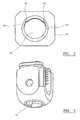
- FIG. 6 A perspective view of the clamp 16 as seen from the direction of the base of the clamp is depicted in Figure 6 .
- the base 18 of the clamp 16 comprises an edge which has an opening 20.
- the opening 20 is sized to enable the head 6 of the screw 2 to be inserted at a first orientation of the head 6 relative to the opening 20.
- the clamp 16 can then be rotated relative to the head 6 of the screw 2 in order to retain the screw 2 within the clamp 16.
- the perimeter of the opening 20 in this embodiment includes two protrusions 22.
- the protrusions 22 act to either allow the head 6 of the screw 2 to be inserted, or to retain the head 6 within the clamp 16, depending on the relative orientation of the head 6 to the clamp 16.
- the protrusions 22 each comprise a planar surface. This allows the head 6 to be inserted when the planar surfaces 8 are aligned with the planar surface of the protrusions 22. Once inserted into the clamp 16, the head of the clamp can then be rotated through 90°, whereupon the planar surfaces 8 of the head 6 are then located perpendicularly to the plane of the protrusions 22, and the protrusions 22 act to retain the head 6 within the clamp 16.
- the surface of the clamp 16 within the opening 20 includes an angled portion 24.
- the remainder of the internal surface of the clamp 16 extending from the opening 20 has a concave curve.
- This curved surface is indicated generally at 26 in Figure 6 .
- the concave curved surface 26 can engage the curved surface 10 on the head 6 of the screw 2.
- the clamp 16 can be seen to comprise a base 18 and two side members 28 extending generally perpendicularly to the base.
- the far end of the side members 28 comprises a series of grooves 30 which define a screw thread for receiving a set screw 21.
- Figure 4 also depicts an insert member 18.
- the insert member 18 is intended to restrict the movement of the screw 2 to pivoting within a single plane, which is angled with respect to a central axis of the opening 20.
- the insert member 18 includes two side members 32 extending downwardly, each having angled planar surfaces 34 opposite each other. The angle of the planar surfaces 34 determines the angle of the plane in which the screw 2 can pivot.
- An upper surface 36 of the insert member 18 is substantially planar and comprises a protrusion 38 at its centre.
- the protrusion 38 engages a corresponding recess in the shoulder member 20.
- the shoulder member 20 also comprises a corresponding planar surface to enable the insert member 18 to rotate relative to the shoulder member 20, rotating about the axis of the protrusion 38.
- This embodiment is intended for use with a support element having a generally octagonal cross-section.
- the shoulder member 20 therefore includes a surface 40 that is angled corresponding to the angles of the support element so that the support element is abutted on three sides by the shoulder member 20.
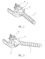
- FIG. 7 A partially cut-away perspective view of an assembly of the screw 2, clamp 16, insert member 18 and shoulder member 20 is depicted in Figure 7 in a first orientation and Figure 8 in a second orientation.
- Figure 7 depicts the orientation in which the screw can be inserted into the opening 20 in the base of the clamp16.
- the planar surfaces 8 of the screw are aligned with the planar surfaces 34 of the shoulder member 18 (not visible in Figure 7 ).
- the protrusion 38 can be seen engaging the recess in the shoulder member 20.
- the shoulder member 20 and the two side members 28 of the clamp 16 can be seen to define a channel for receiving the support element.
- Figure 8 depicts the assembly of Figure 7 in a second orientation in which the head 6 of the screw 2 is retained within the clamp 16.
- the clamp 16 and shoulder member 20 are rotated relative to the screw 4 and insert member 18.
- this relative movement has been depicted as a movement of the screw 16 and insert member 18.
- the relative position of the shoulder member 20 and the clamp 16 do not change.
- the screw 2 and the insert member 18 rotate within the clamp 16.
- the curved surface 10 of the screw 2 can engage a corresponding curved surface formed within the clamp 16.
- the components of this embodiment are preferably manufactured from titanium but any other bio-compatible material could also be used in alternate embodiments, including metals, metal alloys (for example stainless steel and colbalt chrome), polymers and composites.
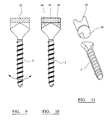
- Figure 9 depicts an alternative embodiment in which the screw 2 is also constrained to move within a single plane.
- the shoulder member 42 includes two planar surfaces which are not angled. This means that the screw is limited to pivoting in a plane which is parallel to the central axis of the opening, rather than angled with respect to the central axis of the opening.
- Figure 10 depicts an embodiment of an insert member 44 which prohibits movement of the screw relative to the insert member or clamp. It can be seen that the insert member 44 comprises two surfaces 46 that meet at an angle of less than 180°. The two surfaces engage the corresponding surfaces formed on the head of the screw 2 to grip the head of the screw 2 and prevent its movement relative to the insert member 44.
- FIG. 11 An additional alternate embodiment is depicted in Figure 11 .
- the screw 2 is configured to pivot about multiple planes relative to the central axis of the opening of the clamp.
- the insert member 48 takes a different form from the previous embodiment.
- the insert member 48 has a spherically convex surface and combines with the existing convex curved surface on the head of the screw 2 to define a substantially spherical surface. This spherical surface interacts with a corresponding concave spherical surface formed on the shoulder member 50.
- the shoulder member 50 could be a standard shoulder used with existing polyaxial screws as known to the person skilled in the art.
- the shoulder member 50 is intended for use with support elements having a circular cross-section and therefore includes a semi-circular recess on its upper surface.
- shoulder member and insert member may be combined into a single component.
- An example of such a combine shoulder and insert member is depicted in Figure 12 .
- the rotational connection between the shoulder member and the insert member can be configured to allow only limited rotation between the insert member and the shoulder member.
- Figure 13 depicts an example of the shoulder and insert members including a rotation stop. They are illustrated without the other parts of the assembly for clarity.
- An insert member 60 engages a shoulder member 62.
- a semi-circular protrusion 64 extends from a bearing surface 63 of the shoulder member 60.
- a corresponding recess 66 is formed in shoulder member 62.
- the recess 66 is in the form of a segment of a circle. In this embodiment the segment extends over an angle of 270°.
- Figures 13A and 13B illustrate the interaction between the protrusion 64 and the recess 66 that creates the rotational stop.
- the segment of the recess is 90° greater than the angle of 180° over which the semi-circular protrusion extends.
- the insert member can therefore be rotated by 90° relative to the shoulder member 62 to allow locking of the screw in the opening, between a first position depicted in Figure 13A and a second position depicted in Figure 13B .
- Alternative angular dimensions may be used in alternate embodiments.
- the bearing surfaces where relative rotation takes place can be provided with small protrusions, nodes or bumps which extend from each surface. These can act to increase friction between the components and also provide tactile feedback to a surgeon during relative movement of components. For example the components may "click" as they move past each other.
- the present invention may be used with support elements of any cross-sectional shape.
- the configuration of the head portion may also be varied from those specific examples given.
- the key feature of the head portion is a pair of planar surfaces joined by a curved surface.
- the opening of the base of the clamp may also be configured differently, depending on the specific way in which the head portion is configured, providing that the head portion can be inserted into the opening in a first orientation and locked in the opening in a second orientation.
- a single bone screw can be adapted to have varying degrees of freedom relative to a clamp depending on the requirements of the surgeon. This can vary between a full polyaxial screw that can pivot about several planes relative to an axis of an opening, a screw limited to pivoting in a single plane, or a screw which cannot move relative to the clamp.
- the configuration of the head of the screw also enables it to be inserted and removed from a clamp once the screw has been inserted into the bone, without needing to remove the screw from the bone. This simplifies the surgical procedure, as there is no need to negotiate the clamp while screwing in the screw and provides a benefit of easier revision.
- the screw and assembly of the present invention can be used in a method of surgery in which the screw is installed into the bone before being installed in the clamp.
- the installation of the screw into the clamp involves simply inserting the head of the screw at a first orientation and then rotating the screw relative to the clamp in order to lock it within the clamp. This avoids the application of axial forces to screw.
- the present invention also allows revision surgery where the clamp and insert member can be changed if necessary without requiring to remove the screw from the bone.
Landscapes
- Health & Medical Sciences (AREA)
- Orthopedic Medicine & Surgery (AREA)
- Life Sciences & Earth Sciences (AREA)
- Neurology (AREA)
- Surgery (AREA)
- Heart & Thoracic Surgery (AREA)
- Engineering & Computer Science (AREA)
- Biomedical Technology (AREA)
- Nuclear Medicine, Radiotherapy & Molecular Imaging (AREA)
- Medical Informatics (AREA)
- Molecular Biology (AREA)
- Animal Behavior & Ethology (AREA)
- General Health & Medical Sciences (AREA)
- Public Health (AREA)
- Veterinary Medicine (AREA)
- Surgical Instruments (AREA)
Applications Claiming Priority (1)
| Application Number | Priority Date | Filing Date | Title |
|---|---|---|---|
| GBGB0720762.4A GB0720762D0 (en) | 2007-10-24 | 2007-10-24 | Assembly for orthopaedic surgery |
Publications (1)
| Publication Number | Publication Date |
|---|---|
| EP2052690A1 true EP2052690A1 (fr) | 2009-04-29 |
Family
ID=38829776
Family Applications (1)
| Application Number | Title | Priority Date | Filing Date |
|---|---|---|---|
| EP08167244A Withdrawn EP2052690A1 (fr) | 2007-10-24 | 2008-10-22 | Ensemble pour chirurgie orthopédique |
Country Status (3)
| Country | Link |
|---|---|
| US (1) | US8430914B2 (fr) |
| EP (1) | EP2052690A1 (fr) |
| GB (1) | GB0720762D0 (fr) |
Cited By (13)
| Publication number | Priority date | Publication date | Assignee | Title |
|---|---|---|---|---|
| WO2012024665A3 (fr) * | 2010-08-20 | 2012-08-09 | K2M, Inc. | Système de fixation spinale |
| US8628558B2 (en) | 2008-11-03 | 2014-01-14 | DePuy Synthes Products, LLC | Uni-planer bone fixation assembly |
| AU2014200455B2 (en) * | 2010-08-20 | 2014-12-18 | K2M, Inc. | Spinal Fixation System |
| US9393049B2 (en) | 2010-08-20 | 2016-07-19 | K2M, Inc. | Spinal fixation system |
| US9393048B2 (en) | 2010-02-23 | 2016-07-19 | K2M, Inc. | Polyaxial bonescrew assembly |
| WO2016168163A1 (fr) * | 2015-04-13 | 2016-10-20 | Medos International Sarl | Ensembles d'ancrage osseux à indicateur d'orientation |
| US9848918B2 (en) | 2005-11-21 | 2017-12-26 | DePuy Synthes Products, Inc. | Polyaxial bone anchors with increased angulation |
| US9974571B2 (en) | 2008-09-12 | 2018-05-22 | DePuy Synthes Products, Inc. | Spinal stabilizing and guiding fixation system |
| US10105163B2 (en) | 2009-04-15 | 2018-10-23 | DePuy Synthes Products, Inc. | Revision connector for spinal constructs |
| US10136923B2 (en) | 2007-07-20 | 2018-11-27 | DePuy Synthes Products, Inc. | Polyaxial bone fixation element |
| US10154859B2 (en) | 2008-09-29 | 2018-12-18 | DePuy Synthes Products, Inc. | Polyaxial bottom-loading screw and rod assembly |
| US11006978B2 (en) | 2009-06-17 | 2021-05-18 | DePuy Synthes Products, Inc. | Revision connector for spinal constructs |
| US12611234B2 (en) | 2023-05-03 | 2026-04-28 | Vb Spine Us Opco Llc | Spinal fixation system |
Families Citing this family (121)
| Publication number | Priority date | Publication date | Assignee | Title |
|---|---|---|---|---|
| US7833250B2 (en) | 2004-11-10 | 2010-11-16 | Jackson Roger P | Polyaxial bone screw with helically wound capture connection |
| US10258382B2 (en) | 2007-01-18 | 2019-04-16 | Roger P. Jackson | Rod-cord dynamic connection assemblies with slidable bone anchor attachment members along the cord |
| US20160242816A9 (en) | 2001-05-09 | 2016-08-25 | Roger P. Jackson | Dynamic spinal stabilization assembly with elastic bumpers and locking limited travel closure mechanisms |
| US7862587B2 (en) | 2004-02-27 | 2011-01-04 | Jackson Roger P | Dynamic stabilization assemblies, tool set and method |
| US10729469B2 (en) | 2006-01-09 | 2020-08-04 | Roger P. Jackson | Flexible spinal stabilization assembly with spacer having off-axis core member |
| US8876868B2 (en) | 2002-09-06 | 2014-11-04 | Roger P. Jackson | Helical guide and advancement flange with radially loaded lip |
| US7621918B2 (en) | 2004-11-23 | 2009-11-24 | Jackson Roger P | Spinal fixation tool set and method |
| US7377923B2 (en) | 2003-05-22 | 2008-05-27 | Alphatec Spine, Inc. | Variable angle spinal screw assembly |
| US7776067B2 (en) | 2005-05-27 | 2010-08-17 | Jackson Roger P | Polyaxial bone screw with shank articulation pressure insert and method |
| US8814911B2 (en) | 2003-06-18 | 2014-08-26 | Roger P. Jackson | Polyaxial bone screw with cam connection and lock and release insert |
| US8936623B2 (en) | 2003-06-18 | 2015-01-20 | Roger P. Jackson | Polyaxial bone screw assembly |
| US8137386B2 (en) | 2003-08-28 | 2012-03-20 | Jackson Roger P | Polyaxial bone screw apparatus |
| US8377102B2 (en) | 2003-06-18 | 2013-02-19 | Roger P. Jackson | Polyaxial bone anchor with spline capture connection and lower pressure insert |
| US8398682B2 (en) | 2003-06-18 | 2013-03-19 | Roger P. Jackson | Polyaxial bone screw assembly |
| US7766915B2 (en) | 2004-02-27 | 2010-08-03 | Jackson Roger P | Dynamic fixation assemblies with inner core and outer coil-like member |
| US7179261B2 (en) | 2003-12-16 | 2007-02-20 | Depuy Spine, Inc. | Percutaneous access devices and bone anchor assemblies |
| US11419642B2 (en) | 2003-12-16 | 2022-08-23 | Medos International Sarl | Percutaneous access devices and bone anchor assemblies |
| US7527638B2 (en) | 2003-12-16 | 2009-05-05 | Depuy Spine, Inc. | Methods and devices for minimally invasive spinal fixation element placement |
| US8152810B2 (en) | 2004-11-23 | 2012-04-10 | Jackson Roger P | Spinal fixation tool set and method |
| US11241261B2 (en) | 2005-09-30 | 2022-02-08 | Roger P Jackson | Apparatus and method for soft spinal stabilization using a tensionable cord and releasable end structure |
| US7160300B2 (en) | 2004-02-27 | 2007-01-09 | Jackson Roger P | Orthopedic implant rod reduction tool set and method |
| AU2004317551B2 (en) | 2004-02-27 | 2008-12-04 | Roger P. Jackson | Orthopedic implant rod reduction tool set and method |
| US7503924B2 (en) | 2004-04-08 | 2009-03-17 | Globus Medical, Inc. | Polyaxial screw |
| US8475495B2 (en) | 2004-04-08 | 2013-07-02 | Globus Medical | Polyaxial screw |
| JP2008519656A (ja) | 2004-11-10 | 2008-06-12 | ロジャー・ピー・ジャクソン | 破断伸張部付の螺旋状案内及び前進フランジ |
| US8926672B2 (en) | 2004-11-10 | 2015-01-06 | Roger P. Jackson | Splay control closure for open bone anchor |
| US9393047B2 (en) | 2009-06-15 | 2016-07-19 | Roger P. Jackson | Polyaxial bone anchor with pop-on shank and friction fit retainer with low profile edge lock |
| US8444681B2 (en) | 2009-06-15 | 2013-05-21 | Roger P. Jackson | Polyaxial bone anchor with pop-on shank, friction fit retainer and winged insert |
| WO2006057837A1 (fr) * | 2004-11-23 | 2006-06-01 | Jackson Roger P | Structure d'accrochage pour outil de fixation spinale |
| US9168069B2 (en) | 2009-06-15 | 2015-10-27 | Roger P. Jackson | Polyaxial bone anchor with pop-on shank and winged insert with lower skirt for engaging a friction fit retainer |
| US8308782B2 (en) | 2004-11-23 | 2012-11-13 | Jackson Roger P | Bone anchors with longitudinal connecting member engaging inserts and closures for fixation and optional angulation |
| US9980753B2 (en) | 2009-06-15 | 2018-05-29 | Roger P Jackson | pivotal anchor with snap-in-place insert having rotation blocking extensions |
| US10076361B2 (en) | 2005-02-22 | 2018-09-18 | Roger P. Jackson | Polyaxial bone screw with spherical capture, compression and alignment and retention structures |
| US7901437B2 (en) | 2007-01-26 | 2011-03-08 | Jackson Roger P | Dynamic stabilization member with molded connection |
| GB0521582D0 (en) | 2005-10-22 | 2005-11-30 | Depuy Int Ltd | An implant for supporting a spinal column |
| GB0600662D0 (en) | 2006-01-13 | 2006-02-22 | Depuy Int Ltd | Spinal support rod kit |
| US8348952B2 (en) | 2006-01-26 | 2013-01-08 | Depuy International Ltd. | System and method for cooling a spinal correction device comprising a shape memory material for corrective spinal surgery |
| AU2007332794C1 (en) | 2006-12-08 | 2012-01-12 | Roger P. Jackson | Tool system for dynamic spinal implants |
| US11224463B2 (en) | 2007-01-18 | 2022-01-18 | Roger P. Jackson | Dynamic stabilization connecting member with pre-tensioned flexible core member |
| US8475498B2 (en) | 2007-01-18 | 2013-07-02 | Roger P. Jackson | Dynamic stabilization connecting member with cord connection |
| US10383660B2 (en) | 2007-05-01 | 2019-08-20 | Roger P. Jackson | Soft stabilization assemblies with pretensioned cords |
| CN102512229B (zh) * | 2007-07-20 | 2016-01-20 | 新特斯有限责任公司 | 多轴骨固定元件 |
| CN101909536B (zh) | 2007-10-24 | 2012-09-05 | 纽瓦西弗公司 | 外科固定系统 |
| GB0720762D0 (en) | 2007-10-24 | 2007-12-05 | Depuy Spine Sorl | Assembly for orthopaedic surgery |
| US8740956B2 (en) | 2008-01-10 | 2014-06-03 | J. Scott Smith | Pedicle screw |
| US8986318B2 (en) | 2008-06-03 | 2015-03-24 | Jeffrey Scott Smith | Pedicle depth measuring apparatus |
| US9668775B2 (en) | 2008-06-03 | 2017-06-06 | Jeffrey Scott Smith | Pedicle screw |
| US8007522B2 (en) | 2008-02-04 | 2011-08-30 | Depuy Spine, Inc. | Methods for correction of spinal deformities |
| US9060813B1 (en) | 2008-02-29 | 2015-06-23 | Nuvasive, Inc. | Surgical fixation system and related methods |
| JP2012529969A (ja) | 2008-08-01 | 2012-11-29 | ロジャー・ピー・ジャクソン | スリーブ付き張力付与りコードを備える長手方向接続部材 |
| WO2010028287A2 (fr) | 2008-09-05 | 2010-03-11 | Synthes Usa, Llc | Ensemble fixation osseuse |
| EP2174608B1 (fr) * | 2008-10-08 | 2012-08-01 | Biedermann Technologies GmbH & Co. KG | Dispositif d'ancrage osseux et dispositif de stabilisation pour les éléments osseux ou vertèbres |
| US8382805B2 (en) * | 2009-06-02 | 2013-02-26 | Alphatec Spine, Inc. | Bone screw assembly for limited angulation |
| US11464549B2 (en) | 2009-06-15 | 2022-10-11 | Roger P. Jackson | Pivotal bone anchor assembly with horizontal tool engagement grooves and insert with upright arms having flared outer portions |
| WO2013043218A1 (fr) | 2009-06-15 | 2013-03-28 | Jackson Roger P | Dispositif d'ancrage osseux polyaxial doté d'une tige à enclenchement par pression et insert à ailettes à pince de compression à ajustement par friction |
| US9668771B2 (en) | 2009-06-15 | 2017-06-06 | Roger P Jackson | Soft stabilization assemblies with off-set connector |
| US11229457B2 (en) | 2009-06-15 | 2022-01-25 | Roger P. Jackson | Pivotal bone anchor assembly with insert tool deployment |
| US8998959B2 (en) | 2009-06-15 | 2015-04-07 | Roger P Jackson | Polyaxial bone anchors with pop-on shank, fully constrained friction fit retainer and lock and release insert |
| US8568456B2 (en) * | 2009-09-21 | 2013-10-29 | Globus Medical, Inc. | Transverse connector having a locking element for capturing multiple rods |
| WO2011043805A1 (fr) | 2009-10-05 | 2011-04-14 | Roger Jackson P | Ancrage osseux polyaxial avec élément de rétention non rotatif et tige fixée par pression, et ajustement par frottement |
| US8298275B2 (en) * | 2009-10-30 | 2012-10-30 | Warsaw Orthopedic, Inc. | Direct control spinal implant |
| US8986349B1 (en) * | 2009-11-11 | 2015-03-24 | Nuvasive, Inc. | Systems and methods for correcting spinal deformities |
| US8419778B2 (en) | 2010-01-15 | 2013-04-16 | Ebi, Llc | Uniplanar bone anchor system |
| US8647370B2 (en) | 2010-01-15 | 2014-02-11 | Ebi, Llc | Uniplanar bone anchor system |
| US20110196430A1 (en) * | 2010-02-10 | 2011-08-11 | Walsh David A | Spinal fixation assembly with intermediate element |
| FR2958531B1 (fr) * | 2010-04-07 | 2012-08-31 | Michel Timoteo | Dispositif d'indexation par pivot et rainure de la poly axialite d'une vis pediculaire |
| US12383311B2 (en) | 2010-05-14 | 2025-08-12 | Roger P. Jackson | Pivotal bone anchor assembly and method for use thereof |
| US8641717B2 (en) | 2010-07-01 | 2014-02-04 | DePuy Synthes Products, LLC | Guidewire insertion methods and devices |
| US8777996B2 (en) | 2010-07-12 | 2014-07-15 | Globus Medical, Inc. | Interspinous ligament transverse connector |
| WO2012033532A1 (fr) | 2010-09-08 | 2012-03-15 | Roger Jackson P | Membres de stabilisation dynamiques dotés de sections élastiques et non élastiques |
| JP2013545527A (ja) | 2010-11-02 | 2013-12-26 | ロジャー・ピー・ジャクソン | ポップオン式シャンクと枢動可能な保持部とを有する多軸の骨アンカー |
| EP2462889B1 (fr) * | 2010-12-13 | 2013-08-21 | Biedermann Technologies GmbH & Co. KG | Dispositif d'ancrage d'os |
| US9387013B1 (en) | 2011-03-01 | 2016-07-12 | Nuvasive, Inc. | Posterior cervical fixation system |
| WO2012128825A1 (fr) | 2011-03-24 | 2012-09-27 | Jackson Roger P | Ancrage osseux polyaxial avec articulation composée et tige enclipsable |
| US8845693B2 (en) | 2011-04-27 | 2014-09-30 | Jeffrey Scott Smith | Tulip head apparatus |
| US11103286B2 (en) * | 2011-07-15 | 2021-08-31 | Globus Medical, Inc. | Orthopedic fixation devices and methods of installation thereof |
| US8888827B2 (en) | 2011-07-15 | 2014-11-18 | Globus Medical, Inc. | Orthopedic fixation devices and methods of installation thereof |
| US9186187B2 (en) | 2011-07-15 | 2015-11-17 | Globus Medical, Inc. | Orthopedic fixation devices and methods of installation thereof |
| US9198694B2 (en) | 2011-07-15 | 2015-12-01 | Globus Medical, Inc. | Orthopedic fixation devices and methods of installation thereof |
| US9993269B2 (en) | 2011-07-15 | 2018-06-12 | Globus Medical, Inc. | Orthopedic fixation devices and methods of installation thereof |
| US9358047B2 (en) | 2011-07-15 | 2016-06-07 | Globus Medical, Inc. | Orthopedic fixation devices and methods of installation thereof |
| US9295501B2 (en) | 2011-08-02 | 2016-03-29 | Blackstone Medical, Inc. | Bayonet counter-torque wrench |
| US9060818B2 (en) * | 2011-09-01 | 2015-06-23 | DePuy Synthes Products, Inc. | Bone implants |
| ES2546157T3 (es) | 2011-10-27 | 2015-09-21 | Biedermann Technologies Gmbh & Co. Kg | Dispositivo de anclaje óseo poliaxial de gran angulación |
| ES2570782T3 (es) * | 2011-12-23 | 2016-05-20 | Biedermann Technologies Gmbh | Dispositivo de anclaje de hueso poliaxial |
| WO2013106217A1 (fr) | 2012-01-10 | 2013-07-18 | Jackson, Roger, P. | Fermetures à départs multiples pour implants ouverts |
| US9782204B2 (en) | 2012-09-28 | 2017-10-10 | Medos International Sarl | Bone anchor assemblies |
| US8911478B2 (en) | 2012-11-21 | 2014-12-16 | Roger P. Jackson | Splay control closure for open bone anchor |
| US10058354B2 (en) | 2013-01-28 | 2018-08-28 | Roger P. Jackson | Pivotal bone anchor assembly with frictional shank head seating surfaces |
| US8852239B2 (en) | 2013-02-15 | 2014-10-07 | Roger P Jackson | Sagittal angle screw with integral shank and receiver |
| US20140277159A1 (en) * | 2013-03-14 | 2014-09-18 | DePuy Synthes Products, LLC | Bottom-loading bone anchor assemblies |
| US9775660B2 (en) | 2013-03-14 | 2017-10-03 | DePuy Synthes Products, Inc. | Bottom-loading bone anchor assemblies and methods |
| US20140277153A1 (en) | 2013-03-14 | 2014-09-18 | DePuy Synthes Products, LLC | Bone Anchor Assemblies and Methods With Improved Locking |
| US9724145B2 (en) | 2013-03-14 | 2017-08-08 | Medos International Sarl | Bone anchor assemblies with multiple component bottom loading bone anchors |
| US10342582B2 (en) | 2013-03-14 | 2019-07-09 | DePuy Synthes Products, Inc. | Bone anchor assemblies and methods with improved locking |
| US9259247B2 (en) | 2013-03-14 | 2016-02-16 | Medos International Sarl | Locking compression members for use with bone anchor assemblies and methods |
| US9433445B2 (en) | 2013-03-14 | 2016-09-06 | DePuy Synthes Products, Inc. | Bone anchors and surgical instruments with integrated guide tips |
| US9526529B2 (en) | 2013-09-25 | 2016-12-27 | Blackstone Medical, Inc. | Bone screw systems with pressure caps having biasing members |
| US9480501B2 (en) * | 2013-10-21 | 2016-11-01 | Blackstone Medical, Inc. | Modular pedicle screw |
| US9566092B2 (en) | 2013-10-29 | 2017-02-14 | Roger P. Jackson | Cervical bone anchor with collet retainer and outer locking sleeve |
| US9980758B2 (en) | 2013-11-27 | 2018-05-29 | Blackstone Medical, Inc. | Minimally invasive counter-torque wrench system |
| US9717533B2 (en) | 2013-12-12 | 2017-08-01 | Roger P. Jackson | Bone anchor closure pivot-splay control flange form guide and advancement structure |
| US9451993B2 (en) | 2014-01-09 | 2016-09-27 | Roger P. Jackson | Bi-radial pop-on cervical bone anchor |
| US10918419B2 (en) * | 2014-04-01 | 2021-02-16 | K2M, Inc. | Spinal fixation device |
| US9549765B2 (en) | 2014-04-03 | 2017-01-24 | Zimmer Spine, Inc. | Uniplanar bone screw |
| US9597119B2 (en) | 2014-06-04 | 2017-03-21 | Roger P. Jackson | Polyaxial bone anchor with polymer sleeve |
| US10064658B2 (en) | 2014-06-04 | 2018-09-04 | Roger P. Jackson | Polyaxial bone anchor with insert guides |
| US9737340B1 (en) * | 2014-09-16 | 2017-08-22 | Nuvasive, Inc. | Adjustable iliac connector |
| US9924975B2 (en) | 2014-10-21 | 2018-03-27 | Roger P. Jackson | Bone anchor having a snap-fit assembly |
| US10543021B2 (en) | 2014-10-21 | 2020-01-28 | Roger P. Jackson | Pivotal bone anchor assembly having an open ring positioner for a retainer |
| US10149702B2 (en) | 2015-01-12 | 2018-12-11 | Imds Llc | Polyaxial screw and rod system |
| US9968378B1 (en) * | 2015-07-22 | 2018-05-15 | University Of South Florida | Adaptation sphere saddle |
| US9974569B2 (en) * | 2015-08-10 | 2018-05-22 | Warsaw Orthopedic, Inc. | Spinal implant system and methods of use |
| US10130395B2 (en) * | 2015-08-17 | 2018-11-20 | Globus Medical, Inc. | Modular uniplanar pedicle screw assembly for use with a polyaxial bone fastener |
| US10022157B2 (en) * | 2015-11-20 | 2018-07-17 | Blackstone Medical, Inc. | Convertible screw for spinal fixation |
| US10034691B1 (en) | 2015-12-03 | 2018-07-31 | Nuvasive, Inc. | Bone anchor |
| WO2017127647A1 (fr) * | 2016-01-22 | 2017-07-27 | Spinal Usa, Inc. | Systèmes et procédés de fixation vertébrale |
| US10575878B2 (en) * | 2016-07-21 | 2020-03-03 | Warsaw Orthopedic, Inc. | Spinal implant system and methods of use |
| CA3043217A1 (fr) | 2016-11-18 | 2018-05-24 | Javier Garcia-Bengochea | Implants et instruments pour ameliorer l'alignement vertebral et l'equilibre sagittal |
| WO2022184797A1 (fr) | 2021-03-05 | 2022-09-09 | Medos International Sarl | Vis polyaxiale à verrouillage sélectif |
| CN115670621B (zh) * | 2022-10-26 | 2026-03-24 | 浙江德康医疗器械有限公司 | 一种仿生微动可调结构的椎弓根螺钉 |
Citations (10)
| Publication number | Priority date | Publication date | Assignee | Title |
|---|---|---|---|---|
| US20030023240A1 (en) | 1997-01-22 | 2003-01-30 | Synthes (Usa) | Device for connecting a longitudinal bar to a pedicle screw |
| US6716214B1 (en) | 2003-06-18 | 2004-04-06 | Roger P. Jackson | Polyaxial bone screw with spline capture connection |
| WO2004041100A1 (fr) | 2002-10-30 | 2004-05-21 | Spinal Concepts, Inc. | Insertion de systeme de stabilisation rachidien et procedes |
| WO2004103194A1 (fr) * | 2003-05-22 | 2004-12-02 | Alphatec Manufacturing, Inc. | Ensemble vis vertebrale a angle variable |
| US20060111715A1 (en) * | 2004-02-27 | 2006-05-25 | Jackson Roger P | Dynamic stabilization assemblies, tool set and method |
| US20060155277A1 (en) | 2002-03-21 | 2006-07-13 | Peter Metz-Stavenhagen | Anchoring element for securing a rod of a device for adjusting a human or animal vertrebal column on a vertreba |
| US20060200131A1 (en) * | 2005-03-04 | 2006-09-07 | Depuy Spine Sarl | Constrained motion bone screw assembly |
| US20060235389A1 (en) * | 2005-03-03 | 2006-10-19 | Accin Corporation | Spinal stabilization using bone anchor and anchor seat with tangential locking feature |
| EP1774919A1 (fr) | 2005-10-12 | 2007-04-18 | BIEDERMANN MOTECH GmbH | Vis polyaxiale pivotable dans un seul plan |
| WO2007047711A2 (fr) * | 2005-10-20 | 2007-04-26 | Warsaw Orthopedic, Inc. | Ensemble de vis multiaxial a chargement par le bas |
Family Cites Families (333)
| Publication number | Priority date | Publication date | Assignee | Title |
|---|---|---|---|---|
| US2669896A (en) | 1951-01-19 | 1954-02-23 | Robert S Clough | Retractable jaw wrench having parallel resilient jaws |
| US2952285A (en) | 1958-12-09 | 1960-09-13 | Gramiger A G Geb | Screwdrivers |
| US3604487A (en) | 1969-03-10 | 1971-09-14 | Richard S Gilbert | Orthopedic screw driving means |
| NL7202840A (fr) | 1972-03-03 | 1973-09-06 | ||
| US3786806A (en) | 1972-11-22 | 1974-01-22 | A Johnson | Thermoconstrictive surgical appliance |
| US4289123A (en) | 1980-03-31 | 1981-09-15 | Dunn Harold K | Orthopedic appliance |
| JPS56147085U (fr) | 1980-04-04 | 1981-11-05 | ||
| US5190546A (en) | 1983-10-14 | 1993-03-02 | Raychem Corporation | Medical devices incorporating SIM alloy elements |
| FR2553993B1 (fr) | 1983-10-28 | 1986-02-07 | Peze William | Procede et appareil de correction dynamique des deformations rachidiennes |
| US4611582A (en) | 1983-12-27 | 1986-09-16 | Wisconsin Alumni Research Foundation | Vertebral clamp |
| DE3414374C2 (de) | 1984-04-16 | 1986-12-18 | Patrick Dr. 3590 Bad Wildungen Kluger | Vorrichtung zum Einrichten einer Wirbelsäule mit geschädigten Wirbelkörpern |
| US4592933A (en) | 1984-06-29 | 1986-06-03 | International Business Machines Corporation | High efficiency homogeneous chemical vapor deposition |
| US4743260A (en) | 1985-06-10 | 1988-05-10 | Burton Charles V | Method for a flexible stabilization system for a vertebral column |
| DE3711091A1 (de) | 1987-04-02 | 1988-10-13 | Kluger Patrick | Vorrichtung zum einrichten einer wirbelsaeule mit geschaedigten wirbelkoerpern |
| DE3800052A1 (de) | 1987-07-08 | 1989-07-13 | Harms Juergen | Positionierungsschraube |
| FR2624720B1 (fr) | 1987-12-21 | 1994-04-15 | Fabrication Materiel Orthopediqu | Implant pour dispositif d'osteosynthese, notamment du rachis |
| US5468241A (en) | 1988-02-18 | 1995-11-21 | Howmedica Gmbh | Support device for the human vertebral column |
| US4887596A (en) | 1988-03-02 | 1989-12-19 | Synthes (U.S.A.) | Open backed pedicle screw |
| FR2633177B1 (fr) | 1988-06-24 | 1991-03-08 | Fabrication Materiel Orthopedi | Implant pour dispositif d'osteosynthese rachidienne, notamment en traumatologie |
| FR2642645B1 (fr) | 1989-02-03 | 1992-08-14 | Breard Francis | Stabilisateur intervertebral souple ainsi que procede et appareillage pour le controle de sa tension avant mise en place sur le rachis |
| FR2642643B1 (fr) | 1989-02-09 | 1991-05-10 | Vignaud Jean Louis | Instrumentation rachidienne pour fixation pediculaire universelle par vis diapason a reglage micrometrique |
| US4987892A (en) | 1989-04-04 | 1991-01-29 | Krag Martin H | Spinal fixation device |
| FR2645732B1 (fr) | 1989-04-13 | 1997-01-03 | Cotrel Yves | Implant vertebral pour dispositif d'osteosynthese |
| DE3923996A1 (de) | 1989-07-20 | 1991-01-31 | Lutz Biedermann | Aufnahmeteil zum gelenkigen verbinden mit einer schraube zum bilden einer pedikelschraube |
| JP3158405B2 (ja) | 1989-07-21 | 2001-04-23 | ブラザー工業株式会社 | フアクシミリ装置の通信管理情報処理装置 |
| CA2035348C (fr) | 1990-02-08 | 2000-05-16 | Jean-Louis Vignaud | Dispositif de fixation orientable de tiges d'osteosynthese rachidienne |
| FR2659225B1 (fr) | 1990-03-08 | 1995-09-08 | Sofamor | Dispositif de fixation transverse pour assurer une liaison transversale rigide entre deux tiges d'un systeme d'osteosynthese rachidienne. |
| US5360431A (en) | 1990-04-26 | 1994-11-01 | Cross Medical Products | Transpedicular screw system and method of use |
| US5290289A (en) | 1990-05-22 | 1994-03-01 | Sanders Albert E | Nitinol spinal instrumentation and method for surgically treating scoliosis |
| US5540689A (en) | 1990-05-22 | 1996-07-30 | Sanders; Albert E. | Apparatus for securing a rod adjacent to a bone |
| US5102412A (en) | 1990-06-19 | 1992-04-07 | Chaim Rogozinski | System for instrumentation of the spine in the treatment of spinal deformities |
| US5120171A (en) | 1990-11-27 | 1992-06-09 | Stuart Surgical | Bone screw with improved threads |
| US5417533A (en) | 1990-07-13 | 1995-05-23 | National Medical Specialty, Inc. | Bone screw with improved threads |
| US5129900B1 (en) | 1990-07-24 | 1998-12-29 | Acromed Corp | Spinal column retaining method and apparatus |
| US5133716A (en) | 1990-11-07 | 1992-07-28 | Codespi Corporation | Device for correction of spinal deformities |
| CH685850A5 (de) | 1990-11-26 | 1995-10-31 | Synthes Ag | Verankerungseinrichtung |
| FR2672202B1 (fr) | 1991-02-05 | 1993-07-30 | Safir | Implant chirurgical osseux, notamment pour stabilisateur inter-vertebral. |
| US5219349A (en) | 1991-02-15 | 1993-06-15 | Howmedica, Inc. | Spinal fixator reduction frame |
| DE4107480C2 (de) | 1991-03-08 | 1994-09-22 | Heinrich Ulrich | Pedikelschraube für Implantate zur Korrektur und Stabilisierung der Wirbelsäule |
| US5176678A (en) | 1991-03-14 | 1993-01-05 | Tsou Paul M | Orthopaedic device with angularly adjustable anchor attachments to the vertebrae |
| FR2676911B1 (fr) | 1991-05-30 | 1998-03-06 | Psi Ste Civile Particuliere | Dispositif de stabilisation intervertebrale a amortisseurs. |
| GB9122753D0 (en) | 1991-10-26 | 1991-12-11 | Reis Nicolas D | Internal ilio-lumbar fixator |
| DE9202745U1 (de) | 1992-03-02 | 1992-04-30 | Howmedica Gmbh, 2314 Schoenkirchen | Vorrichtung zum Verspannen von Wirbeln der menschlichen Wirbelsäule |
| NL9200612A (nl) | 1992-04-01 | 1993-11-01 | Acromed Bv | Inrichting ter correctie van de vorm en/of ter fixatie van de wervelkolom van de mens. |
| DE59301618D1 (de) | 1992-06-04 | 1996-03-28 | Synthes Ag | Osteosynthetisches Befestigungselement |
| DE59208301D1 (de) | 1992-06-25 | 1997-05-07 | Synthes Ag | Osteosynthetische fixationsvorrichtung |
| US5545165A (en) | 1992-10-09 | 1996-08-13 | Biedermann Motech Gmbh | Anchoring member |
| US5281223A (en) | 1992-09-21 | 1994-01-25 | Ray R Charles | Tool and method for derotating scoliotic spine |
| EP0673230A1 (fr) | 1992-10-05 | 1995-09-27 | Albert E. Sanders | Instruments chirurgicaux en nitinol et procede pour traiter la scoliose |
| US5263939A (en) | 1992-10-09 | 1993-11-23 | Surgin Surgical Instrumentation, Inc. | Retainer for laparoscopic cannula |
| DE4243951C2 (de) | 1992-12-23 | 1997-07-03 | Plus Endoprothetik Ag | Vorrichtung zur Versteifung eines aus wenigstens zwei Wirbeln bestehenden Wirbelsäulenabschnitts |
| US5947965A (en) | 1992-12-31 | 1999-09-07 | Bryan; Donald W. | Spinal fixation apparatus and method |
| US5387212A (en) | 1993-01-26 | 1995-02-07 | Yuan; Hansen A. | Vertebral locking and retrieving system with central locking rod |
| US5437673A (en) | 1993-02-04 | 1995-08-01 | Cryomedical Sciences, Inc. | Closed circulation tissue warming apparatus and method of using the same in prostate surgery |
| US5413576A (en) | 1993-02-10 | 1995-05-09 | Rivard; Charles-Hilaire | Apparatus for treating spinal disorder |
| US5282801A (en) | 1993-02-17 | 1994-02-01 | Danek Medical, Inc. | Top tightening clamp assembly for a spinal fixation system |
| US5330473A (en) | 1993-03-04 | 1994-07-19 | Advanced Spine Fixation Systems, Inc. | Branch connector for spinal fixation systems |
| US5551871A (en) | 1993-03-05 | 1996-09-03 | Besselink; Petrus A. | Temperature-sensitive medical/dental apparatus |
| US5415661A (en) | 1993-03-24 | 1995-05-16 | University Of Miami | Implantable spinal assist device |
| US5487744A (en) | 1993-04-08 | 1996-01-30 | Advanced Spine Fixation Systems, Inc. | Closed connector for spinal fixation systems |
| DE4316542C1 (de) | 1993-05-18 | 1994-07-21 | Schaefer Micomed Gmbh | Osteosynthesevorrichtung |
| US6077262A (en) | 1993-06-04 | 2000-06-20 | Synthes (U.S.A.) | Posterior spinal implant |
| US5445140A (en) | 1993-06-07 | 1995-08-29 | United States Surgical Corporation | Endoscopic surgical device |
| US5437669A (en) | 1993-08-12 | 1995-08-01 | Amei Technologies Inc. | Spinal fixation systems with bifurcated connectors |
| FR2709246B1 (fr) | 1993-08-27 | 1995-09-29 | Martin Jean Raymond | Orthèse vertébrale implantée dynamique. |
| US5466238A (en) | 1993-08-27 | 1995-11-14 | Lin; Chih-I | Vertebral locking and retrieving system having a fixation crossbar |
| US5499983A (en) | 1994-02-23 | 1996-03-19 | Smith & Nephew Richards, Inc. | Variable angle spinal screw |
| US5601552A (en) | 1994-03-18 | 1997-02-11 | Sofamor, S.N.C. | Fixing device for a rigid transverse connection device between rods of a spinal osteosynthesis system |
| US5645520A (en) | 1994-10-12 | 1997-07-08 | Computer Motion, Inc. | Shape memory alloy actuated rod for endoscopic instruments |
| US5536127A (en) | 1994-10-13 | 1996-07-16 | Pennig; Dietmar | Headed screw construction for use in fixing the position of an intramedullary nail |
| US6176861B1 (en) | 1994-10-25 | 2001-01-23 | Sdgi Holdings, Inc. | Modular spinal system |
| US5593408A (en) | 1994-11-30 | 1997-01-14 | Sofamor S.N.C | Vertebral instrumentation rod |
| FR2729556B1 (fr) | 1995-01-23 | 1998-10-16 | Sofamor | Dispositif d'osteosynthese rachidienne a crochet median et appuis d'ancrage vertebral |
| US5961515A (en) | 1995-03-01 | 1999-10-05 | Smith & Nephew, Inc. | External skeletal fixation system |
| US5549552A (en) | 1995-03-02 | 1996-08-27 | Scimed Life Systems, Inc. | Balloon dilation catheter with improved pushability, trackability and crossability |
| DE19509332C1 (de) | 1995-03-15 | 1996-08-14 | Harms Juergen | Verankerungselement |
| US5591166A (en) | 1995-03-27 | 1997-01-07 | Smith & Nephew Richards, Inc. | Multi angle bone bolt |
| US5595843A (en) * | 1995-03-30 | 1997-01-21 | Intel Corporation | Layout methodology, mask set, and patterning method for phase-shifting lithography |
| US5882350A (en) | 1995-04-13 | 1999-03-16 | Fastenetix, Llc | Polyaxial pedicle screw having a threaded and tapered compression locking mechanism |
| US5630816A (en) | 1995-05-01 | 1997-05-20 | Kambin; Parviz | Double barrel spinal fixation system and method |
| US5947966A (en) | 1995-06-06 | 1999-09-07 | Sdgi Holdings, Inc. | Device for linking adjacent rods in spinal instrumentation |
| US5667513A (en) | 1995-06-07 | 1997-09-16 | Smith & Nephew Dyonics Inc. | Soft tissue anchor delivery apparatus |
| US5833707A (en) | 1995-07-05 | 1998-11-10 | Advanced Cardiovascular Systems, Inc. | Removable stent and method of deployment |
| US5549608A (en) | 1995-07-13 | 1996-08-27 | Fastenetix, L.L.C. | Advanced polyaxial locking screw and coupling element device for use with rod fixation apparatus |
| FR2737222B1 (fr) | 1995-07-24 | 1997-10-17 | Transgene Sa | Nouveaux vecteurs viraux et lignee pour la therapie genique |
| US5643263A (en) | 1995-08-14 | 1997-07-01 | Simonson; Peter Melott | Spinal implant connection assembly |
| US6273914B1 (en) | 1995-09-28 | 2001-08-14 | Sparta, Inc. | Spinal implant |
| US5752955A (en) | 1995-10-30 | 1998-05-19 | Fastenetix, L.L.C. | Sliding shaft variable length cross-link device for use with dual rod apparatus |
| US5626581A (en) | 1995-11-27 | 1997-05-06 | Volunteers For Medical Engineering | Implantable bone lengthening apparatus |
| US6042605A (en) | 1995-12-14 | 2000-03-28 | Gore Enterprose Holdings, Inc. | Kink resistant stent-graft |
| US5649931A (en) | 1996-01-16 | 1997-07-22 | Zimmer, Inc. | Orthopaedic apparatus for driving and/or removing a bone screw |
| US5743807A (en) * | 1996-01-24 | 1998-04-28 | Tempo-Tuner Inc. | Golf swing sound training device |
| US5658286A (en) | 1996-02-05 | 1997-08-19 | Sava; Garard A. | Fabrication of implantable bone fixation elements |
| DE69631128T2 (de) | 1996-03-27 | 2004-09-23 | Lubos Rehak | Vorrichtung zur korrektur von verformungen der wirbelsäule |
| DE29606468U1 (de) | 1996-04-09 | 1997-08-07 | Waldemar Link GmbH & Co, 22339 Hamburg | Wirbelsäulenfixateur |
| US5830179A (en) | 1996-04-09 | 1998-11-03 | Endocare, Inc. | Urological stent therapy system and method |
| US5951493A (en) | 1997-05-16 | 1999-09-14 | Mercury Diagnostics, Inc. | Methods and apparatus for expressing body fluid from an incision |
| PT907858E (pt) | 1996-07-03 | 2004-02-27 | Codelast Ltd | Juntas |
| US5797911A (en) | 1996-09-24 | 1998-08-25 | Sdgi Holdings, Inc. | Multi-axial bone screw assembly |
| US5879350A (en) | 1996-09-24 | 1999-03-09 | Sdgi Holdings, Inc. | Multi-axial bone screw assembly |
| US5964760A (en) | 1996-10-18 | 1999-10-12 | Spinal Innovations | Spinal implant fixation assembly |
| US6171311B1 (en) | 1996-10-18 | 2001-01-09 | Marc Richelsoph | Transverse connector |
| JP2002514100A (ja) | 1996-10-24 | 2002-05-14 | スピナル コンセプツ,インク. | 脊椎を固定するための方法および装置 |
| US6310300B1 (en) | 1996-11-08 | 2001-10-30 | International Business Machines Corporation | Fluorine-free barrier layer between conductor and insulator for degradation prevention |
| FR2755844B1 (fr) | 1996-11-15 | 1999-01-29 | Stryker France Sa | Systeme d'osteosynthese a deformation elastique pour colonne vertebrale |
| AU732351B2 (en) | 1996-12-12 | 2001-04-26 | Synthes Gmbh | Device for the connection of a longitudinal support with a pedicle screw |
| US5782833A (en) | 1996-12-20 | 1998-07-21 | Haider; Thomas T. | Pedicle screw system for osteosynthesis |
| NL1004873C2 (nl) | 1996-12-23 | 1998-06-24 | Univ Twente | Inrichting voor het onderling verplaatsen van twee objecten. |
| FR2757761B1 (fr) | 1996-12-27 | 1999-08-20 | Stryker France Sa | Systeme d'oteosynthese du rachis avec reglage en position |
| US5910141A (en) | 1997-02-12 | 1999-06-08 | Sdgi Holdings, Inc. | Rod introduction apparatus |
| US5919158A (en) | 1997-02-13 | 1999-07-06 | Emory University | Method and apparatus for preventing and clearing condensation on the lens during a fluid-gas exchange portion of a pars plana vitrectomy |
| FR2759893B1 (fr) | 1997-02-26 | 1999-10-22 | Stryker France Sa | Bague pour dispositif d'osteosynthese a angulation, et dispositif d'osteosynthese l'incorporant |
| AU745916B2 (en) | 1997-03-07 | 2002-04-11 | Kyphon Sarl | Systems for percutaneous bone and spinal stabilization, fixation and repair |
| US5997580A (en) | 1997-03-27 | 1999-12-07 | Johnson & Johnson Professional, Inc. | Cement restrictor including shape memory material |
| US5989254A (en) | 1997-05-20 | 1999-11-23 | Katz; Akiva Raphael | Pedicle screw assembly |
| FR2763831B1 (fr) | 1997-05-29 | 1999-08-06 | Materiel Orthopedique En Abreg | Tige vertebrale de section constante pour instrumentations d'osteosynthese rachidienne |
| DE29710484U1 (de) | 1997-06-16 | 1998-10-15 | Howmedica GmbH, 24232 Schönkirchen | Aufnahmeteil für ein Haltebauteil eines Wirbelsäulenimplantats |
| US5902299A (en) | 1997-07-29 | 1999-05-11 | Jayaraman; Swaminathan | Cryotherapy method for reducing tissue injury after balloon angioplasty or stent implantation |
| US5964770A (en) | 1997-09-30 | 1999-10-12 | Litana Ltd. | High strength medical devices of shape memory alloy |
| FR2771280B1 (fr) | 1997-11-26 | 2001-01-26 | Albert P Alby | Dispositif de liaison vertebrale resilient |
| EP0933065A1 (fr) | 1998-02-02 | 1999-08-04 | Sulzer Orthopädie AG | Système de fixation articulé pour une vis à os |
| US6597279B1 (en) | 1998-03-06 | 2003-07-22 | Sony Corporation | Portable information terminal and method of setting the same |
| DE29806563U1 (de) | 1998-04-09 | 1998-06-18 | Howmedica GmbH, 24232 Schönkirchen | Pedikelschraube und Montagehilfe dafür |
| TW415228U (en) | 1998-04-29 | 2000-12-11 | Nat Science Council | Internal fixer for front position of the spine |
| US6447478B1 (en) | 1998-05-15 | 2002-09-10 | Ronald S. Maynard | Thin-film shape memory alloy actuators and processing methods |
| US7494488B2 (en) | 1998-05-28 | 2009-02-24 | Pearl Technology Holdings, Llc | Facial tissue strengthening and tightening device and methods |
| DE19829523A1 (de) | 1998-07-02 | 2000-01-05 | Michael Butsch | Distraktionsvorrichtung zum Auseinanderbewegen eines ein- oder zweiteiligen, ggf. getrennten Knochens |
| US6816968B1 (en) | 1998-07-10 | 2004-11-09 | Silverbrook Research Pty Ltd | Consumable authentication protocol and system |
| US6110172A (en) | 1998-07-31 | 2000-08-29 | Jackson; Roger P. | Closure system for open ended osteosynthesis apparatus |
| DE19835816C2 (de) | 1998-08-08 | 2002-02-07 | Schaefer Micomed Gmbh | Osteosynthesevorrichtung |
| TW355947U (en) | 1998-09-24 | 1999-04-11 | Yun Yen Co Ltd | Improved structure for hair drier with far infrared ray |
| US6358276B1 (en) | 1998-09-30 | 2002-03-19 | Impra, Inc. | Fluid containing endoluminal stent |
| US5910142A (en) | 1998-10-19 | 1999-06-08 | Bones Consulting, Llc | Polyaxial pedicle screw having a rod clamping split ferrule coupling element |
| FR2786088B1 (fr) | 1998-11-24 | 2001-04-06 | Dimso Sa | Dispositif d'osteosynthese rachidienne a bague de serrage |
| US6592577B2 (en) | 1999-01-25 | 2003-07-15 | Cryocath Technologies Inc. | Cooling system |
| US6050997A (en) | 1999-01-25 | 2000-04-18 | Mullane; Thomas S. | Spinal fixation system |
| KR100324698B1 (ko) | 1999-01-30 | 2002-02-27 | 구자교 | 척추고정장치 |
| FR2789886B1 (fr) | 1999-02-18 | 2001-07-06 | Dimso Sa | Dispositif de distraction/contraction pour systeme d'osteosynthese rachidienne |
| US6302888B1 (en) | 1999-03-19 | 2001-10-16 | Interpore Cross International | Locking dovetail and self-limiting set screw assembly for a spinal stabilization member |
| US6299613B1 (en) | 1999-04-23 | 2001-10-09 | Sdgi Holdings, Inc. | Method for the correction of spinal deformities through vertebral body tethering without fusion |
| US6325805B1 (en) | 1999-04-23 | 2001-12-04 | Sdgi Holdings, Inc. | Shape memory alloy staple |
| US6238491B1 (en) | 1999-05-05 | 2001-05-29 | Davitech, Inc. | Niobium-titanium-zirconium-molybdenum (nbtizrmo) alloys for dental and other medical device applications |
| US6254602B1 (en) | 1999-05-28 | 2001-07-03 | Sdgi Holdings, Inc. | Advanced coupling device using shape-memory technology |
| ES2154227B1 (es) | 1999-06-30 | 2001-11-16 | Surgival Co S A | Sistema poliaxial de fijacion de vertebras. |
| US6465183B2 (en) * | 1999-07-01 | 2002-10-15 | Agilent Technologies, Inc. | Multidentate arrays |
| US6280442B1 (en) | 1999-09-01 | 2001-08-28 | Sdgi Holdings, Inc. | Multi-axial bone screw assembly |
| AU1493301A (en) | 1999-09-27 | 2001-04-30 | Blackstone Medical, Inc. | A surgical screw system and related methods |
| US6554834B1 (en) | 1999-10-07 | 2003-04-29 | Stryker Spine | Slotted head pedicle screw assembly |
| US6530929B1 (en) | 1999-10-20 | 2003-03-11 | Sdgi Holdings, Inc. | Instruments for stabilization of bony structures |
| US20050261770A1 (en) | 2004-04-22 | 2005-11-24 | Kuiper Mark K | Crossbar spinal prosthesis having a modular design and related implantation methods |
| US7691145B2 (en) | 1999-10-22 | 2010-04-06 | Facet Solutions, Inc. | Prostheses, systems and methods for replacement of natural facet joints with artificial facet joint surfaces |
| US8187303B2 (en) | 2004-04-22 | 2012-05-29 | Gmedelaware 2 Llc | Anti-rotation fixation element for spinal prostheses |
| EP1227085B1 (fr) | 1999-10-22 | 2006-03-15 | Takeda Pharmaceutical Company Limited | Procede de production de derive de naphtalene optiquement actif et son separateur optique |
| DE10005386A1 (de) | 2000-02-07 | 2001-08-09 | Ulrich Gmbh & Co Kg | Pedikelschraube |
| DE10005385A1 (de) | 2000-02-07 | 2001-08-09 | Ulrich Gmbh & Co Kg | Pedikelschraube |
| US6443953B1 (en) | 2000-02-08 | 2002-09-03 | Cross Medical Products, Inc. | Self-aligning cap nut for use with a spinal rod anchor |
| US6261288B1 (en) | 2000-02-08 | 2001-07-17 | Roger P. Jackson | Implant stabilization and locking system |
| US6235028B1 (en) | 2000-02-14 | 2001-05-22 | Sdgi Holdings, Inc. | Surgical guide rod |
| US6423065B2 (en) | 2000-02-25 | 2002-07-23 | Bret A. Ferree | Cross-coupled vertebral stabilizers including cam-operated cable connectors |
| US20020133155A1 (en) | 2000-02-25 | 2002-09-19 | Ferree Bret A. | Cross-coupled vertebral stabilizers incorporating spinal motion restriction |
| US6293949B1 (en) | 2000-03-01 | 2001-09-25 | Sdgi Holdings, Inc. | Superelastic spinal stabilization system and method |
| US7322979B2 (en) | 2000-03-15 | 2008-01-29 | Warsaw Orthopedic, Inc. | Multidirectional pivoting bone screw and fixation system |
| US6309391B1 (en) | 2000-03-15 | 2001-10-30 | Sdgi Holding, Inc. | Multidirectional pivoting bone screw and fixation system |
| US6440137B1 (en) | 2000-04-18 | 2002-08-27 | Andres A. Horvath | Medical fastener cap system |
| JP3521253B2 (ja) | 2000-05-18 | 2004-04-19 | 株式会社東北テクノアーチ | 生体用形状記憶合金 |
| US6616668B2 (en) | 2000-06-09 | 2003-09-09 | Cross Medical Products, Inc. | Adjustable transverse connector for use with a spinal implant system |
| US6471716B1 (en) | 2000-07-11 | 2002-10-29 | Joseph P. Pecukonis | Low level light therapy method and apparatus with improved wavelength, temperature and voltage control |
| FR2812186B1 (fr) | 2000-07-25 | 2003-02-28 | Spine Next Sa | Piece de liaison souple pour la stabilisation du rachis |
| FR2812185B1 (fr) | 2000-07-25 | 2003-02-28 | Spine Next Sa | Piece de liaison semi-rigide pour la stabilisation du rachis |
| FR2813782B1 (fr) | 2000-09-13 | 2003-07-18 | Eurosurgical | Ancillaire pour la correction d'un segment rachidien et la mise en place d'un dispositif d'osteosynthese rachidienne reliant chaque vertebre du segment rachidien a corriger |
| US6485491B1 (en) | 2000-09-15 | 2002-11-26 | Sdgi Holdings, Inc. | Posterior fixation system |
| ATE296580T1 (de) | 2000-09-18 | 2005-06-15 | Zimmer Gmbh | Pedikelschraube für intervertebrale stützelemente |
| US6755829B1 (en) | 2000-09-22 | 2004-06-29 | Depuy Acromed, Inc. | Lock cap anchor assembly for orthopaedic fixation |
| US6296607B1 (en) | 2000-10-20 | 2001-10-02 | Praxis, Llc. | In situ bulking device |
| US6743231B1 (en) | 2000-10-02 | 2004-06-01 | Sulzer Spine-Tech Inc. | Temporary spinal fixation apparatuses and methods |
| US6887241B1 (en) | 2000-10-06 | 2005-05-03 | Spinal Concepts, Inc. | Adjustable transverse connector with cam activated engagers |
| US6872208B1 (en) | 2000-10-06 | 2005-03-29 | Spinal Concepts, Inc. | Adjustable transverse connector |
| US6733531B1 (en) | 2000-10-20 | 2004-05-11 | Sdgi Holdings, Inc. | Anchoring devices and implants for intervertebral disc augmentation |
| US6520962B1 (en) | 2000-10-23 | 2003-02-18 | Sdgi Holdings, Inc. | Taper-locked adjustable connector |
| US6551320B2 (en) | 2000-11-08 | 2003-04-22 | The Cleveland Clinic Foundation | Method and apparatus for correcting spinal deformity |
| US6626937B1 (en) | 2000-11-14 | 2003-09-30 | Advanced Cardiovascular Systems, Inc. | Austenitic nitinol medical devices |
| US6368321B1 (en) | 2000-12-04 | 2002-04-09 | Roger P. Jackson | Lockable swivel head bone screw |
| DE10064571C2 (de) | 2000-12-22 | 2003-07-10 | Juergen Harms | Fixierelement |
| DE10108965B4 (de) | 2001-02-17 | 2006-02-23 | DePuy Spine Sàrl | Knochenschraube |
| US6802844B2 (en) | 2001-03-26 | 2004-10-12 | Nuvasive, Inc | Spinal alignment apparatus and methods |
| DE10115014A1 (de) | 2001-03-27 | 2002-10-24 | Biedermann Motech Gmbh | Verankerungselement |
| US20020143327A1 (en) | 2001-03-27 | 2002-10-03 | Endius Incorporated | Transverse connector for use in spinal corrective surgery |
| FR2823095B1 (fr) | 2001-04-06 | 2004-02-06 | Ldr Medical | Dispositif d'osteosynthese du rachis et procede de mise en place |
| US6706044B2 (en) | 2001-04-19 | 2004-03-16 | Spineology, Inc. | Stacked intermedular rods for spinal fixation |
| US6478798B1 (en) | 2001-05-17 | 2002-11-12 | Robert S. Howland | Spinal fixation apparatus and methods for use |
| GB0114783D0 (en) | 2001-06-16 | 2001-08-08 | Sengupta Dilip K | A assembly for the stabilisation of vertebral bodies of the spine |
| US6440133B1 (en) | 2001-07-03 | 2002-08-27 | Sdgi Holdings, Inc. | Rod reducer instruments and methods |
| FR2827498B1 (fr) | 2001-07-18 | 2004-05-14 | Frederic Fortin | Dispositif de liaison vertebrale souple constitue d'elements palliant une deficience du rachis |
| JP4755781B2 (ja) | 2001-08-01 | 2011-08-24 | 昭和医科工業株式会社 | 骨接合用連結部材 |
| EP1432371B1 (fr) | 2001-10-02 | 2009-07-08 | Rex Medical, L.P. | Implant vertebral |
| US6652526B1 (en) | 2001-10-05 | 2003-11-25 | Ruben P. Arafiles | Spinal stabilization rod fastener |
| US20030114853A1 (en) | 2001-10-12 | 2003-06-19 | Ian Burgess | Polyaxial cross connector |
| US6692500B2 (en) | 2001-10-15 | 2004-02-17 | Gary Jack Reed | Orthopedic stabilization device and method |
| US6800079B2 (en) | 2002-03-15 | 2004-10-05 | Lock-N-Stitch, Inc. | Orthopedic stabilization device and method |
| US6689137B2 (en) | 2001-10-15 | 2004-02-10 | Gary Jack Reed | Orthopedic fastener and method |
| US6800078B2 (en) | 2001-11-07 | 2004-10-05 | Lock-N-Stitch, Inc. | Orthopedic stabilization device and method |
| US6623485B2 (en) | 2001-10-17 | 2003-09-23 | Hammill Manufacturing Company | Split ring bone screw for a spinal fixation system |
| FR2831048B1 (fr) | 2001-10-18 | 2004-09-17 | Ldr Medical | Dispositif d'osteosynthese a approche progressive et procede de premontage |
| FR2831420B1 (fr) | 2001-10-30 | 2004-07-16 | Vitatech | Appareil de maintien du rachis a assemblage par coincement |
| US6783527B2 (en) | 2001-10-30 | 2004-08-31 | Sdgi Holdings, Inc. | Flexible spinal stabilization system and method |
| DE10156316A1 (de) | 2001-11-19 | 2003-06-05 | Wittenstein Ag | Distraktionsvorrichtung |
| DE10157969C1 (de) | 2001-11-27 | 2003-02-06 | Biedermann Motech Gmbh | Element mit einem Schaft und einem damit verbundenen Halteelement zum Verbinden mit einem Stab |
| IL162363A0 (en) | 2001-12-07 | 2005-11-20 | Mathys Medizinaltechnik Ag | Damping element |
| FR2833151B1 (fr) | 2001-12-12 | 2004-09-17 | Ldr Medical | Implant d'ancrage osseux a tete polyaxiale |
| US7335201B2 (en) | 2003-09-26 | 2008-02-26 | Zimmer Spine, Inc. | Polyaxial bone screw with torqueless fastening |
| FR2835735B1 (fr) | 2002-02-11 | 2004-11-12 | Fixano | Materiel d'arthrodese vertebrale |
| US6837889B2 (en) | 2002-03-01 | 2005-01-04 | Endius Incorporated | Apparatus for connecting a longitudinal member to a bone portion |
| US6966910B2 (en) | 2002-04-05 | 2005-11-22 | Stephen Ritland | Dynamic fixation device and method of use |
| US6660006B2 (en) | 2002-04-17 | 2003-12-09 | Stryker Spine | Rod persuader |
| ATE552789T1 (de) | 2002-05-08 | 2012-04-15 | Stephen Ritland | Dynamische fixierungsvorrichtung |
| US6733502B2 (en) | 2002-05-15 | 2004-05-11 | Cross Medical Products, Inc. | Variable locking spinal screw having a knurled collar |
| FR2839880B1 (fr) | 2002-05-21 | 2004-08-20 | Groupe Lepine | Tige de liaison intervertebrale et dispositif pour redresser les deformations du rachis |
| ATE299671T1 (de) | 2002-05-21 | 2005-08-15 | Spinelab Gmbh | Elastisches stabilisiersystem für wirbelsäulen |
| US20030220643A1 (en) | 2002-05-24 | 2003-11-27 | Ferree Bret A. | Devices to prevent spinal extension |
| DE50208669D1 (de) | 2002-06-24 | 2006-12-21 | Bernhard Brinkhaus | Wirbelsäulenstützsystem |
| US7442192B2 (en) | 2002-07-14 | 2008-10-28 | Knowlton Edward W | Method and apparatus for surgical dissection |
| DE10236691B4 (de) | 2002-08-09 | 2005-12-01 | Biedermann Motech Gmbh | Dynamische Stabilisierungseinrichtung für Knochen, insbesondere für Wirbel |
| JP4423197B2 (ja) | 2002-08-25 | 2010-03-03 | ザ ユニヴァーシティ オブ ホンコン | 脊柱変形の矯正装置 |
| WO2004019755A2 (fr) | 2002-08-28 | 2004-03-11 | Ashman Richard B | Ensemble de connexion d'implant rachidien a angle variable |
| US6648888B1 (en) | 2002-09-06 | 2003-11-18 | Endius Incorporated | Surgical instrument for moving a vertebra |
| US7066938B2 (en) | 2002-09-09 | 2006-06-27 | Depuy Spine, Inc. | Snap-on spinal rod connector |
| FR2845587B1 (fr) | 2002-10-14 | 2005-01-21 | Scient X | Dispositif dynamique de liaison intervertebrale a debattement controle multidirectionnel |
| US20080234756A1 (en) | 2002-11-19 | 2008-09-25 | John Sutcliffe | Pedicle Screw |
| US6984242B2 (en) | 2002-12-20 | 2006-01-10 | Gore Enterprise Holdings, Inc. | Implantable medical device assembly |
| US7090680B2 (en) | 2003-02-12 | 2006-08-15 | Bonati Alfred O | Method for removing orthopaedic hardware |
| US20040162558A1 (en) | 2003-02-18 | 2004-08-19 | Hegde Sajan K. | Spinal plate having an integral rod connector portion |
| DE10310540B3 (de) | 2003-03-11 | 2004-08-19 | Biedermann Motech Gmbh | Verankerungselement zur Verwendung in der Wirbelsäulen- oder Knochenchirurgie und Verfahren zu seiner Herstellung |
| US7011659B2 (en) | 2003-03-17 | 2006-03-14 | Lewis Edward L | Connector for attaching an alignment rod to a bone structure |
| US20040186473A1 (en) | 2003-03-21 | 2004-09-23 | Cournoyer John R. | Spinal fixation devices of improved strength and rigidity |
| IL155222A0 (en) | 2003-04-03 | 2003-11-23 | Hadasit Med Res Service | An implant for treating idiopathic scoliosis and a method for using the same |
| US6964666B2 (en) | 2003-04-09 | 2005-11-15 | Jackson Roger P | Polyaxial bone screw locking mechanism |
| US7604653B2 (en) | 2003-04-25 | 2009-10-20 | Kitchen Michael S | Spinal curvature correction device |
| US7473267B2 (en) | 2003-04-25 | 2009-01-06 | Warsaw Orthopedic, Inc. | System and method for minimally invasive posterior fixation |
| DE10320417A1 (de) | 2003-05-07 | 2004-12-02 | Biedermann Motech Gmbh | Dynamische Verankerungsvorrichtung und dynamische Stabilisierungseinrichtung für Knochen, insbesondere für Wirbel, mit einer derartigen Verankerungsvorrichtung |
| JP2005169064A (ja) | 2003-05-22 | 2005-06-30 | Sohei Ebara | 脊柱変形矯正装置及びその使用方法 |
| US6986771B2 (en) | 2003-05-23 | 2006-01-17 | Globus Medical, Inc. | Spine stabilization system |
| EP1628563B1 (fr) | 2003-05-23 | 2009-09-23 | Globus Medical, Inc. | Systeme de stabilisation de la colonne vertebrale |
| DE10326517A1 (de) | 2003-06-12 | 2005-01-05 | Stratec Medical | Vorrichtung zur dynamischen Stabilisierung von Knochen oder Knochenfragmenten, insbesondere Rückenwirbelkörpern |
| DE10327358A1 (de) | 2003-06-16 | 2005-01-05 | Ulrich Gmbh & Co. Kg | Implantat zur Korrektur und Stabilisierung der Wirbelsäule |
| FR2856270B1 (fr) | 2003-06-17 | 2006-02-10 | Eurosurgical | Crochets pediculaires pour dispositif d'encrage rachidien. |
| JP4357486B2 (ja) * | 2003-06-18 | 2009-11-04 | ロジャー・ピー・ジャクソン | スプライン捕捉連結部を備えた多軸骨ねじ |
| US20040267275A1 (en) | 2003-06-26 | 2004-12-30 | Cournoyer John R. | Spinal implant holder and rod reduction systems and methods |
| US7753958B2 (en) | 2003-08-05 | 2010-07-13 | Gordon Charles R | Expandable intervertebral implant |
| US7794476B2 (en) | 2003-08-08 | 2010-09-14 | Warsaw Orthopedic, Inc. | Implants formed of shape memory polymeric material for spinal fixation |
| US6981973B2 (en) | 2003-08-11 | 2006-01-03 | Mckinley Laurence M | Low profile vertebral alignment and fixation assembly |
| US20050065516A1 (en) | 2003-09-24 | 2005-03-24 | Tae-Ahn Jahng | Method and apparatus for flexible fixation of a spine |
| US7763052B2 (en) | 2003-12-05 | 2010-07-27 | N Spine, Inc. | Method and apparatus for flexible fixation of a spine |
| JP2007506457A (ja) | 2003-09-26 | 2007-03-22 | ジンテーズ ゲゼルシャフト ミト ベシュレンクテル ハフツング | 骨と縦通材の結合のための装置 |
| US7455685B2 (en) | 2003-09-29 | 2008-11-25 | Warsaw Orthopedic, Inc. | Instruments and methods for securing a connecting element along a bony segment |
| US20050075720A1 (en) | 2003-10-06 | 2005-04-07 | Nguyen Tuoc Tan | Minimally invasive valve replacement system |
| US7481827B2 (en) | 2003-10-09 | 2009-01-27 | Synthes (U.S.A.) | Linking transconnector for coupling spinal rods |
| DE10348329B3 (de) | 2003-10-17 | 2005-02-17 | Biedermann Motech Gmbh | Stabförmiges Element für die Anwendung in der Wirbelsäulen- oder Unfallchirurgie,Stabilisierungseinrichtung mit einem solchen stabförmigen Element und Herstellungsverfahren für das stabförmige Element |
| JP2007508085A (ja) | 2003-10-17 | 2007-04-05 | ヴィーダーマン モテッヒ ゲーエムベーハー | 可撓性インプラント |
| US7905907B2 (en) | 2003-10-21 | 2011-03-15 | Theken Spine, Llc | Internal structure stabilization system for spanning three or more structures |
| US8632570B2 (en) | 2003-11-07 | 2014-01-21 | Biedermann Technologies Gmbh & Co. Kg | Stabilization device for bones comprising a spring element and manufacturing method for said spring element |
| US7179261B2 (en) | 2003-12-16 | 2007-02-20 | Depuy Spine, Inc. | Percutaneous access devices and bone anchor assemblies |
| US7666188B2 (en) | 2003-12-16 | 2010-02-23 | Depuy Spine, Inc. | Methods and devices for spinal fixation element placement |
| CN1913834B (zh) | 2003-12-18 | 2010-12-01 | 德普伊斯派尔公司 | 手术牵开器系统 |
| US7297146B2 (en) | 2004-01-30 | 2007-11-20 | Warsaw Orthopedic, Inc. | Orthopedic distraction implants and techniques |
| AU2005213351B2 (en) | 2004-02-06 | 2011-02-17 | Depuy Spine, Inc. | Devices and methods for inserting a spinal fixation element |
| US7104993B2 (en) | 2004-02-10 | 2006-09-12 | Atlas Spine, Inc. | Cross link system |
| US7163539B2 (en) | 2004-02-27 | 2007-01-16 | Custom Spine, Inc. | Biased angle polyaxial pedicle screw assembly |
| US20050203511A1 (en) | 2004-03-02 | 2005-09-15 | Wilson-Macdonald James | Orthopaedics device and system |
| DE102004010844A1 (de) | 2004-03-05 | 2005-10-06 | Biedermann Motech Gmbh | Stabilisierungseinrichtung zur dynamischen Stabilisierung von Wirbeln oder Knochen und stabförmiges Element für eine derartige Stabilisierungseinrichtung |
| US8236028B2 (en) | 2004-03-31 | 2012-08-07 | Depuy Spine Sarl | Spinal rod connector |
| US7909852B2 (en) | 2004-03-31 | 2011-03-22 | Depuy Spine Sarl | Adjustable-angle spinal fixation element |
| US20050222683A1 (en) | 2004-03-31 | 2005-10-06 | Sdgi Holdings | Shape memory alloy disc replacement device |
| US7811311B2 (en) | 2004-12-30 | 2010-10-12 | Warsaw Orthopedic, Inc. | Screw with deployable interlaced dual rods |
| US7678139B2 (en) | 2004-04-20 | 2010-03-16 | Allez Spine, Llc | Pedicle screw assembly |
| US7776051B2 (en) | 2004-05-03 | 2010-08-17 | Theken Spine, Llc | System and method for displacement of bony structures |
| US7763049B2 (en) | 2004-06-09 | 2010-07-27 | Zimmer Spine, Inc. | Orthopedic fixation connector |
| US7744634B2 (en) | 2004-06-15 | 2010-06-29 | Warsaw Orthopedic, Inc. | Spinal rod system |
| US7955357B2 (en) | 2004-07-02 | 2011-06-07 | Ellipse Technologies, Inc. | Expandable rod system to treat scoliosis and method of using the same |
| CA2509008A1 (fr) | 2004-07-15 | 2006-01-15 | Nulli Secundus Inc. | Systeme et methode de transport d'objets par structure de repertoire a protocole ldap |
| US7591836B2 (en) | 2004-07-30 | 2009-09-22 | Zimmer Spine, Inc. | Surgical devices and methods for vertebral shifting utilizing spinal fixation systems |
| WO2006016371A2 (fr) | 2004-08-13 | 2006-02-16 | Mazor Surgical Technologies Ltd | Spondylodese a effraction minimale |
| US7465306B2 (en) | 2004-08-13 | 2008-12-16 | Warsaw Orthopedic, Inc. | System and method for positioning a connecting member adjacent the spinal column in minimally invasive procedures |
| BRPI0419057A (pt) | 2004-09-22 | 2007-12-11 | Kyung-Woo Park | aparelho de fixação espinhal |
| US7010866B1 (en) | 2004-09-23 | 2006-03-14 | Hsin-Yun Lin | Voltage step-down structure for a heat-emitting element of a drier |
| US7666189B2 (en) | 2004-09-29 | 2010-02-23 | Synthes Usa, Llc | Less invasive surgical system and methods |
| WO2006047555A2 (fr) * | 2004-10-25 | 2006-05-04 | Alphaspine, Inc. | Systemes de fixation osseuse et procedes d'assemblage et/ou d'installation desdits systemes |
| US8075591B2 (en) | 2004-11-09 | 2011-12-13 | Depuy Spine, Inc. | Minimally invasive spinal fixation guide systems and methods |
| DE102004055454A1 (de) | 2004-11-17 | 2006-05-24 | Biedermann Motech Gmbh | Elastisches Element zur Verwendung in einer Stabilisierungseinrichtung für Knochen oder Wirbel |
| AU2005306355A1 (en) | 2004-11-19 | 2006-05-26 | Alphaspine, Inc. | Rod-coupling assemblies |
| EP1814470B1 (fr) * | 2004-11-23 | 2011-12-14 | Roger P. Jackson | Vis a os polyaxiale comportant un element de retenue de tige a elements multiples |
| US7670358B2 (en) | 2004-12-30 | 2010-03-02 | Barry Mark A | System and method for aligning vertebrae in the amelioration of aberrant spinal column deviation conditions |
| US7776072B2 (en) | 2004-12-30 | 2010-08-17 | Barry Mark A | System and method for aligning vertebrae in the amelioration of aberrant spinal column deviation conditions |
| DE102005005647A1 (de) * | 2005-02-08 | 2006-08-17 | Henning Kloss | Wirbelsäulenfixateur |
| WO2006086709A1 (fr) | 2005-02-11 | 2006-08-17 | Cook Incorporated | Procede destine a charger un dispositif medical expansible dans un environnement a faible concentration de vapeur |
| US7559929B2 (en) | 2005-02-18 | 2009-07-14 | Warsaw Orthopedic, Inc. | Implants and methods for positioning same in surgical approaches to the spine |
| BRPI0607139A2 (pt) | 2005-02-18 | 2009-08-11 | M S Abdou | conjunto de fixação de osso |
| US7951175B2 (en) | 2005-03-04 | 2011-05-31 | Depuy Spine, Inc. | Instruments and methods for manipulating a vertebra |
| US7914536B2 (en) | 2005-03-11 | 2011-03-29 | Aesculap Ag | Bone repair device and method |
| US20060229607A1 (en) | 2005-03-16 | 2006-10-12 | Sdgi Holdings, Inc. | Systems, kits and methods for treatment of the spinal column using elongate support members |
| CA2614898C (fr) * | 2005-04-27 | 2014-04-22 | Trinity Orthopedics, Llc | Procede, systeme et kit de vis pedonculaire mono-planaire |
| US20060264935A1 (en) | 2005-05-04 | 2006-11-23 | White Patrick M | Orthopedic stabilization device |
| US20060264937A1 (en) | 2005-05-04 | 2006-11-23 | White Patrick M | Mobile spine stabilization device |
| DE602005016791D1 (de) * | 2005-07-08 | 2009-11-05 | Biedermann Motech Gmbh | Knochenverankerungsvorrichtung |
| EP1757243B1 (fr) | 2005-08-24 | 2008-05-28 | BIEDERMANN MOTECH GmbH | Elément en forme de barre pour la chirurgie de la colonne vertébrale ou d'urgence et appareil de stabilisation comportant un tel élément |
| US7429042B2 (en) | 2005-08-29 | 2008-09-30 | Xerox Corporation | Nip roller force adjustment mechanism |
| WO2007038429A1 (fr) | 2005-09-27 | 2007-04-05 | Endius, Inc. | Procédés et appareils de stabilisation de la colonne vertébrale par le biais d’un dispositif d’accès |
| CN101316559A (zh) | 2005-09-30 | 2008-12-03 | 帕拉迪格脊骨有限责任公司 | 铰接多轴向螺钉及使用方法 |
| US7381625B2 (en) | 2005-10-12 | 2008-06-03 | Board Of Trustees Operating Michigan State University | Deterministic process for constructing nanodevices |
| GB0521582D0 (en) | 2005-10-22 | 2005-11-30 | Depuy Int Ltd | An implant for supporting a spinal column |
| GB0521585D0 (en) | 2005-10-22 | 2005-11-30 | Depuy Int Ltd | A spinal support rod |
| US20070161990A1 (en) | 2005-12-21 | 2007-07-12 | Zimmer Spine, Inc. | Spinal implant hooks and systems |
| GB0600662D0 (en) | 2006-01-13 | 2006-02-22 | Depuy Int Ltd | Spinal support rod kit |
| US20070173828A1 (en) | 2006-01-20 | 2007-07-26 | Depuy Spine, Inc. | Spondylolistheses correction system and method of correcting spondylolistheses |
| US8348952B2 (en) | 2006-01-26 | 2013-01-08 | Depuy International Ltd. | System and method for cooling a spinal correction device comprising a shape memory material for corrective spinal surgery |
| US20070173800A1 (en) | 2006-01-26 | 2007-07-26 | Depuy Spine, Inc. | System and method for heating a shape memory material spinal correction element for corrective spinal surgery |
| US20070191841A1 (en) | 2006-01-27 | 2007-08-16 | Sdgi Holdings, Inc. | Spinal rods having different flexural rigidities about different axes and methods of use |
| US20070191842A1 (en) | 2006-01-30 | 2007-08-16 | Sdgi Holdings, Inc. | Spinal fixation devices and methods of use |
| US7780704B2 (en) | 2006-03-10 | 2010-08-24 | Custom Spine, Inc. | Spinal cross-connector |
| US7833248B2 (en) | 2006-03-10 | 2010-11-16 | Custom Spine, Inc. | Spinal cross-connector |
| US7536228B2 (en) | 2006-03-24 | 2009-05-19 | Micardia Corporation | Activation device for dynamic ring manipulation |
| US7789897B2 (en) | 2006-04-11 | 2010-09-07 | Warsaw Orthopedic, Inc. | Pedicle screw spinal rod connector arrangement |
| ES2351157T3 (es) | 2006-05-16 | 2011-02-01 | Biedermann Motech Gmbh | Elemento longitudinal para utilizar en cirugía espinal o traumatológica. |
| US8021389B2 (en) | 2006-05-17 | 2011-09-20 | Warsaw Orthopedic, Inc. | Surgical staple assembly |
| FR2901687B1 (fr) | 2006-05-30 | 2008-12-19 | Arthroplastie Diffusion Sarl | Dispositif de fixation osseuse |
| EP1864620A3 (fr) | 2006-06-06 | 2007-12-19 | Depuy International Limited | Dispositif de fixation pour un élément de support spinal d'allongement |
| US8475499B2 (en) | 2006-07-14 | 2013-07-02 | DePuy Synthes Products, LLC. | Rod to rod connectors and methods of adjusting the length of a spinal rod construct |
| US20080021456A1 (en) | 2006-07-21 | 2008-01-24 | Depuy Spine, Inc. | Sacral or iliac cross connector |
| US20080058805A1 (en) | 2006-08-28 | 2008-03-06 | Microdexterity Systems, Inc. | Spinal fusion implant |
| DE602006010556D1 (de) | 2006-09-15 | 2009-12-31 | Biedermann Motech Gmbh | Knochenverankerungsvorrichtung |
| US20080269805A1 (en) | 2007-04-25 | 2008-10-30 | Warsaw Orthopedic, Inc. | Methods for correcting spinal deformities |
| US8048128B2 (en) * | 2007-06-05 | 2011-11-01 | Spartek Medical, Inc. | Revision system and method for a dynamic stabilization and motion preservation spinal implantation system and method |
| GB0720762D0 (en) | 2007-10-24 | 2007-12-05 | Depuy Spine Sorl | Assembly for orthopaedic surgery |
| US20100063548A1 (en) | 2008-07-07 | 2010-03-11 | Depuy International Ltd | Spinal Correction Method Using Shape Memory Spinal Rod |
-
2007
- 2007-10-24 GB GBGB0720762.4A patent/GB0720762D0/en not_active Ceased
-
2008
- 2008-10-22 EP EP08167244A patent/EP2052690A1/fr not_active Withdrawn
- 2008-10-24 US US12/257,404 patent/US8430914B2/en active Active
Patent Citations (10)
| Publication number | Priority date | Publication date | Assignee | Title |
|---|---|---|---|---|
| US20030023240A1 (en) | 1997-01-22 | 2003-01-30 | Synthes (Usa) | Device for connecting a longitudinal bar to a pedicle screw |
| US20060155277A1 (en) | 2002-03-21 | 2006-07-13 | Peter Metz-Stavenhagen | Anchoring element for securing a rod of a device for adjusting a human or animal vertrebal column on a vertreba |
| WO2004041100A1 (fr) | 2002-10-30 | 2004-05-21 | Spinal Concepts, Inc. | Insertion de systeme de stabilisation rachidien et procedes |
| WO2004103194A1 (fr) * | 2003-05-22 | 2004-12-02 | Alphatec Manufacturing, Inc. | Ensemble vis vertebrale a angle variable |
| US6716214B1 (en) | 2003-06-18 | 2004-04-06 | Roger P. Jackson | Polyaxial bone screw with spline capture connection |
| US20060111715A1 (en) * | 2004-02-27 | 2006-05-25 | Jackson Roger P | Dynamic stabilization assemblies, tool set and method |
| US20060235389A1 (en) * | 2005-03-03 | 2006-10-19 | Accin Corporation | Spinal stabilization using bone anchor and anchor seat with tangential locking feature |
| US20060200131A1 (en) * | 2005-03-04 | 2006-09-07 | Depuy Spine Sarl | Constrained motion bone screw assembly |
| EP1774919A1 (fr) | 2005-10-12 | 2007-04-18 | BIEDERMANN MOTECH GmbH | Vis polyaxiale pivotable dans un seul plan |
| WO2007047711A2 (fr) * | 2005-10-20 | 2007-04-26 | Warsaw Orthopedic, Inc. | Ensemble de vis multiaxial a chargement par le bas |
Cited By (37)
| Publication number | Priority date | Publication date | Assignee | Title |
|---|---|---|---|---|
| US9848918B2 (en) | 2005-11-21 | 2017-12-26 | DePuy Synthes Products, Inc. | Polyaxial bone anchors with increased angulation |
| US10595908B2 (en) | 2005-11-21 | 2020-03-24 | DePuy Sythes Products, Inc. | Polaxial bone anchors with increased angulation |
| US11432850B2 (en) | 2005-11-21 | 2022-09-06 | DePuy Synthes Products, Inc. | Polyaxial bone anchors with increased angulation |
| US11998246B2 (en) | 2007-07-20 | 2024-06-04 | DePuy Synthes Products, Inc. | Polyaxial bone fixation element |
| US10898234B2 (en) | 2007-07-20 | 2021-01-26 | DePuy Synthes Products, Inc. | Polyaxial bone fixation element |
| US11819247B2 (en) | 2007-07-20 | 2023-11-21 | DePuy Synthes Products, Inc. | Polyaxial bone fixation element |
| US11357550B2 (en) | 2007-07-20 | 2022-06-14 | DePuy Synthes Products, Inc. | Polyaxial bone fixation element |
| US10136923B2 (en) | 2007-07-20 | 2018-11-27 | DePuy Synthes Products, Inc. | Polyaxial bone fixation element |
| US9974571B2 (en) | 2008-09-12 | 2018-05-22 | DePuy Synthes Products, Inc. | Spinal stabilizing and guiding fixation system |
| US11129648B2 (en) | 2008-09-12 | 2021-09-28 | DePuy Synthes Products, Inc. | Spinal stabilizing and guiding fixation system |
| US11890037B2 (en) | 2008-09-12 | 2024-02-06 | DePuy Synthes Products, Inc. | Spinal stabilizing and guiding fixation system |
| US10709479B2 (en) | 2008-09-29 | 2020-07-14 | DePuy Synthes Products, Inc. | Polyaxial bottom-loading screw and rod assembly |
| US10154859B2 (en) | 2008-09-29 | 2018-12-18 | DePuy Synthes Products, Inc. | Polyaxial bottom-loading screw and rod assembly |
| US12551245B2 (en) | 2008-11-03 | 2026-02-17 | DePuy Synthes Products, Inc. | Uni-planer bone fixation assembly |
| US8628558B2 (en) | 2008-11-03 | 2014-01-14 | DePuy Synthes Products, LLC | Uni-planer bone fixation assembly |
| US10405892B2 (en) | 2008-11-03 | 2019-09-10 | DePuy Synthes Products, Inc. | Uni-planer bone fixation assembly |
| US11484348B2 (en) | 2008-11-03 | 2022-11-01 | DePuy Synthes Products, Inc. | Uni-planer bone fixation assembly |
| US9326796B2 (en) | 2008-11-03 | 2016-05-03 | DePuy Synthes Products, Inc. | Uni-planer bone fixation assembly |
| US10105163B2 (en) | 2009-04-15 | 2018-10-23 | DePuy Synthes Products, Inc. | Revision connector for spinal constructs |
| US12064145B2 (en) | 2009-04-15 | 2024-08-20 | DePuy Synthes Products, Inc. | Revision connector for spinal constructs |
| US11020152B2 (en) | 2009-04-15 | 2021-06-01 | DePuy Synthes Products, Inc. | Revision connector for spinal constructs |
| US12089877B2 (en) | 2009-06-17 | 2024-09-17 | DePuy Synthes Products, Inc. | Revision connector for spinal constructs |
| US11006978B2 (en) | 2009-06-17 | 2021-05-18 | DePuy Synthes Products, Inc. | Revision connector for spinal constructs |
| US9393048B2 (en) | 2010-02-23 | 2016-07-19 | K2M, Inc. | Polyaxial bonescrew assembly |
| US10499957B2 (en) | 2010-08-20 | 2019-12-10 | K2M, Inc. | Spinal fixation system |
| WO2012024665A3 (fr) * | 2010-08-20 | 2012-08-09 | K2M, Inc. | Système de fixation spinale |
| US9924973B2 (en) | 2010-08-20 | 2018-03-27 | K2M, Inc. | Spinal fixation system |
| US11612417B2 (en) | 2010-08-20 | 2023-03-28 | K2M, Inc. | Spinal fixation system |
| JP2016172023A (ja) * | 2010-08-20 | 2016-09-29 | ケー2エム, インコーポレイテッド | 脊椎固定システム |
| US9393049B2 (en) | 2010-08-20 | 2016-07-19 | K2M, Inc. | Spinal fixation system |
| AU2014200455B2 (en) * | 2010-08-20 | 2014-12-18 | K2M, Inc. | Spinal Fixation System |
| US8882817B2 (en) | 2010-08-20 | 2014-11-11 | K2M, Inc. | Spinal fixation system |
| US12369951B2 (en) | 2010-08-20 | 2025-07-29 | K2M, Inc. | Spinal fixation system |
| JP2013536022A (ja) * | 2010-08-20 | 2013-09-19 | ケー2エム, インコーポレイテッド | 脊椎固定システム |
| US9833263B2 (en) | 2015-04-13 | 2017-12-05 | Medos International Sarl | Bone anchor assemblies with orientation indicator |
| WO2016168163A1 (fr) * | 2015-04-13 | 2016-10-20 | Medos International Sarl | Ensembles d'ancrage osseux à indicateur d'orientation |
| US12611234B2 (en) | 2023-05-03 | 2026-04-28 | Vb Spine Us Opco Llc | Spinal fixation system |
Also Published As
| Publication number | Publication date |
|---|---|
| US8430914B2 (en) | 2013-04-30 |
| GB0720762D0 (en) | 2007-12-05 |
| US20090198280A1 (en) | 2009-08-06 |
Similar Documents
| Publication | Publication Date | Title |
|---|---|---|
| US8430914B2 (en) | Assembly for orthopaedic surgery | |
| US20250040965A1 (en) | Polyaxial bone anchoring device with enlarged pivot angle | |
| US11871972B2 (en) | Spinal plate assembly having locking mechanism | |
| EP3600096B1 (fr) | Connecteurs d'implant articulés | |
| US9005249B2 (en) | Spinal rod connector assembly | |
| EP2559390B1 (fr) | Dispositif d'ancrage d'os polyaxial doté d'un angle de pivot élargi | |
| JP7430531B2 (ja) | 抵抗特徴部を備える骨アンカー | |
| EP2468199B1 (fr) | Dispositif d'ancrage d'os polyaxial | |
| EP1474050B1 (fr) | Dispositif pour relier un element longitudinal a une partie osseuse | |
| JP6486277B2 (ja) | 整形外科用固定装置 | |
| EP2559391B1 (fr) | Système d'ancrage d'os polyaxial | |
| EP2931154B1 (fr) | Dispositif d'ancrage osseux | |
| EP2581057A1 (fr) | Pièce de réception pour recevoir une tige pour coupler la tige sur un élément dýancrage dýos et dispositif dýancrage dýos avec une telle pièce de réception | |
| EP4103083B1 (fr) | Vis de fixation multipoint intégrée | |
| EP3682828A1 (fr) | Ensemble de fixation d'os uniplanaire | |
| EP2668919B1 (fr) | Dispositif d'ancrage d'os polyaxial | |
| JP2018523532A (ja) | 多軸骨締付具と共に使用するためのモジュール式一平面上茎ねじアセンブリ | |
| JP2007532283A (ja) | 骨固定プレート | |
| JP2008502450A (ja) | 内部駆動構造を備えた脊椎固定デバイス | |
| WO2005086650A2 (fr) | Ensemble vis pédiculaire à tige médialisée | |
| EP3058885B1 (fr) | Lame osseuse | |
| EP3682827A1 (fr) | Ancrage osseux | |
| US20250090203A1 (en) | Orthopedic Fixation Devices and Methods of Installation Thereof | |
| US20240122628A1 (en) | Osteosynthesis device, in particular for spinal treatment, and attachment system for this | |
| EP3569169B1 (fr) | Dispositifs de fixation orthopédiques |
Legal Events
| Date | Code | Title | Description |
|---|---|---|---|
| PUAI | Public reference made under article 153(3) epc to a published international application that has entered the european phase |
Free format text: ORIGINAL CODE: 0009012 |
|
| AK | Designated contracting states |
Kind code of ref document: A1 Designated state(s): AT BE BG CH CY CZ DE DK EE ES FI FR GB GR HR HU IE IS IT LI LT LU LV MC MT NL NO PL PT RO SE SI SK TR |
|
| AX | Request for extension of the european patent |
Extension state: AL BA MK RS |
|
| 17P | Request for examination filed |
Effective date: 20091020 |
|
| 17Q | First examination report despatched |
Effective date: 20091202 |
|
| AKX | Designation fees paid |
Designated state(s): AT BE BG CH CY CZ DE DK EE ES FI FR GB GR HR HU IE IS IT LI LT LU LV MC MT NL NO PL PT RO SE SI SK TR |
|
| STAA | Information on the status of an ep patent application or granted ep patent |
Free format text: STATUS: THE APPLICATION IS DEEMED TO BE WITHDRAWN |
|
| 18D | Application deemed to be withdrawn |
Effective date: 20100613 |