EP2052833A1 - Procédé et dispositif destinés à la fabrication d'une pièce de formage dotée d'une ligne de rupture cible en vue d'une ouverture d'airbag - Google Patents
Procédé et dispositif destinés à la fabrication d'une pièce de formage dotée d'une ligne de rupture cible en vue d'une ouverture d'airbag Download PDFInfo
- Publication number
- EP2052833A1 EP2052833A1 EP07020696A EP07020696A EP2052833A1 EP 2052833 A1 EP2052833 A1 EP 2052833A1 EP 07020696 A EP07020696 A EP 07020696A EP 07020696 A EP07020696 A EP 07020696A EP 2052833 A1 EP2052833 A1 EP 2052833A1
- Authority
- EP
- European Patent Office
- Prior art keywords
- tool
- mold
- layer
- perforation
- integrated
- Prior art date
- Legal status (The legal status is an assumption and is not a legal conclusion. Google has not performed a legal analysis and makes no representation as to the accuracy of the status listed.)
- Granted
Links
Images


Classifications
-
- B—PERFORMING OPERATIONS; TRANSPORTING
- B29—WORKING OF PLASTICS; WORKING OF SUBSTANCES IN A PLASTIC STATE IN GENERAL
- B29C—SHAPING OR JOINING OF PLASTICS; SHAPING OF MATERIAL IN A PLASTIC STATE, NOT OTHERWISE PROVIDED FOR; AFTER-TREATMENT OF THE SHAPED PRODUCTS, e.g. REPAIRING
- B29C45/00—Injection moulding, i.e. forcing the required volume of moulding material through a nozzle into a closed mould; Apparatus therefor
- B29C45/0081—Injection moulding, i.e. forcing the required volume of moulding material through a nozzle into a closed mould; Apparatus therefor of objects with parts connected by a thin section, e.g. hinge, tear line
-
- B—PERFORMING OPERATIONS; TRANSPORTING
- B29—WORKING OF PLASTICS; WORKING OF SUBSTANCES IN A PLASTIC STATE IN GENERAL
- B29C—SHAPING OR JOINING OF PLASTICS; SHAPING OF MATERIAL IN A PLASTIC STATE, NOT OTHERWISE PROVIDED FOR; AFTER-TREATMENT OF THE SHAPED PRODUCTS, e.g. REPAIRING
- B29C37/00—Component parts, details, accessories or auxiliary operations, not covered by group B29C33/00 or B29C35/00
- B29C37/0053—Moulding articles characterised by the shape of the surface, e.g. ribs, high polish
- B29C37/0057—Moulding single grooves or ribs, e.g. tear lines
-
- B—PERFORMING OPERATIONS; TRANSPORTING
- B60—VEHICLES IN GENERAL
- B60R—VEHICLES, VEHICLE FITTINGS, OR VEHICLE PARTS, NOT OTHERWISE PROVIDED FOR
- B60R21/00—Arrangements or fittings on vehicles for protecting or preventing injuries to occupants or pedestrians in case of accidents or other traffic risks
- B60R21/02—Occupant safety arrangements or fittings, e.g. crash pads
- B60R21/16—Inflatable occupant restraints or confinements designed to inflate upon impact or impending impact, e.g. air bags
- B60R21/20—Arrangements for storing inflatable members in their non-use or deflated condition; Arrangement or mounting of air bag modules or components
- B60R21/215—Arrangements for storing inflatable members in their non-use or deflated condition; Arrangement or mounting of air bag modules or components characterised by the covers for the inflatable member
- B60R21/2165—Arrangements for storing inflatable members in their non-use or deflated condition; Arrangement or mounting of air bag modules or components characterised by the covers for the inflatable member characterised by a tear line for defining a deployment opening
-
- B—PERFORMING OPERATIONS; TRANSPORTING
- B29—WORKING OF PLASTICS; WORKING OF SUBSTANCES IN A PLASTIC STATE IN GENERAL
- B29C—SHAPING OR JOINING OF PLASTICS; SHAPING OF MATERIAL IN A PLASTIC STATE, NOT OTHERWISE PROVIDED FOR; AFTER-TREATMENT OF THE SHAPED PRODUCTS, e.g. REPAIRING
- B29C2793/00—Shaping techniques involving a cutting or machining operation
- B29C2793/0054—Shaping techniques involving a cutting or machining operation partially cutting through the material
-
- B—PERFORMING OPERATIONS; TRANSPORTING
- B29—WORKING OF PLASTICS; WORKING OF SUBSTANCES IN A PLASTIC STATE IN GENERAL
- B29C—SHAPING OR JOINING OF PLASTICS; SHAPING OF MATERIAL IN A PLASTIC STATE, NOT OTHERWISE PROVIDED FOR; AFTER-TREATMENT OF THE SHAPED PRODUCTS, e.g. REPAIRING
- B29C45/00—Injection moulding, i.e. forcing the required volume of moulding material through a nozzle into a closed mould; Apparatus therefor
- B29C45/16—Making multilayered or multicoloured articles
- B29C45/1675—Making multilayered or multicoloured articles using exchangeable mould halves
-
- B—PERFORMING OPERATIONS; TRANSPORTING
- B29—WORKING OF PLASTICS; WORKING OF SUBSTANCES IN A PLASTIC STATE IN GENERAL
- B29C—SHAPING OR JOINING OF PLASTICS; SHAPING OF MATERIAL IN A PLASTIC STATE, NOT OTHERWISE PROVIDED FOR; AFTER-TREATMENT OF THE SHAPED PRODUCTS, e.g. REPAIRING
- B29C45/00—Injection moulding, i.e. forcing the required volume of moulding material through a nozzle into a closed mould; Apparatus therefor
- B29C45/16—Making multilayered or multicoloured articles
- B29C45/1676—Making multilayered or multicoloured articles using a soft material and a rigid material, e.g. making articles with a sealing part
-
- B—PERFORMING OPERATIONS; TRANSPORTING
- B29—WORKING OF PLASTICS; WORKING OF SUBSTANCES IN A PLASTIC STATE IN GENERAL
- B29K—INDEXING SCHEME ASSOCIATED WITH SUBCLASSES B29B, B29C OR B29D, RELATING TO MOULDING MATERIALS OR TO MATERIALS FOR MOULDS, REINFORCEMENTS, FILLERS OR PREFORMED PARTS, e.g. INSERTS
- B29K2105/00—Condition, form or state of moulded material or of the material to be shaped
- B29K2105/04—Condition, form or state of moulded material or of the material to be shaped cellular or porous
-
- B—PERFORMING OPERATIONS; TRANSPORTING
- B29—WORKING OF PLASTICS; WORKING OF SUBSTANCES IN A PLASTIC STATE IN GENERAL
- B29L—INDEXING SCHEME ASSOCIATED WITH SUBCLASS B29C, RELATING TO PARTICULAR ARTICLES
- B29L2031/00—Other particular articles
- B29L2031/30—Vehicles, e.g. ships or aircraft, or body parts thereof
- B29L2031/3005—Body finishings
- B29L2031/3038—Air bag covers
Definitions
- the present invention relates to a method for producing a molded part having a predetermined breaking line for an airbag opening with the features of the preamble of claim 1.
- the invention further relates to a device for producing a molded part with a predetermined breaking line for an airbag opening with the features of the preamble of claim 14 and the use of the molding for interior trim for motor vehicles, in particular dashboards, side panels and door panels.
- Moldings made of plastic are used in the automotive industry in many areas, especially as parts for interior trim, such as instrument panels, pillar panels, door panels, side panels, etc.
- each layer has specific properties.
- instrument panels consist of a hard carrier layer, which may be constructed of a glass fiber reinforced thermoplastic material on which a foam layer is applied, for example, polyurethane.
- the foam layer is often provided with a decorative layer which forms the visible side of the molding.
- the carrier is connected with a foam-backed film, which has a decorative structure and is visually appealing, in a laminating tool.
- the carrier is formed from a fiber-reinforced thermoplastic material by means of an injection molding in a first cavity and then overmolded with a thermoplastic material without fiber content by means of an injection molding in a second cavity.
- the second cavity has a graining on its surface, by which a graining is produced in the surface of the cover layer.
- such composite parts are used as interior trim for motor vehicles, such as instrument panels, pillar panels, door panels and side panels.
- the interior linings at the same time serve as covers for airbag modules.
- the carrier layers of the corresponding molding for the inner lining in the cover area of the airbag are often provided with predetermined breaking lines. When activating an airbag, the expanding airbag now strikes the carrier layer, which then breaks along the predetermined breaking lines.
- Rupture lines for airbag covers are usually after the completion of the molding by means of a laser or a Tiller introduced from the back into the support of the molding.
- the disadvantage of this procedure is that an additional manufacturing step is required, which must also be subject to a precise production control, so that there is no damage to the molded part.
- An airbag covering device for motor vehicles which can be produced by injection molding is described with a carrier layer which has predetermined breaking lines in the covering region of the airbag.
- a tool part mold with at least one blade tool which can be displaced into the molding cavity.
- the injection mold has a mold base in which an elongated blade is slidably disposed as a blade tool.
- the injection molding tool further includes first and second mold portions opposed to the mold base, with the first mold portion forming a cavity intended to receive the polymer material for splinter protection while the second mold portion includes the cavity for the carrier.
- the blade edge of the blade tool reaches close to the first mold opposite part and remains in this position until the injection of the elastomer is completed and the splinter protection part is partially cooled.
- a second cavity is formed by the replacement of the first mold opposite part by the second mold opposite part, into which the polymer material provided for producing the carrier layer is injected.
- the injection of the polymer material for the carrier layer is carried out while still hot Elastomer for the splinter protection part, which typically still has a temperature between 80 ° and 200 ° C.
- the support layer is weakened to a small amount of residual material. This advancement of the blade is typically carried out at a temperature of the carrier layer of about 100 ° to 240 ° C and the blade remains in this position until the carrier material has cooled to about 80 ° C.
- the first layer for the splinter protection part is an elastomer layer which can absorb material stresses during the introduction of the predetermined breaking line into the carrier layer and elastically deflects pressure by the cutting tool.
- the method described above is not suitable because the pushing of the blade from the solidified carrier layer in the decorative or foam layer lead to destruction of the molded part would.
- Object of the present invention is also to provide an apparatus for producing a predetermined breaking line for an airbag opening having molding, with the under Avoiding the disadvantages of the prior art such moldings can be made.
- a molding can be manufactured in a two-stage process in a single mold, wherein during the Method also required for an airbag cover frangible line is introduced into the molding.
- an elastic decorative film is first produced as a slush skin in a slush process. This film is backfoamed in a second step and the resulting molded part is then brought together in a third step with a carrier.
- a carrier layer is initially formed in a first stage in a two-stage mold with a first mold counterpart having a first cavity over a first injection molding cycle. Subsequently, the mold is opened and the base mold together with the carrier is combined with the second mold counterpart, wherein a second cavity is formed, in which in a second Injection cycle, the polymer material for the decorative layer is injected.
- the polymeric material is a propellant-added thermoplastic elastomer which is injected to apply a foamed layer, wherein a foam layer having a decorative surface is formed by a controlled expansion stroke of the injection mold during the second injection cycle.
- breakthroughs are formed in the carrier layer, through which, in the second injection molding cycle, a perforation tool integrated into the basic mold of the molding tool is introduced into the decorative or foam layer.
- Polypropylene (PP), polyethylene (PE), polybutylene terephthalate (PBT), polyamide (PA), polystyrene (PS), polycarbonate (PC), polymethylmethacrylate (PMMA), acrylonitrile-butadiene-styrene (ABS) can be used as the thermoplastic for the carrier.
- PP polypropylene
- PE polyethylene
- PBT polybutylene terephthalate
- PA polyamide
- PS polystyrene
- PC polycarbonate
- PMMA polymethylmethacrylate
- ABS acrylonitrile-butadiene-styrene
- ABS acrylonitrile-butadiene-styrene
- ABS-PC Acrylonitrile-butadiene-styrene / polycarbonate copolymer
- POM polyoxymethylene
- the fibers used for this are glass fibers, carbon fibers or natural textile fibers, such as, for example, natural fibers. Hemp and si
- the decorative layer is formed from a thermoplastic elastomer (TPE) based on polyurethane (PU), polypropylene (PP), polyethylene (PE) or polyamide (PA).
- TPE thermoplastic elastomer
- PU polyurethane
- PP polypropylene
- PE polyethylene
- PA polyamide
- blowing agent-loaded thermoplastic elastomers (TPE) are used.
- the molding tool is a single, at least two-stage molding tool comprising a base mold and at least two mold counterparts, wherein the base mold incorporates a perforating tool equipped with a cutting knife or perforating needles.
- the mold is designed so that in a first stage with the base mold and a first molded counterpart in a first cavity, a carrier layer is formed in the openings are formed through the second injection molding cycle with a second mold counterpart perforation tool or the perforation element, such as eg a cutting knife or a needle is inserted into the decorative layer or foamed layer.
- a carrier layer is formed in the openings are formed through the second injection molding cycle with a second mold counterpart perforation tool or the perforation element, such as eg a cutting knife or a needle is inserted into the decorative layer or foamed layer.
- a blowing agent-loaded thermoplastic elastomer is used for this second step and the mold passes through an expansion stroke simultaneously in the second injection cycle, expanding the blowing agent dissolved in the polymeric material and forming a foam layer having a low density core while the outer skin and the support adjacent to the layer is compact and uniform.
- the quality of the outer skin is so high that the outer skin can be easily used as a visible side and decorative surface.
- a step essential to the invention in the method described above is the formation of openings in the carrier layer in the first injection molding cycle with the aid of the perforation tool integrated into the basic shape of the molding tool.
- the perforation tool integrated in the mold during or after the expansion stroke in the second injection cycle is introduced into the not yet solidified thermoplastic polymer material of the decorative or foam layer, so that in the extended state of the perforation tool at the end of the second injection cycle, a thin unattenuated residual wall remains in the decorative or foam layer.
- the mold cavity of the mold for the second injection cycle is first moved together to a minimum volume size and is first completely filled with the propellant loaded with injection molding compound.
- the injection pressure is kept so high that the injection molding compound does not foam.
- a substantially foam-free cover layer is first formed in this way, and the expansion stroke is then initiated at the moment in which the desired cover layer thickness is reached.
- the wall thickness of the cover layer and the thickness of the foam structure core can be independently variable.
- the foam-free cover layer is suitable as a decorative layer and can be provided by appropriate structuring on the tool surface with a grain or other decorative structures.
- the perforation tool itself remains in the solidifying foam or in the solidifying elastomer until the layer has cooled to about 80 ° C, and then can be retracted, leaving the finished frangible line or perforation in the decorative or foam layer.
- the two-stage process described above in which in the first stage the compact carrier layer is formed, while in the second stage a decorative layer or a decorative foam layer is formed, is outstandingly suitable for the production of moldings for interior trim of vehicles.
- the method can easily be extended to three or more stages, which then requires a corresponding number of shaped counterparts which are used successively.
- predetermined breaking lines can be formed by integrated in the basic shape of the mold perforation tools during the molding process in the molding.
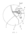
- the FIG. 1 shows a section through a section of a mold 1 with a base mold 2 and a first molded counterpart 3, wherein in the base mold 2, a perforation tool 4 is integrated.
- the perforation tool 4 is equipped with a displaceable cutting blade 5 or a displaceable perforation needle 6 and protrudes into a first cavity 7, which is formed between the base mold 2 and the first molded counterpart 3.
- the perforation tool 4 extends with the perforation needle 6 and the cutting blade 5 up to the surface of the first molded counterpart 3, so At these points when injecting the polymer material for the carrier 8 in the mold 1 breakthroughs are formed.
- the FIG. 1 shows a snapshot before the start of the actual shaping process in which the cavity 7 is not yet filled with polymer material.
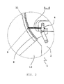
- FIG. 2 shows the same section through the same section of the mold 1 after the first injection molding cycle, in which now the carrier layer 8 is formed in the region of the first cavity 7.
- the perforation needle 6 or the cutting blade 5 of the perforation tool 4 protrudes into the carrier layer 8 and thus forms an opening 9 in the carrier layer 8.
- the FIG. 2 is a snapshot before the second injection cycle again, in which the base mold is already combined with the second molded counterpart 13, the support layer 8 is already solidified and between the two mold parts or between the second counterpart molded part 13 and the surface of the support 8, a second cavity eleventh is trained.
- FIG. 3 shows a section through the same section of the mold 1 as in the FIGS. 1 and 2 after the second injection molding cycle.
- the basic mold 2 with the integrated perforation tool 4 is combined unchanged with the second molded counterpart 13.
- the thermoplastic elastomer fills the second cavity 11 and, after having passed through an expansion stroke, a foam layer 10 with a foam core 14 and two compact edge layers 15, 16 has been formed.
- the perforation needle 6 or the cutting blade 5 of the perforation tool 4 cuts through the foam layer and is displaced as far as the more compact outer layer.
- FIG. 4 shows a section through a portion of the finished multilayer molding, from which the structure of the molding is clear.
- a foamed layer 10 is applied, which is composed of a foamed core 14 of an intermediate layer 16 and a decorative skin 15.
- This molding cutout has a predetermined breaking line 12, which extends through the carrier and foam layer up to the decorative skin 15.
- FIG. 5 shows an embodiment of the present invention with a further possibility for integration of the perforation tool 4.
- the base mold 2 of the mold 1 in the region of the first cavity 7 is equipped with nubs 17, in which the perforation tool 4 with the cutting blade 5 and the perforation 6 integrated is.
- the nubs 17 extend to the surface of the first molded counterpart 3 and thus form an opening 9 in the later carrier 8, through which the perforation element 5, 6 of the perforation tool 4 can be introduced into the foamed layer 10 in the second injection cycle.
- perforation needles 6 are used and the predetermined breaking line is formed by a juxtaposition of individual, spaced and equipped with perforation needles in the base mold 2 of the mold 1.
- the method according to the invention is not limited thereto, but it is also suitable for applying non-foamed decorative layers on a carrier material, wherein then for the second injection cycle a thermoplastic elastomer without Propellant is used and accordingly also no expandable tool counterpart must be used.
- the perforation groove also ends before the compact outer layer.
- the perforation needle or the perforation knife also being able to penetrate into the more compact outer layer, depending on the design of the decorative layer and division of the individual layers.
Landscapes
- Engineering & Computer Science (AREA)
- Mechanical Engineering (AREA)
- Manufacturing & Machinery (AREA)
- Injection Moulding Of Plastics Or The Like (AREA)
- Moulds For Moulding Plastics Or The Like (AREA)
- Air Bags (AREA)
Priority Applications (6)
| Application Number | Priority Date | Filing Date | Title |
|---|---|---|---|
| AT07020696T ATE540798T1 (de) | 2007-10-23 | 2007-10-23 | Verfahren und vorrichtung zur herstellung eines formteils mit einer sollbruchlinie für eine airbagöffnung |
| EP07020696A EP2052833B1 (fr) | 2007-10-23 | 2007-10-23 | Procédé et dispositif destinés à la fabrication d'une pièce de formage dotée d'une ligne de rupture cible en vue d'une ouverture d'airbag |
| ES07020696T ES2377574T3 (es) | 2007-10-23 | 2007-10-23 | Procedimiento y dispositivo para fabricar una pieza moldeada con una línea de rotura nominal para una abertura de airbag |
| PCT/EP2008/006953 WO2009052889A1 (fr) | 2007-10-23 | 2008-08-25 | Procédé et dispositif de fabrication d'une pièce moulée qui présente une ligne de rupture préférentielle pour l'ouverture d'un airbag |
| CN200880113039.7A CN101835585B (zh) | 2007-10-23 | 2008-08-25 | 具有用于打开安全气囊的预定断裂线的成型件的制造方法和装置 |
| US12/738,476 US20100219662A1 (en) | 2007-10-23 | 2008-08-25 | Process and device for producing a molding with a predetermined rupture line for an airbag opening |
Applications Claiming Priority (1)
| Application Number | Priority Date | Filing Date | Title |
|---|---|---|---|
| EP07020696A EP2052833B1 (fr) | 2007-10-23 | 2007-10-23 | Procédé et dispositif destinés à la fabrication d'une pièce de formage dotée d'une ligne de rupture cible en vue d'une ouverture d'airbag |
Publications (2)
| Publication Number | Publication Date |
|---|---|
| EP2052833A1 true EP2052833A1 (fr) | 2009-04-29 |
| EP2052833B1 EP2052833B1 (fr) | 2012-01-11 |
Family
ID=39272102
Family Applications (1)
| Application Number | Title | Priority Date | Filing Date |
|---|---|---|---|
| EP07020696A Active EP2052833B1 (fr) | 2007-10-23 | 2007-10-23 | Procédé et dispositif destinés à la fabrication d'une pièce de formage dotée d'une ligne de rupture cible en vue d'une ouverture d'airbag |
Country Status (6)
| Country | Link |
|---|---|
| US (1) | US20100219662A1 (fr) |
| EP (1) | EP2052833B1 (fr) |
| CN (1) | CN101835585B (fr) |
| AT (1) | ATE540798T1 (fr) |
| ES (1) | ES2377574T3 (fr) |
| WO (1) | WO2009052889A1 (fr) |
Cited By (7)
| Publication number | Priority date | Publication date | Assignee | Title |
|---|---|---|---|---|
| WO2010124751A1 (fr) | 2009-04-30 | 2010-11-04 | Peguform Gmbh | Dispositif de production d'une pièce moulée en matière plastique |
| EP2556937A1 (fr) * | 2011-08-08 | 2013-02-13 | FRIMO Group GmbH | Outil d'estampillage et de moussage ainsi que procédé |
| WO2013045087A1 (fr) * | 2011-09-27 | 2013-04-04 | Kraiburg Tpe Gmbh & Co. Kg | Élément composite constitué de matière plastique et d'élastomères thermoplastiques et procédé de fabrication dudit élément composite |
| WO2014131542A1 (fr) * | 2013-03-01 | 2014-09-04 | Johnson Controls Gmbh | Dispositif et procédé de fabrication d'un composant en mousse |
| EP2786851A1 (fr) * | 2013-04-03 | 2014-10-08 | Faurecia Automotive Industrie | Procédé de fabrication d'un élément d'insonorisation, en particulier pour un véhicule automobile |
| EP4299390A1 (fr) | 2022-06-29 | 2024-01-03 | SMRC Automotive Holdings Netherlands B.V. | Ensemble pour panneaux de garniture pour habitacle |
| US12304123B2 (en) | 2021-02-23 | 2025-05-20 | Srg Global Liria, S.L. | Pedestrian safe front panel/grille having a two-shot molded decorative part |
Families Citing this family (7)
| Publication number | Priority date | Publication date | Assignee | Title |
|---|---|---|---|---|
| US8807590B2 (en) * | 2011-08-23 | 2014-08-19 | Faurecia Interior Systems, Inc | Multi-layer vehicle airbag coverings |
| US9481338B2 (en) * | 2014-10-31 | 2016-11-01 | GM Global Technology Operations LLC | Method of manufacturing a trim component with hidden tear pattern and trim component with hidden tear pattern |
| CN106217757A (zh) * | 2016-09-07 | 2016-12-14 | 微鲸科技有限公司 | 多层注塑结构件的制造方法 |
| DE102017204963A1 (de) * | 2017-03-23 | 2018-09-27 | Bayerische Motoren Werke Aktiengesellschaft | Verkleidungselement und Herstellungsverfahren für ein Verkleidungselement |
| CN107418100B (zh) * | 2017-08-21 | 2019-09-03 | 刘子睿 | 一种汽车仪表板pvc搪塑表皮边角余料再利用方法 |
| CN108407193B (zh) * | 2018-05-04 | 2023-11-10 | 宁波尚唯汽车饰件有限公司 | 一种汽车隔音垫冲孔装置 |
| DE202021105215U1 (de) * | 2021-09-28 | 2022-01-18 | Grupo Antolín Ingeniería S.A.U. | Formbaugruppe zur Herstellung eines Armaturenbrettes für ein Fahrzeug und damit hergestelltes Armaturenbrett |
Citations (5)
| Publication number | Priority date | Publication date | Assignee | Title |
|---|---|---|---|---|
| DE19958865A1 (de) * | 1999-12-07 | 2001-06-28 | Peguform Gmbh | Luftsackabdeckvorrichtung sowie Einrichtung und Verfahren zur Herstellung einer Luftsackabdeckvorrichtung |
| US20030209890A1 (en) * | 1995-06-16 | 2003-11-13 | Chiharu Totani | Interior finish member for an automobile with an air bag device |
| EP1493545A1 (fr) * | 2003-06-30 | 2005-01-05 | Kunststoff-Technik Scherer & Trier GmbH & Co. KG | Couvercle pour airbag et procédé pour sa fabrication |
| DE102005050368A1 (de) * | 2004-10-20 | 2006-05-04 | Lear Corporation, Southfield | Kraftfahrzeug-Innenausstattungs-Baugruppe, die eine vereinigte Airbag-Tür aufweist |
| DE102005050370A1 (de) | 2004-10-20 | 2006-05-04 | Lear Corporation, Southfield | Verfahren zur Herstellung einer Kraftfahrzeug-Innenausstattungs-Baugruppe, die eine vereinigte Airbag-Tür aufweist |
Family Cites Families (4)
| Publication number | Priority date | Publication date | Assignee | Title |
|---|---|---|---|---|
| DE69627578T2 (de) * | 1995-06-21 | 2004-02-12 | Toyoda Gosei Co., Ltd. | Airbagabdeckung und Verfahren zu deren Herstellung |
| US20020135161A1 (en) * | 2001-03-26 | 2002-09-26 | Lamb Tony M. | Glass fiber reinforced thermoplastic components |
| JP4465929B2 (ja) * | 2001-07-05 | 2010-05-26 | 株式会社プライムポリマー | 熱可塑性樹脂組成物発泡体の製造方法 |
| DE10234198B4 (de) * | 2001-07-27 | 2007-04-19 | Toyoda Gosei Co., Ltd. | Verfahren zum Herstellen eines Fahrzeuginnenraumgegenstands sowie Gegenstand |
-
2007
- 2007-10-23 AT AT07020696T patent/ATE540798T1/de active
- 2007-10-23 EP EP07020696A patent/EP2052833B1/fr active Active
- 2007-10-23 ES ES07020696T patent/ES2377574T3/es active Active
-
2008
- 2008-08-25 US US12/738,476 patent/US20100219662A1/en not_active Abandoned
- 2008-08-25 CN CN200880113039.7A patent/CN101835585B/zh not_active Expired - Fee Related
- 2008-08-25 WO PCT/EP2008/006953 patent/WO2009052889A1/fr not_active Ceased
Patent Citations (5)
| Publication number | Priority date | Publication date | Assignee | Title |
|---|---|---|---|---|
| US20030209890A1 (en) * | 1995-06-16 | 2003-11-13 | Chiharu Totani | Interior finish member for an automobile with an air bag device |
| DE19958865A1 (de) * | 1999-12-07 | 2001-06-28 | Peguform Gmbh | Luftsackabdeckvorrichtung sowie Einrichtung und Verfahren zur Herstellung einer Luftsackabdeckvorrichtung |
| EP1493545A1 (fr) * | 2003-06-30 | 2005-01-05 | Kunststoff-Technik Scherer & Trier GmbH & Co. KG | Couvercle pour airbag et procédé pour sa fabrication |
| DE102005050368A1 (de) * | 2004-10-20 | 2006-05-04 | Lear Corporation, Southfield | Kraftfahrzeug-Innenausstattungs-Baugruppe, die eine vereinigte Airbag-Tür aufweist |
| DE102005050370A1 (de) | 2004-10-20 | 2006-05-04 | Lear Corporation, Southfield | Verfahren zur Herstellung einer Kraftfahrzeug-Innenausstattungs-Baugruppe, die eine vereinigte Airbag-Tür aufweist |
Cited By (9)
| Publication number | Priority date | Publication date | Assignee | Title |
|---|---|---|---|---|
| WO2010124751A1 (fr) | 2009-04-30 | 2010-11-04 | Peguform Gmbh | Dispositif de production d'une pièce moulée en matière plastique |
| EP2556937A1 (fr) * | 2011-08-08 | 2013-02-13 | FRIMO Group GmbH | Outil d'estampillage et de moussage ainsi que procédé |
| WO2013045087A1 (fr) * | 2011-09-27 | 2013-04-04 | Kraiburg Tpe Gmbh & Co. Kg | Élément composite constitué de matière plastique et d'élastomères thermoplastiques et procédé de fabrication dudit élément composite |
| WO2014131542A1 (fr) * | 2013-03-01 | 2014-09-04 | Johnson Controls Gmbh | Dispositif et procédé de fabrication d'un composant en mousse |
| EP2786851A1 (fr) * | 2013-04-03 | 2014-10-08 | Faurecia Automotive Industrie | Procédé de fabrication d'un élément d'insonorisation, en particulier pour un véhicule automobile |
| WO2014161959A1 (fr) * | 2013-04-03 | 2014-10-09 | Faurecia Automotive Industrie | Procédé permettant de fabriquer un élément phono-absorbant, en particulier pour un véhicule à moteur |
| US12304123B2 (en) | 2021-02-23 | 2025-05-20 | Srg Global Liria, S.L. | Pedestrian safe front panel/grille having a two-shot molded decorative part |
| EP4299390A1 (fr) | 2022-06-29 | 2024-01-03 | SMRC Automotive Holdings Netherlands B.V. | Ensemble pour panneaux de garniture pour habitacle |
| FR3137338A1 (fr) | 2022-06-29 | 2024-01-05 | Smrc Automotive Holdings Netherlands B.V. | Ensemble pour panneaux de garniture pour habitacle |
Also Published As
| Publication number | Publication date |
|---|---|
| CN101835585B (zh) | 2014-08-27 |
| CN101835585A (zh) | 2010-09-15 |
| ATE540798T1 (de) | 2012-01-15 |
| EP2052833B1 (fr) | 2012-01-11 |
| WO2009052889A1 (fr) | 2009-04-30 |
| US20100219662A1 (en) | 2010-09-02 |
| ES2377574T3 (es) | 2012-03-29 |
Similar Documents
| Publication | Publication Date | Title |
|---|---|---|
| EP2052833B1 (fr) | Procédé et dispositif destinés à la fabrication d'une pièce de formage dotée d'une ligne de rupture cible en vue d'une ouverture d'airbag | |
| DE69912524T2 (de) | Verfahren zum Herstellen eines Kraftfahrzeugverkleidungsteils mit Schwächungslinien für eine Airbag-Entfaltungsöffnung | |
| EP2113429B1 (fr) | Habillage intérieur doté d'un recouvrement d'airbag intégré | |
| EP2641786B1 (fr) | Pièce d'équipement intérieur, en particulier tableau de bord avec clapet d'airbag | |
| DE10334274B3 (de) | Schallisolierendes Verbundteil und Verfahren zu dessen Herstellung | |
| DE102007002309B4 (de) | Vorrichtung und Verfahren zur Herstellung eines Kunststoffbauteils | |
| EP2112025B1 (fr) | Composant d'habillage intérieur pour véhicules automobiles | |
| EP2015912B1 (fr) | Procede pour produire une piece moulee munie d'une rainure d'ouverture | |
| EP1952964B1 (fr) | Procédé de fabrication d'un tableau de bord | |
| DE102016015465A1 (de) | Verfahren zum Herstellen eines Sandwichbauteils | |
| DE102005050370A1 (de) | Verfahren zur Herstellung einer Kraftfahrzeug-Innenausstattungs-Baugruppe, die eine vereinigte Airbag-Tür aufweist | |
| EP2424718B1 (fr) | Dispositif de production d'une pièce moulée en matière plastique | |
| DE102007060584A1 (de) | Dekorhaut für eine Airbagabdeckung | |
| DE102013018578B4 (de) | Verfahren zur Herstellung eines polyurethanüberfluteten Kunststoffbauteils | |
| EP2556937B1 (fr) | Outil d'estampillage et de moussage ainsi que procédé | |
| DE102007009384A1 (de) | Verfahren zum Hinterspritzen einer Schaumfolie | |
| DE102021113280A1 (de) | Abdeckung für eine Airbag-Einrichtung, Innenverkleidungsteil und Verfahren zur Herstellung einer Abdeckung | |
| DE10110908B4 (de) | Verfahren zur Herstellung eines mehrschichtigen Verbundteils und Werkzeug | |
| DE102008044026B4 (de) | Verfahren zur Herstellung eines Verbundbauteils und dadurch hergestelltes Verbundbauteil | |
| DE102014207948B4 (de) | Verfahren zum stoffschlüssigen Verbinden von Fahrzeugbauteilen | |
| DE102016005954B4 (de) | Verfahren und Vorrichtung zur Herstellung eines thermoplastischen Schaumgussbauteils mit wenigstens einer Sollbruchstelle | |
| DE102006004816A1 (de) | Verfahren zum Herstellen eines Verbundteils mit Hinterschnitt | |
| EP2139658B1 (fr) | Procédé permettant de fabriquer des éléments en plastique expansé | |
| EP1958759B1 (fr) | Procédé de fabrication d'un recouvrement d'airbag | |
| WO2018149742A1 (fr) | Procédé de fabrication d'une unité intérieure pour un véhicule à moteur et unité intérieure pour un véhicule à moteur |
Legal Events
| Date | Code | Title | Description |
|---|---|---|---|
| PUAI | Public reference made under article 153(3) epc to a published international application that has entered the european phase |
Free format text: ORIGINAL CODE: 0009012 |
|
| AK | Designated contracting states |
Kind code of ref document: A1 Designated state(s): AT BE BG CH CY CZ DE DK EE ES FI FR GB GR HU IE IS IT LI LT LU LV MC MT NL PL PT RO SE SI SK TR |
|
| AX | Request for extension of the european patent |
Extension state: AL BA HR MK RS |
|
| 17P | Request for examination filed |
Effective date: 20090520 |
|
| 17Q | First examination report despatched |
Effective date: 20090624 |
|
| AKX | Designation fees paid |
Designated state(s): AT BE BG CH CY CZ DE DK EE ES FI FR GB GR HU IE IS IT LI LT LU LV MC MT NL PL PT RO SE SI SK TR |
|
| GRAP | Despatch of communication of intention to grant a patent |
Free format text: ORIGINAL CODE: EPIDOSNIGR1 |
|
| GRAS | Grant fee paid |
Free format text: ORIGINAL CODE: EPIDOSNIGR3 |
|
| GRAA | (expected) grant |
Free format text: ORIGINAL CODE: 0009210 |
|
| AK | Designated contracting states |
Kind code of ref document: B1 Designated state(s): AT BE BG CH CY CZ DE DK EE ES FI FR GB GR HU IE IS IT LI LT LU LV MC MT NL PL PT RO SE SI SK TR |
|
| REG | Reference to a national code |
Ref country code: GB Ref legal event code: FG4D Free format text: NOT ENGLISH |
|
| REG | Reference to a national code |
Ref country code: CH Ref legal event code: EP |
|
| REG | Reference to a national code |
Ref country code: AT Ref legal event code: REF Ref document number: 540798 Country of ref document: AT Kind code of ref document: T Effective date: 20120115 |
|
| REG | Reference to a national code |
Ref country code: IE Ref legal event code: FG4D |
|
| REG | Reference to a national code |
Ref country code: DE Ref legal event code: R096 Ref document number: 502007009034 Country of ref document: DE Effective date: 20120315 |
|
| REG | Reference to a national code |
Ref country code: ES Ref legal event code: FG2A Ref document number: 2377574 Country of ref document: ES Kind code of ref document: T3 Effective date: 20120329 |
|
| REG | Reference to a national code |
Ref country code: NL Ref legal event code: VDEP Effective date: 20120111 |
|
| PG25 | Lapsed in a contracting state [announced via postgrant information from national office to epo] |
Ref country code: SI Free format text: LAPSE BECAUSE OF FAILURE TO SUBMIT A TRANSLATION OF THE DESCRIPTION OR TO PAY THE FEE WITHIN THE PRESCRIBED TIME-LIMIT Effective date: 20120111 |
|
| RAP2 | Party data changed (patent owner data changed or rights of a patent transferred) |
Owner name: SMP DEUTSCHLAND GMBH |
|
| LTIE | Lt: invalidation of european patent or patent extension |
Effective date: 20120111 |
|
| PG25 | Lapsed in a contracting state [announced via postgrant information from national office to epo] |
Ref country code: BG Free format text: LAPSE BECAUSE OF FAILURE TO SUBMIT A TRANSLATION OF THE DESCRIPTION OR TO PAY THE FEE WITHIN THE PRESCRIBED TIME-LIMIT Effective date: 20120411 Ref country code: IS Free format text: LAPSE BECAUSE OF FAILURE TO SUBMIT A TRANSLATION OF THE DESCRIPTION OR TO PAY THE FEE WITHIN THE PRESCRIBED TIME-LIMIT Effective date: 20120511 Ref country code: NL Free format text: LAPSE BECAUSE OF FAILURE TO SUBMIT A TRANSLATION OF THE DESCRIPTION OR TO PAY THE FEE WITHIN THE PRESCRIBED TIME-LIMIT Effective date: 20120111 Ref country code: LT Free format text: LAPSE BECAUSE OF FAILURE TO SUBMIT A TRANSLATION OF THE DESCRIPTION OR TO PAY THE FEE WITHIN THE PRESCRIBED TIME-LIMIT Effective date: 20120111 |
|
| REG | Reference to a national code |
Ref country code: IE Ref legal event code: FD4D |
|
| PG25 | Lapsed in a contracting state [announced via postgrant information from national office to epo] |
Ref country code: PL Free format text: LAPSE BECAUSE OF FAILURE TO SUBMIT A TRANSLATION OF THE DESCRIPTION OR TO PAY THE FEE WITHIN THE PRESCRIBED TIME-LIMIT Effective date: 20120111 Ref country code: FI Free format text: LAPSE BECAUSE OF FAILURE TO SUBMIT A TRANSLATION OF THE DESCRIPTION OR TO PAY THE FEE WITHIN THE PRESCRIBED TIME-LIMIT Effective date: 20120111 Ref country code: LV Free format text: LAPSE BECAUSE OF FAILURE TO SUBMIT A TRANSLATION OF THE DESCRIPTION OR TO PAY THE FEE WITHIN THE PRESCRIBED TIME-LIMIT Effective date: 20120111 Ref country code: PT Free format text: LAPSE BECAUSE OF FAILURE TO SUBMIT A TRANSLATION OF THE DESCRIPTION OR TO PAY THE FEE WITHIN THE PRESCRIBED TIME-LIMIT Effective date: 20120511 Ref country code: GR Free format text: LAPSE BECAUSE OF FAILURE TO SUBMIT A TRANSLATION OF THE DESCRIPTION OR TO PAY THE FEE WITHIN THE PRESCRIBED TIME-LIMIT Effective date: 20120412 |
|
| PG25 | Lapsed in a contracting state [announced via postgrant information from national office to epo] |
Ref country code: CY Free format text: LAPSE BECAUSE OF FAILURE TO SUBMIT A TRANSLATION OF THE DESCRIPTION OR TO PAY THE FEE WITHIN THE PRESCRIBED TIME-LIMIT Effective date: 20120111 |
|
| PG25 | Lapsed in a contracting state [announced via postgrant information from national office to epo] |
Ref country code: IE Free format text: LAPSE BECAUSE OF FAILURE TO SUBMIT A TRANSLATION OF THE DESCRIPTION OR TO PAY THE FEE WITHIN THE PRESCRIBED TIME-LIMIT Effective date: 20120111 Ref country code: EE Free format text: LAPSE BECAUSE OF FAILURE TO SUBMIT A TRANSLATION OF THE DESCRIPTION OR TO PAY THE FEE WITHIN THE PRESCRIBED TIME-LIMIT Effective date: 20120111 Ref country code: DK Free format text: LAPSE BECAUSE OF FAILURE TO SUBMIT A TRANSLATION OF THE DESCRIPTION OR TO PAY THE FEE WITHIN THE PRESCRIBED TIME-LIMIT Effective date: 20120111 Ref country code: SE Free format text: LAPSE BECAUSE OF FAILURE TO SUBMIT A TRANSLATION OF THE DESCRIPTION OR TO PAY THE FEE WITHIN THE PRESCRIBED TIME-LIMIT Effective date: 20120111 Ref country code: RO Free format text: LAPSE BECAUSE OF FAILURE TO SUBMIT A TRANSLATION OF THE DESCRIPTION OR TO PAY THE FEE WITHIN THE PRESCRIBED TIME-LIMIT Effective date: 20120111 |
|
| PLBE | No opposition filed within time limit |
Free format text: ORIGINAL CODE: 0009261 |
|
| STAA | Information on the status of an ep patent application or granted ep patent |
Free format text: STATUS: NO OPPOSITION FILED WITHIN TIME LIMIT |
|
| PG25 | Lapsed in a contracting state [announced via postgrant information from national office to epo] |
Ref country code: SK Free format text: LAPSE BECAUSE OF FAILURE TO SUBMIT A TRANSLATION OF THE DESCRIPTION OR TO PAY THE FEE WITHIN THE PRESCRIBED TIME-LIMIT Effective date: 20120111 |
|
| 26N | No opposition filed |
Effective date: 20121012 |
|
| REG | Reference to a national code |
Ref country code: DE Ref legal event code: R097 Ref document number: 502007009034 Country of ref document: DE Effective date: 20121012 |
|
| BERE | Be: lapsed |
Owner name: PEGUFORM G.M.B.H. Effective date: 20121031 |
|
| PG25 | Lapsed in a contracting state [announced via postgrant information from national office to epo] |
Ref country code: MC Free format text: LAPSE BECAUSE OF NON-PAYMENT OF DUE FEES Effective date: 20121031 |
|
| REG | Reference to a national code |
Ref country code: CH Ref legal event code: PL |
|
| PG25 | Lapsed in a contracting state [announced via postgrant information from national office to epo] |
Ref country code: LI Free format text: LAPSE BECAUSE OF NON-PAYMENT OF DUE FEES Effective date: 20121031 Ref country code: BE Free format text: LAPSE BECAUSE OF NON-PAYMENT OF DUE FEES Effective date: 20121031 Ref country code: CH Free format text: LAPSE BECAUSE OF NON-PAYMENT OF DUE FEES Effective date: 20121031 |
|
| PG25 | Lapsed in a contracting state [announced via postgrant information from national office to epo] |
Ref country code: MT Free format text: LAPSE BECAUSE OF FAILURE TO SUBMIT A TRANSLATION OF THE DESCRIPTION OR TO PAY THE FEE WITHIN THE PRESCRIBED TIME-LIMIT Effective date: 20120111 |
|
| REG | Reference to a national code |
Ref country code: AT Ref legal event code: MM01 Ref document number: 540798 Country of ref document: AT Kind code of ref document: T Effective date: 20121031 |
|
| PG25 | Lapsed in a contracting state [announced via postgrant information from national office to epo] |
Ref country code: AT Free format text: LAPSE BECAUSE OF NON-PAYMENT OF DUE FEES Effective date: 20121031 |
|
| PG25 | Lapsed in a contracting state [announced via postgrant information from national office to epo] |
Ref country code: TR Free format text: LAPSE BECAUSE OF FAILURE TO SUBMIT A TRANSLATION OF THE DESCRIPTION OR TO PAY THE FEE WITHIN THE PRESCRIBED TIME-LIMIT Effective date: 20120111 |
|
| PG25 | Lapsed in a contracting state [announced via postgrant information from national office to epo] |
Ref country code: LU Free format text: LAPSE BECAUSE OF NON-PAYMENT OF DUE FEES Effective date: 20121023 |
|
| PG25 | Lapsed in a contracting state [announced via postgrant information from national office to epo] |
Ref country code: HU Free format text: LAPSE BECAUSE OF FAILURE TO SUBMIT A TRANSLATION OF THE DESCRIPTION OR TO PAY THE FEE WITHIN THE PRESCRIBED TIME-LIMIT Effective date: 20071023 |
|
| REG | Reference to a national code |
Ref country code: FR Ref legal event code: PLFP Year of fee payment: 9 |
|
| REG | Reference to a national code |
Ref country code: FR Ref legal event code: PLFP Year of fee payment: 10 |
|
| REG | Reference to a national code |
Ref country code: FR Ref legal event code: PLFP Year of fee payment: 11 |
|
| PGFP | Annual fee paid to national office [announced via postgrant information from national office to epo] |
Ref country code: CZ Payment date: 20171013 Year of fee payment: 11 |
|
| PGFP | Annual fee paid to national office [announced via postgrant information from national office to epo] |
Ref country code: GB Payment date: 20171024 Year of fee payment: 11 Ref country code: IT Payment date: 20171020 Year of fee payment: 11 |
|
| REG | Reference to a national code |
Ref country code: FR Ref legal event code: PLFP Year of fee payment: 12 |
|
| GBPC | Gb: european patent ceased through non-payment of renewal fee |
Effective date: 20181023 |
|
| PG25 | Lapsed in a contracting state [announced via postgrant information from national office to epo] |
Ref country code: CZ Free format text: LAPSE BECAUSE OF NON-PAYMENT OF DUE FEES Effective date: 20181023 |
|
| PG25 | Lapsed in a contracting state [announced via postgrant information from national office to epo] |
Ref country code: IT Free format text: LAPSE BECAUSE OF NON-PAYMENT OF DUE FEES Effective date: 20181023 Ref country code: GB Free format text: LAPSE BECAUSE OF NON-PAYMENT OF DUE FEES Effective date: 20181023 |
|
| P01 | Opt-out of the competence of the unified patent court (upc) registered |
Effective date: 20230427 |
|
| PGFP | Annual fee paid to national office [announced via postgrant information from national office to epo] |
Ref country code: DE Payment date: 20251020 Year of fee payment: 19 |
|
| PGFP | Annual fee paid to national office [announced via postgrant information from national office to epo] |
Ref country code: FR Payment date: 20251022 Year of fee payment: 19 |
|
| PGFP | Annual fee paid to national office [announced via postgrant information from national office to epo] |
Ref country code: ES Payment date: 20251114 Year of fee payment: 19 |