EP2052907A2 - Poignée d'assistance - Google Patents
Poignée d'assistance Download PDFInfo
- Publication number
- EP2052907A2 EP2052907A2 EP08253124A EP08253124A EP2052907A2 EP 2052907 A2 EP2052907 A2 EP 2052907A2 EP 08253124 A EP08253124 A EP 08253124A EP 08253124 A EP08253124 A EP 08253124A EP 2052907 A2 EP2052907 A2 EP 2052907A2
- Authority
- EP
- European Patent Office
- Prior art keywords
- grip
- rotation arm
- grip member
- retraction
- rotation
- Prior art date
- Legal status (The legal status is an assumption and is not a legal conclusion. Google has not performed a legal analysis and makes no representation as to the accuracy of the status listed.)
- Granted
Links
- 241000282472 Canis lupus familiaris Species 0.000 description 8
- 238000000034 method Methods 0.000 description 1
- 238000012986 modification Methods 0.000 description 1
- 230000004048 modification Effects 0.000 description 1
Images





Classifications
-
- B—PERFORMING OPERATIONS; TRANSPORTING
- B60—VEHICLES IN GENERAL
- B60N—SEATS SPECIALLY ADAPTED FOR VEHICLES; VEHICLE PASSENGER ACCOMMODATION NOT OTHERWISE PROVIDED FOR
- B60N3/00—Arrangements or adaptations of other passenger fittings, not otherwise provided for
- B60N3/02—Arrangements or adaptations of other passenger fittings, not otherwise provided for of hand grips or straps
- B60N3/023—Arrangements or adaptations of other passenger fittings, not otherwise provided for of hand grips or straps movable
Definitions
- the present invention relates to a retractable assist grip which a passenger uses to keep his/her riding posture in an interior of a vehicle such as an automobile.
- a vehicle such as an automobile is provided with an assist grip in its interior so that a passenger can use the assist grip to keep his/her riding posture when the vehicle body shakes.
- an assist grip is installed in the vicinity of a roof-side rail in the vehicle interior, and has a handle shape to provide a comfortable grip for a passenger.
- the pull-out type assist grip has a grip member, which is retracted in a housing member while not in use. Depending on the necessity, a passenger pulls out the grip member from the retraction position to use it.
- Patent Document 1 discloses an assist grip having a configuration in which its grip member is rotatable from a retraction position to a grip position.
- the grip member is in the retraction position while retracted, and is in the grip position allowing a passenger to grip the grip member with fingers, after the passenger pulls out from the retraction position.
- the assist grip disclosed in Patent Document 1 includes an alternate type lock system and a spring.
- the lock system has a function of holding the grip member in the retraction position; and a function of releasing the grip member from being held when the grip member located in the retraction position is further pushed in.
- the spring is configured to bias the grip member toward the grip position.
- the grip member in the retracted position is unlocked when pushed with fingers, and thereby the grip member is automatically rotates to the grip position by being biased by the spring. This condition allows a passenger to grip the grip member, and thus to keep his/her riding posture even if the vehicle shakes.
- the grip member having a U-shape, is directly attached to the vehicle by use of rotation shafts. Accordingly, the grip member is exposed enough for a passenger to see the whole appearance of a side surface thereof even while retracted in the housing member.
- the assist grip disclosed in Patent Document 1 has a problem of having a poor appearance while the grip member is retracted in the housing member.
- the grip member disclosed in Patent Document 1 is directly attached to the vehicle in a manner that two bearing parts extending downward from both end portions of a grip part are attached to the vehicle by use of the two rotation shafts, respectively. For this reason, in order to retract the grip member into the housing member, the grip part of the grip member needs to be rotated to a higher position against a biasing force of the spring. Additionally, after rotated to the higher position, the grip part located there further needs to be pushed into the housing member to be locked by the alternate type lock system. For this reason, the passenger has to extend his/her fingers above the location to which the assist grip is attached. This makes the grip member disclosed in Patent Document 1 difficult to use.
- the assist grip disclosed in Patent Document 1 is of a push-open type using the alternate type lock system, a passenger has to rearrange his/her fingers from when unlocking the grip member to pull out the grip member to when actually griping the grip member.
- the assist grip disclosed in Patent Document 1 is not user-friendly.
- an assist grip to be provided in an interior of a vehicle, including: a grip member to be gripped by a passenger, the grip member configured to be capable of being pulled out from a retraction position to a grip position; a base member which is fixed to the vehicle and which includes a rotation shaft; a rotation arm pivotally supported so as to be rotatable about the rotation shaft from the retraction position to a pull-out position; retraction biasing means configured to always bias the rotation arm in a retraction direction; and a holding member configured to hold the rotation arm in the pull-out position against a biasing force of the retraction biasing means when the rotation arm is caused to rotate to the pull-out position, wherein the grip member is rotatably jointed to the rotation arm, and the grip member is provided with a release dog formed therein, the release dog configured to release the rotation arm from being held by the holding member as the grip member is rotated.
- the assist grip further includes engagement biasing means, wherein the holding member is pivotally swingably supported by part of the rotation arm by use of a swing shaft, the base member is provided with a projection part formed therein, the projection part configured to keep the rotation arm held by the holding member by engaging with an engagement part formed in part of the holding member, and the engagement biasing means configured to bias the engagement part toward the projection part.
- the assist grip further includes guide means configured to guide a movement of the grip member while kept in contact with the grip member, when the grip member moves between the retraction position and the grip position with the rotation arm.
- the rotation arm of the assist grip rotates to the pull-out position.
- the rotation arm is held in the pull-out position against the biasing of the retraction biasing means due to the operations of the respective holding members.
- the grip member rotatably jointed to the rotation arm is held in the grip position.
- the passenger causes the grip member so far gripped by himself/herself to rotate upward.
- the release dogs switch the rotation arm from the condition in which the rotation arm is held by the holding members to a condition in which the rotation arm is rotatable.
- the biasing force of the retraction biasing means automatically causes the rotation arm to rotate to the retraction position.
- the grip member jointed to the rotation arm also automatically returns to the retraction position in response to the rotation arm. This makes it easy to pull out and retract the grip member.
- the holding members are pivotally swingably supported by the rotation arm.
- the engagement parts of the holding members are biased to the projection parts of the base member by use of the engagement biasing means respectively.
- the release dogs formed in the grip member release the rotation arm from the held condition in which the rotation arm is held by the holding members, and thus switch the rotation arm to a condition in which the rotation arm is rotatable. Thereby, the grip member returns to the retraction position with the rotation arm.
- the assist grip further includes the guide means for guiding a movement of the grip member while kept in contact with the grip member when the grip member moves between the retraction position and the grip position. This makes it possible to reduce the sliding resistance which occurs when the grip member moves, and accordingly allows the grip member to be pulled out and retracted smoothly.
- Fig. 1 is an external view of an assist grip 10, viewed from a vehicle interior, which allows a grip member 50 to be retracted into a space part provided in the rear of a vehicle interior body 8.
- Fig. 1 shows how a passenger pulls out the grip member 50 retracted in its retraction position with fingers. Note that components recessed in the rear of the interior body 8 are indicated with broken lines.
- Fig. 2 is an external view showing the grip member 50 of the assist grip 10 shown in Fig. 1 , which is pulled out from its retraction position to its grip position.
- Fig. 3 is an exploded, perspective view of the assist grip 10 according to the present invention.
- Fig. 4 is an exploded, perspective view of a handle 38 of the assist grip shown in Fig. 3 .
- Fig. 5 is an exploded, perspective view of a case 60 which the handle 38 is retracted into and pulled out from.
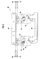
- Fig. 6 is an external, perspective view of the structure of the assist grip 10, observed from the space part provided in the rear of the interior body 8.
- the assist grip 10 is fixed to a side rail 6 set between the outer panel of the vehicle and the interior body 8.
- a mechanism of the assist grip 10 configured to allow the grip member 50 to move from its retraction position to its grip position is arranged in the space part between this side rail 6 and the interior body 8.
- the assist grip 10 includes a base member 20 fixed to the side rail 6 of the vehicle.
- a rotation shaft 22 and a rear supporter 24 are attached to the base member 20.
- the rotation shaft 22 is configured to pivotally support the rotation arm 40 so as to be rotatable.
- the rear supporter 24 is configured to position the rotationally-biased rotation arm 40 in the retraction position.
- the rotation shaft 22 is inserted through a rotation base 41, two rotation gears 30, and a retraction biasing means 28.
- the rotation base 41 holds the rotation arm 40.
- the two rotation gears 30 rotate together with the rotation base 41.
- the retraction biasing means 28 always biases the rotation arm 40 in a retraction direction by engaging with both of the base member 20 and the rotation base 41.
- the rotation arm 40 of the handle 38 is attached to the rotation base 41.
- the handle 38 together with the rotation base 41 is pivotally supported about the rotation shaft 22 so as to be rotatable with the base member 20 from the retraction position to the pull-out position.
- a torsion spring as shown in Fig. 3 may be used as the retraction biasing means 28.
- the handle 38 can always be rotationally biased in a direction toward its retraction position by the biasing force of the retraction biasing means 28.
- the base member 20 includes two dampers 34 each configured to impart non-elastic resistance to the rotation arm 40 depending on its rotational speed.
- Damper gears 32 are fixed to the rotation shafts of the dampers 34, respectively.
- the damper gears 32 are configured to mesh with the rotation gears 30 rotating about the rotation shaft 22, respectively. This makes it possible to keep slow the rotational speed of the handle 38 which moves rotationally in the direction toward the retraction position due to the biasing force of the retraction biasing means 28, and concurrently to give a graceful impression to the retraction operation of the grip member 50.
- the grip member 50 is jointed to the rotation arm 40 by use of jointing shafts 42 for jointing the grip member 50 and the rotation arm 40 together so as to be rotatable from the ready-to-retract condition (see Figs. 7 , 9 and 10 ) to the grip position (see Fig. 8 ).
- the handle 38 rotates about the rotation shaft 22 from the retraction position to the pull-out position.
- the grip member 50 rotates with the rotation arm 40 from the ready-to-retract condition to the grip position.
- the handle 38 is configured to be capable of being pulled out from an opening portion opened in the middle of the case 60 to the vehicle interior.
- the case 60 is fixed to the base member 20.
- Fig. 4 the rotation arm 40 and the grip member 50 constituting the handle 38 are rotatably jointed together by use of the two jointing shafts 42.
- Swing shafts 46 configured to pivotally swingably support holding members 44 are attached to parts of the rotation arm 40, respectively.
- the two holding members 44 are provided in the vicinities of the two jointing shafts 42 for jointing the grip member 50 to the rotation arm 40, respectively.
- Engagement biasing means 45 are attached to the respective holding members 44.
- the engagement biasing means 45 bias the respective engagement parts 43 outward (toward the respective projection parts 21 shown in Fig. 8 , to be described later).
- the engagement parts 43 are formed in end portions of the holding members 44, respectively. An end portion of each engagement biasing means 45 engages with its corresponding holding member 44, and the other end portion of the engagement biasing means 45 engages with the rotation arm 40.
- releasing dogs 52 are formed in top portions of the grip member 50, the top portions being located in the outer peripheries of bearing parts for the jointing shafts 42, respectively.
- the engagement parts 43 are biased outward by the biasing forces of the engagement biasing means 45, the releasing dogs 52 cause the engagement parts 43 to rotate inward against the biasing forces of the engagement biasing means 45, respectively.
- Figs. 8 to 10 for a relationship among operations of the holding members 44, operations of the releasing dogs 52 and the projection parts 21 formed in the base member 20.
- the case 60 which the handle 38 is pulled out from and retracted into includes: an inner case 62 arranged in the rear; an outer case 64 arranged to be exposed to the vehicle interior; and roller cases 66 for holding the respective roller-shaped guide means 68.
- Each guide means 68 guides the movement of the grip member 50 while being kept in contact with the grip member 50 when the grip member 50 moves between the retraction position and the grip position in response to the rotation of the rotation arm 40, and plays a function of reducing the sliding resistance.
- Fig. 6 shows the assist grip 10 in which the handle 38 is retracted into its retraction position.
- the rear supporter 24 is fixed to the base member 20.
- the rotation base 41 rotationally biased by the movement of the retraction biasing means 28 is positioned in the retraction position.
- the two dampers 34 are attached to the base member 20.
- the damper gears 32 fixed to the rotation shafts of the dampers 34 engage with the rotation gears 30, respectively. This makes it possible to slowly return the rotation arm 40 and the grip member 50 attached to the rotation base 41 to the retraction position.
- the grip member 50 is rotatably jointed to the rotation arm 40 by use of the two jointing shafts 42.
- the two holding members 44 are pivotally swingably supported with the rotation arm 40 about their respective swing shafts 46.
- the engagement biasing means 45 engage with the respective holding members 44 and the rotation arm 40.
- the engagement biasing means 45 bias the engagement parts 43 formed in the holding members 44 outward, respectively.
- the engagement parts 43 engage with the projection parts 21 formed in the base member 20 when the rotation arm 40 rotate to the pull-out position by pulling out the grip member 50.
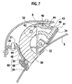
- Figs. 7 to 10 are the side, cross-sectional views taken along the X-X line of Fig. 6 .
- Fig. 7 is a side, cross-sectional view showing the assist grip 10 whose grip member 50 is located in the retraction position.
- Fig. 8 is a side, cross-sectional view showing the assist grip whose grip member 50 is located in the grip position.
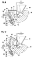
- Fig. 9 is a side, cross-sectional view showing the assist grip whose grip member 50 is caused to rotate to the ready-to-retract position by causing the grip member 50 to rotate upward about the jointing shafts 42 from the grip position shown in Fig. 8 .
- Fig. 10 is a side, cross-sectional view showing the assist grip whose handle 38 rotates to the retraction position from the pull-out position shown in Fig. 9 .
- the illustrations respectively of the dampers 34, the damper gears 32 and the rotation gears 30 are omitted here.
- the retraction biasing means 28 biases, clockwisely in Fig. 7 , the rotation base 41, the rotation arm 40 and the grip member 50. Subsequently, when the rotation base 41 comes in contact with the rear supporter 24, the rotation base 41, the rotation arm 40 and the grip member 50 are held in the halting state in the retraction position. As a result, as shown in Figs. 7 and 1 , the rotation base 41, the rotation arm 40 and the grip member 50 are put in the state of being retracted inside the interior body 8.
- the passenger can easily pull out the grip member 50 retracted in the retraction position with fingers against the biasing force of the retraction biasing means 28.
- the rotation base 41 and the rotation arm 40 start to rotate counterclockwisely in Fig. 7 .
- the grip member 50 rotatably jointed to the rotation arm 40 with the rotation arm 40 comes to the grip position after rotating clockwisely with the rotation arm 40, and is thus put in the condition shown in Figs. 2 and 8 .
- the holding members 44 to be pivotally swingably supported by the rotation arm 40 are attached to the parts of the rotation arm 40 by use of the respective swing shafts 46.
- the engagement parts 43 engage with the projection parts 21 of the base member 20 are formed in the ends of the holding members 44, respectively.
- the grip member 50 rotatably jointed to the rotation arm 40 comes to the grip position shown in Fig. 2 after rotating clockwisely with the rotation arm 40. Accordingly, the grip member 50 is held in a position where the passenger can easily grip the grip member 50.
- the rotation arm 40 When the engagement parts 43 are separated from the respective projection parts 21, the rotation arm 40 is released from the held condition, and is thus switched in the rotation condition. Hence, the rotation arm 40 rotates to the retraction position due to the biasing force of the retraction biasing means 28 (see Fig. 10 ).
- Fig. 10 is a view showing grip member 50 being in the process of moving from the ready-to-retract position to the retraction position together with the rotation arm 40.
- the rotation arm 40 rotates to the retraction position while being biased by the retraction biasing means 28.
- the rotation arm 40 rotates to the retraction position shown in Fig. 7 holding a constant angular velocity by the operations of the respective dampers 34 shown in Figs. 3 and 6 . This makes it possible to impart a graceful impression to the retraction operation of the grip member 50.
- roller-shaped guide means 68 guides the movement of the grip member 50 while rotating in contact with the grip member 50. This guiding scheme reduces the sliding resistance which occurs when the grip member 50 moves, and thus allows the grip member 50 to be pulled out and retracted smoothly.
- the rotation arm 40 is held by engaging the holding members 44 with the respective projection parts 21 formed in the base member 20, the holding members 44 being pivotally supported by the part of the rotation arm 40 by use of the swing shafts 46.
- the present invention is not limited to the foregoing embodiment.
- An object of the present invention can be achieved, for example, by arranging the holding members in the base member, and concurrently by forming the projection parts for engaging with parts of the holding members in the rotation arm.
- the holding members are not limited to the swing type. Instead, the holding members may be configured to switch between a holding condition and a rotation condition by use of direct-acting members such as plungers.
- the assist grip according to the present invention is applicable to a retractable handle attached to a vehicle exterior, a door, a bag and the like in addition to the vehicle interior.
Landscapes
- Engineering & Computer Science (AREA)
- Transportation (AREA)
- Mechanical Engineering (AREA)
- Passenger Equipment (AREA)
Applications Claiming Priority (1)
| Application Number | Priority Date | Filing Date | Title |
|---|---|---|---|
| JP2007247810A JP5242977B2 (ja) | 2007-09-25 | 2007-09-25 | アシストグリップ |
Publications (3)
| Publication Number | Publication Date |
|---|---|
| EP2052907A2 true EP2052907A2 (fr) | 2009-04-29 |
| EP2052907A3 EP2052907A3 (fr) | 2012-12-19 |
| EP2052907B1 EP2052907B1 (fr) | 2014-05-07 |
Family
ID=40435043
Family Applications (1)
| Application Number | Title | Priority Date | Filing Date |
|---|---|---|---|
| EP08253124.5A Not-in-force EP2052907B1 (fr) | 2007-09-25 | 2008-09-24 | Poignée d'assistance |
Country Status (4)
| Country | Link |
|---|---|
| US (1) | US7594684B2 (fr) |
| EP (1) | EP2052907B1 (fr) |
| JP (1) | JP5242977B2 (fr) |
| CN (1) | CN101396981B (fr) |
Families Citing this family (21)
| Publication number | Priority date | Publication date | Assignee | Title |
|---|---|---|---|---|
| US20080100052A1 (en) * | 2006-10-27 | 2008-05-01 | Fontaine Spray Suppression Company | Ramping Mudflap Assembly |
| DE102007037043A1 (de) * | 2007-08-06 | 2009-02-12 | Robert Bosch Gmbh | Zusatzhandgriffvorrichtung |
| US8056188B2 (en) * | 2009-03-02 | 2011-11-15 | GM Global Technology Operations LLC | Door assist assembly for being grasped by a user of a vehicle |
| JP5134590B2 (ja) * | 2009-06-19 | 2013-01-30 | 株式会社パイオラックス | 機能部品の取付構造 |
| JP5481120B2 (ja) * | 2009-07-22 | 2014-04-23 | 豊和化成株式会社 | アシストグリップ |
| GB2477085B (en) * | 2010-01-15 | 2014-08-20 | Jaguar Land Rover Ltd | Retractable handle for a door or the like |
| US8307516B2 (en) * | 2010-03-17 | 2012-11-13 | GM Global Technology Operations LLC | Assist handle spring design for constant return velocity |
| EP2759443A4 (fr) * | 2012-06-12 | 2015-08-19 | Howa Plastics Co Ltd | Poignée de maintien |
| US20140033931A1 (en) * | 2012-08-02 | 2014-02-06 | Tsann Kuen (Zhang Zhou) Enterprise Co., Ltd. | Frying and roasting device with minute-pressure |
| US8919047B2 (en) * | 2012-08-15 | 2014-12-30 | GM Global Technology Operations LLC | Normally deploying flush door handle |
| TWM482513U (zh) * | 2014-03-11 | 2014-07-21 | Macauto Ind Co Ltd | 窗簾之拉把自動復位裝置 |
| JP2016043739A (ja) | 2014-08-20 | 2016-04-04 | トヨタ自動車株式会社 | 車両用天井構造 |
| JP6352859B2 (ja) * | 2015-06-18 | 2018-07-04 | 株式会社ニフコ | アシストグリップ |
| JP6564524B2 (ja) * | 2016-03-17 | 2019-08-21 | 株式会社ホンダアクセス | アシストグリップ |
| KR102487182B1 (ko) * | 2017-12-08 | 2023-01-10 | 현대자동차 주식회사 | 차량용 출몰형 아웃사이드 도어 핸들 조립체 |
| US20200154950A1 (en) * | 2018-11-21 | 2020-05-21 | Chet Millerd | Hideable grab bars |
| CN110723045B (zh) * | 2019-11-01 | 2024-12-20 | 浙江智动汽车部件有限公司 | 汽车顶棚内拉手及其控制方法 |
| US11351901B1 (en) * | 2021-01-13 | 2022-06-07 | Toyota Motor North America, Inc. | Concealed vehicle grab handle assembly |
| KR20230032025A (ko) * | 2021-08-30 | 2023-03-07 | 현대자동차주식회사 | 차량 승하차용 손잡이 장치 |
| GB2611815B (en) * | 2021-10-18 | 2024-02-07 | Jaguar Land Rover Ltd | Handle mounting assembly and installation method |
| US12408800B1 (en) | 2025-02-26 | 2025-09-09 | Chet Millerd | Method and apparatus for securing concealable body support |
Citations (3)
| Publication number | Priority date | Publication date | Assignee | Title |
|---|---|---|---|---|
| US4895403A (en) | 1988-07-01 | 1990-01-23 | General Motors Corporation | Flush door handle |
| US5123687A (en) | 1990-02-01 | 1992-06-23 | Mercedes-Benz Ag | Grip control for a handle for unlocking vehicle doors |
| JP2006205998A (ja) | 2005-01-31 | 2006-08-10 | Howa Kasei Kk | アシストグリップ |
Family Cites Families (8)
| Publication number | Priority date | Publication date | Assignee | Title |
|---|---|---|---|---|
| US5975606A (en) * | 1996-08-29 | 1999-11-02 | Lear Donnelly Overhead Systems, L.L.C. | Grip handle assembly and method of assembling same |
| JP2001341568A (ja) * | 2000-06-02 | 2001-12-11 | Araco Corp | アシストグリップ |
| US6431640B1 (en) * | 2000-08-11 | 2002-08-13 | Toyoda Gosei Co., Ltd. | Assist grip |
| JP2004182162A (ja) * | 2002-12-05 | 2004-07-02 | Honda Motor Co Ltd | 車両用アシストグリップ装置 |
| JP4144362B2 (ja) * | 2003-01-20 | 2008-09-03 | スズキ株式会社 | ブラケット取付構造 |
| JP2005145283A (ja) * | 2003-11-17 | 2005-06-09 | Kasai Kogyo Co Ltd | アシストグリップとこのアシストグリップを備えた車両用内装材 |
| JP2005343374A (ja) * | 2004-06-04 | 2005-12-15 | Kasai Kogyo Co Ltd | アシストグリップ |
| CN2863550Y (zh) * | 2006-02-14 | 2007-01-31 | 刘玉叶 | 车厢伸缩拉手 |
-
2007
- 2007-09-25 JP JP2007247810A patent/JP5242977B2/ja not_active Expired - Fee Related
-
2008
- 2008-09-24 CN CN200810161515.4A patent/CN101396981B/zh not_active Expired - Fee Related
- 2008-09-24 EP EP08253124.5A patent/EP2052907B1/fr not_active Not-in-force
- 2008-09-25 US US12/237,881 patent/US7594684B2/en not_active Expired - Fee Related
Patent Citations (3)
| Publication number | Priority date | Publication date | Assignee | Title |
|---|---|---|---|---|
| US4895403A (en) | 1988-07-01 | 1990-01-23 | General Motors Corporation | Flush door handle |
| US5123687A (en) | 1990-02-01 | 1992-06-23 | Mercedes-Benz Ag | Grip control for a handle for unlocking vehicle doors |
| JP2006205998A (ja) | 2005-01-31 | 2006-08-10 | Howa Kasei Kk | アシストグリップ |
Also Published As
| Publication number | Publication date |
|---|---|
| JP2009078626A (ja) | 2009-04-16 |
| EP2052907B1 (fr) | 2014-05-07 |
| US7594684B2 (en) | 2009-09-29 |
| CN101396981B (zh) | 2010-07-21 |
| EP2052907A3 (fr) | 2012-12-19 |
| US20090079233A1 (en) | 2009-03-26 |
| JP5242977B2 (ja) | 2013-07-24 |
| CN101396981A (zh) | 2009-04-01 |
Similar Documents
| Publication | Publication Date | Title |
|---|---|---|
| US7594684B2 (en) | Assist grip | |
| US7681955B2 (en) | Locking apparatus for folding headrest for vehicles | |
| JP3953770B2 (ja) | 開閉部材の制動機構、これを備えた容器ホルダー及び自動車用扉 | |
| US10611310B2 (en) | Vehicle interior component | |
| KR102585600B1 (ko) | 인자 유닛 및 서멀 프린터 | |
| KR20180071313A (ko) | 차량용 도어 손잡이 | |
| JP2004136881A (ja) | 自動車用ウィンドウシェード | |
| KR101988953B1 (ko) | 파워 슬라이딩 도어 장치 | |
| US10773652B2 (en) | Vehicle interior component | |
| JP2010036671A (ja) | 収納ボックスの開閉機構 | |
| JP2008254583A (ja) | 蓋体開閉装置 | |
| KR20090029663A (ko) | 변위 가능하게 장착된 차량 창문용 덮개 장치 | |
| EP2036768B1 (fr) | Automobile | |
| JP2008273409A (ja) | 自動車 | |
| JP4564690B2 (ja) | トノカバー装置 | |
| JP6974225B2 (ja) | 扉開閉補助装置 | |
| JP2005537970A (ja) | 自動車の収納部内に畳み込まれたルーフの下に、物品を挿入しやすくするための装置 | |
| CN119176071A (zh) | 一种汽车桌板收纳机构 | |
| JP2005104173A (ja) | アームレスト装置 | |
| CN121013669A (zh) | 用于控制轨道导向机构运动的装置、轨道导向机构及家具 | |
| JPS6226139A (ja) | シ−トスライド装置 | |
| CN102339100B (zh) | 具有扣锁结构的电子装置及其扣锁元件 | |
| JP2001151023A (ja) | オーバーヘッドコンソール | |
| JP4248525B2 (ja) | 車両用収納装置 | |
| CN223148281U (zh) | 一种汽车桌板收纳机构 |
Legal Events
| Date | Code | Title | Description |
|---|---|---|---|
| PUAI | Public reference made under article 153(3) epc to a published international application that has entered the european phase |
Free format text: ORIGINAL CODE: 0009012 |
|
| AK | Designated contracting states |
Kind code of ref document: A2 Designated state(s): AT BE BG CH CY CZ DE DK EE ES FI FR GB GR HR HU IE IS IT LI LT LU LV MC MT NL NO PL PT RO SE SI SK TR |
|
| AX | Request for extension of the european patent |
Extension state: AL BA MK RS |
|
| PUAL | Search report despatched |
Free format text: ORIGINAL CODE: 0009013 |
|
| AK | Designated contracting states |
Kind code of ref document: A3 Designated state(s): AT BE BG CH CY CZ DE DK EE ES FI FR GB GR HR HU IE IS IT LI LT LU LV MC MT NL NO PL PT RO SE SI SK TR |
|
| AX | Request for extension of the european patent |
Extension state: AL BA MK RS |
|
| RIC1 | Information provided on ipc code assigned before grant |
Ipc: B60N 3/02 20060101AFI20121112BHEP |
|
| 17P | Request for examination filed |
Effective date: 20130516 |
|
| AKX | Designation fees paid |
Designated state(s): AT BE BG CH CY CZ DE DK EE ES FI FR GB GR HR HU IE IS IT LI LT LU LV MC MT NL NO PL PT RO SE SI SK TR |
|
| GRAP | Despatch of communication of intention to grant a patent |
Free format text: ORIGINAL CODE: EPIDOSNIGR1 |
|
| INTG | Intention to grant announced |
Effective date: 20140117 |
|
| GRAS | Grant fee paid |
Free format text: ORIGINAL CODE: EPIDOSNIGR3 |
|
| GRAA | (expected) grant |
Free format text: ORIGINAL CODE: 0009210 |
|
| AK | Designated contracting states |
Kind code of ref document: B1 Designated state(s): AT BE BG CH CY CZ DE DK EE ES FI FR GB GR HR HU IE IS IT LI LT LU LV MC MT NL NO PL PT RO SE SI SK TR |
|
| REG | Reference to a national code |
Ref country code: GB Ref legal event code: FG4D |
|
| REG | Reference to a national code |
Ref country code: AT Ref legal event code: REF Ref document number: 666356 Country of ref document: AT Kind code of ref document: T Effective date: 20140515 |
|
| REG | Reference to a national code |
Ref country code: IE Ref legal event code: FG4D |
|
| REG | Reference to a national code |
Ref country code: DE Ref legal event code: R096 Ref document number: 602008032019 Country of ref document: DE Effective date: 20140618 |
|
| REG | Reference to a national code |
Ref country code: AT Ref legal event code: MK05 Ref document number: 666356 Country of ref document: AT Kind code of ref document: T Effective date: 20140507 |
|
| REG | Reference to a national code |
Ref country code: NL Ref legal event code: VDEP Effective date: 20140507 |
|
| REG | Reference to a national code |
Ref country code: LT Ref legal event code: MG4D |
|
| PG25 | Lapsed in a contracting state [announced via postgrant information from national office to epo] |
Ref country code: GR Free format text: LAPSE BECAUSE OF FAILURE TO SUBMIT A TRANSLATION OF THE DESCRIPTION OR TO PAY THE FEE WITHIN THE PRESCRIBED TIME-LIMIT Effective date: 20140808 Ref country code: FI Free format text: LAPSE BECAUSE OF FAILURE TO SUBMIT A TRANSLATION OF THE DESCRIPTION OR TO PAY THE FEE WITHIN THE PRESCRIBED TIME-LIMIT Effective date: 20140507 Ref country code: LT Free format text: LAPSE BECAUSE OF FAILURE TO SUBMIT A TRANSLATION OF THE DESCRIPTION OR TO PAY THE FEE WITHIN THE PRESCRIBED TIME-LIMIT Effective date: 20140507 Ref country code: IS Free format text: LAPSE BECAUSE OF FAILURE TO SUBMIT A TRANSLATION OF THE DESCRIPTION OR TO PAY THE FEE WITHIN THE PRESCRIBED TIME-LIMIT Effective date: 20140907 Ref country code: CY Free format text: LAPSE BECAUSE OF FAILURE TO SUBMIT A TRANSLATION OF THE DESCRIPTION OR TO PAY THE FEE WITHIN THE PRESCRIBED TIME-LIMIT Effective date: 20140507 Ref country code: NO Free format text: LAPSE BECAUSE OF FAILURE TO SUBMIT A TRANSLATION OF THE DESCRIPTION OR TO PAY THE FEE WITHIN THE PRESCRIBED TIME-LIMIT Effective date: 20140807 |
|
| PGFP | Annual fee paid to national office [announced via postgrant information from national office to epo] |
Ref country code: DE Payment date: 20140930 Year of fee payment: 7 |
|
| PG25 | Lapsed in a contracting state [announced via postgrant information from national office to epo] |
Ref country code: PL Free format text: LAPSE BECAUSE OF FAILURE TO SUBMIT A TRANSLATION OF THE DESCRIPTION OR TO PAY THE FEE WITHIN THE PRESCRIBED TIME-LIMIT Effective date: 20140507 Ref country code: LV Free format text: LAPSE BECAUSE OF FAILURE TO SUBMIT A TRANSLATION OF THE DESCRIPTION OR TO PAY THE FEE WITHIN THE PRESCRIBED TIME-LIMIT Effective date: 20140507 Ref country code: ES Free format text: LAPSE BECAUSE OF FAILURE TO SUBMIT A TRANSLATION OF THE DESCRIPTION OR TO PAY THE FEE WITHIN THE PRESCRIBED TIME-LIMIT Effective date: 20140507 Ref country code: SE Free format text: LAPSE BECAUSE OF FAILURE TO SUBMIT A TRANSLATION OF THE DESCRIPTION OR TO PAY THE FEE WITHIN THE PRESCRIBED TIME-LIMIT Effective date: 20140507 Ref country code: AT Free format text: LAPSE BECAUSE OF FAILURE TO SUBMIT A TRANSLATION OF THE DESCRIPTION OR TO PAY THE FEE WITHIN THE PRESCRIBED TIME-LIMIT Effective date: 20140507 Ref country code: HR Free format text: LAPSE BECAUSE OF FAILURE TO SUBMIT A TRANSLATION OF THE DESCRIPTION OR TO PAY THE FEE WITHIN THE PRESCRIBED TIME-LIMIT Effective date: 20140507 |
|
| PG25 | Lapsed in a contracting state [announced via postgrant information from national office to epo] |
Ref country code: PT Free format text: LAPSE BECAUSE OF FAILURE TO SUBMIT A TRANSLATION OF THE DESCRIPTION OR TO PAY THE FEE WITHIN THE PRESCRIBED TIME-LIMIT Effective date: 20140908 |
|
| PG25 | Lapsed in a contracting state [announced via postgrant information from national office to epo] |
Ref country code: RO Free format text: LAPSE BECAUSE OF FAILURE TO SUBMIT A TRANSLATION OF THE DESCRIPTION OR TO PAY THE FEE WITHIN THE PRESCRIBED TIME-LIMIT Effective date: 20140507 Ref country code: EE Free format text: LAPSE BECAUSE OF FAILURE TO SUBMIT A TRANSLATION OF THE DESCRIPTION OR TO PAY THE FEE WITHIN THE PRESCRIBED TIME-LIMIT Effective date: 20140507 Ref country code: BE Free format text: LAPSE BECAUSE OF FAILURE TO SUBMIT A TRANSLATION OF THE DESCRIPTION OR TO PAY THE FEE WITHIN THE PRESCRIBED TIME-LIMIT Effective date: 20140507 Ref country code: CZ Free format text: LAPSE BECAUSE OF FAILURE TO SUBMIT A TRANSLATION OF THE DESCRIPTION OR TO PAY THE FEE WITHIN THE PRESCRIBED TIME-LIMIT Effective date: 20140507 Ref country code: SK Free format text: LAPSE BECAUSE OF FAILURE TO SUBMIT A TRANSLATION OF THE DESCRIPTION OR TO PAY THE FEE WITHIN THE PRESCRIBED TIME-LIMIT Effective date: 20140507 Ref country code: DK Free format text: LAPSE BECAUSE OF FAILURE TO SUBMIT A TRANSLATION OF THE DESCRIPTION OR TO PAY THE FEE WITHIN THE PRESCRIBED TIME-LIMIT Effective date: 20140507 |
|
| PGFP | Annual fee paid to national office [announced via postgrant information from national office to epo] |
Ref country code: GB Payment date: 20141001 Year of fee payment: 7 Ref country code: FR Payment date: 20140930 Year of fee payment: 7 |
|
| REG | Reference to a national code |
Ref country code: DE Ref legal event code: R097 Ref document number: 602008032019 Country of ref document: DE |
|
| PG25 | Lapsed in a contracting state [announced via postgrant information from national office to epo] |
Ref country code: NL Free format text: LAPSE BECAUSE OF FAILURE TO SUBMIT A TRANSLATION OF THE DESCRIPTION OR TO PAY THE FEE WITHIN THE PRESCRIBED TIME-LIMIT Effective date: 20140507 |
|
| PLBE | No opposition filed within time limit |
Free format text: ORIGINAL CODE: 0009261 |
|
| STAA | Information on the status of an ep patent application or granted ep patent |
Free format text: STATUS: NO OPPOSITION FILED WITHIN TIME LIMIT |
|
| 26N | No opposition filed |
Effective date: 20150210 |
|
| PG25 | Lapsed in a contracting state [announced via postgrant information from national office to epo] |
Ref country code: LU Free format text: LAPSE BECAUSE OF FAILURE TO SUBMIT A TRANSLATION OF THE DESCRIPTION OR TO PAY THE FEE WITHIN THE PRESCRIBED TIME-LIMIT Effective date: 20140924 Ref country code: IT Free format text: LAPSE BECAUSE OF FAILURE TO SUBMIT A TRANSLATION OF THE DESCRIPTION OR TO PAY THE FEE WITHIN THE PRESCRIBED TIME-LIMIT Effective date: 20140507 Ref country code: MC Free format text: LAPSE BECAUSE OF FAILURE TO SUBMIT A TRANSLATION OF THE DESCRIPTION OR TO PAY THE FEE WITHIN THE PRESCRIBED TIME-LIMIT Effective date: 20140507 |
|
| REG | Reference to a national code |
Ref country code: CH Ref legal event code: PL |
|
| REG | Reference to a national code |
Ref country code: DE Ref legal event code: R097 Ref document number: 602008032019 Country of ref document: DE Effective date: 20150210 |
|
| REG | Reference to a national code |
Ref country code: IE Ref legal event code: MM4A |
|
| PG25 | Lapsed in a contracting state [announced via postgrant information from national office to epo] |
Ref country code: LI Free format text: LAPSE BECAUSE OF NON-PAYMENT OF DUE FEES Effective date: 20140930 Ref country code: CH Free format text: LAPSE BECAUSE OF NON-PAYMENT OF DUE FEES Effective date: 20140930 Ref country code: SI Free format text: LAPSE BECAUSE OF FAILURE TO SUBMIT A TRANSLATION OF THE DESCRIPTION OR TO PAY THE FEE WITHIN THE PRESCRIBED TIME-LIMIT Effective date: 20140507 |
|
| PG25 | Lapsed in a contracting state [announced via postgrant information from national office to epo] |
Ref country code: IE Free format text: LAPSE BECAUSE OF NON-PAYMENT OF DUE FEES Effective date: 20140924 |
|
| REG | Reference to a national code |
Ref country code: DE Ref legal event code: R119 Ref document number: 602008032019 Country of ref document: DE |
|
| GBPC | Gb: european patent ceased through non-payment of renewal fee |
Effective date: 20150924 |
|
| PG25 | Lapsed in a contracting state [announced via postgrant information from national office to epo] |
Ref country code: BG Free format text: LAPSE BECAUSE OF FAILURE TO SUBMIT A TRANSLATION OF THE DESCRIPTION OR TO PAY THE FEE WITHIN THE PRESCRIBED TIME-LIMIT Effective date: 20140507 |
|
| PG25 | Lapsed in a contracting state [announced via postgrant information from national office to epo] |
Ref country code: MT Free format text: LAPSE BECAUSE OF FAILURE TO SUBMIT A TRANSLATION OF THE DESCRIPTION OR TO PAY THE FEE WITHIN THE PRESCRIBED TIME-LIMIT Effective date: 20140507 |
|
| REG | Reference to a national code |
Ref country code: FR Ref legal event code: ST Effective date: 20160531 |
|
| PG25 | Lapsed in a contracting state [announced via postgrant information from national office to epo] |
Ref country code: TR Free format text: LAPSE BECAUSE OF FAILURE TO SUBMIT A TRANSLATION OF THE DESCRIPTION OR TO PAY THE FEE WITHIN THE PRESCRIBED TIME-LIMIT Effective date: 20140507 Ref country code: DE Free format text: LAPSE BECAUSE OF NON-PAYMENT OF DUE FEES Effective date: 20160401 Ref country code: GB Free format text: LAPSE BECAUSE OF NON-PAYMENT OF DUE FEES Effective date: 20150924 Ref country code: HU Free format text: LAPSE BECAUSE OF FAILURE TO SUBMIT A TRANSLATION OF THE DESCRIPTION OR TO PAY THE FEE WITHIN THE PRESCRIBED TIME-LIMIT; INVALID AB INITIO Effective date: 20080924 |
|
| PG25 | Lapsed in a contracting state [announced via postgrant information from national office to epo] |
Ref country code: FR Free format text: LAPSE BECAUSE OF NON-PAYMENT OF DUE FEES Effective date: 20150930 |