EP2052926A1 - Dispositif de propulsion de véhicule - Google Patents
Dispositif de propulsion de véhicule Download PDFInfo
- Publication number
- EP2052926A1 EP2052926A1 EP07744138A EP07744138A EP2052926A1 EP 2052926 A1 EP2052926 A1 EP 2052926A1 EP 07744138 A EP07744138 A EP 07744138A EP 07744138 A EP07744138 A EP 07744138A EP 2052926 A1 EP2052926 A1 EP 2052926A1
- Authority
- EP
- European Patent Office
- Prior art keywords
- vehicle
- drive
- engine
- battery
- drive apparatus
- Prior art date
- Legal status (The legal status is an assumption and is not a legal conclusion. Google has not performed a legal analysis and makes no representation as to the accuracy of the status listed.)
- Withdrawn
Links
Images


Classifications
-
- B—PERFORMING OPERATIONS; TRANSPORTING
- B60—VEHICLES IN GENERAL
- B60W—CONJOINT CONTROL OF VEHICLE SUB-UNITS OF DIFFERENT TYPE OR DIFFERENT FUNCTION; CONTROL SYSTEMS SPECIALLY ADAPTED FOR HYBRID VEHICLES; ROAD VEHICLE DRIVE CONTROL SYSTEMS FOR PURPOSES NOT RELATED TO THE CONTROL OF A PARTICULAR SUB-UNIT
- B60W20/00—Control systems specially adapted for hybrid vehicles
- B60W20/10—Controlling the power contribution of each of the prime movers to meet required power demand
-
- B—PERFORMING OPERATIONS; TRANSPORTING
- B60—VEHICLES IN GENERAL
- B60K—ARRANGEMENT OR MOUNTING OF PROPULSION UNITS OR OF TRANSMISSIONS IN VEHICLES; ARRANGEMENT OR MOUNTING OF PLURAL DIVERSE PRIME-MOVERS IN VEHICLES; AUXILIARY DRIVES FOR VEHICLES; INSTRUMENTATION OR DASHBOARDS FOR VEHICLES; ARRANGEMENTS IN CONNECTION WITH COOLING, AIR INTAKE, GAS EXHAUST OR FUEL SUPPLY OF PROPULSION UNITS IN VEHICLES
- B60K6/00—Arrangement or mounting of plural diverse prime-movers for mutual or common propulsion, e.g. hybrid propulsion systems comprising electric motors and internal combustion engines
- B60K6/20—Arrangement or mounting of plural diverse prime-movers for mutual or common propulsion, e.g. hybrid propulsion systems comprising electric motors and internal combustion engines the prime-movers consisting of electric motors and internal combustion engines, e.g. HEVs
- B60K6/42—Arrangement or mounting of plural diverse prime-movers for mutual or common propulsion, e.g. hybrid propulsion systems comprising electric motors and internal combustion engines the prime-movers consisting of electric motors and internal combustion engines, e.g. HEVs characterised by the architecture of the hybrid electric vehicle
- B60K6/44—Series-parallel type
-
- B—PERFORMING OPERATIONS; TRANSPORTING
- B60—VEHICLES IN GENERAL
- B60K—ARRANGEMENT OR MOUNTING OF PROPULSION UNITS OR OF TRANSMISSIONS IN VEHICLES; ARRANGEMENT OR MOUNTING OF PLURAL DIVERSE PRIME-MOVERS IN VEHICLES; AUXILIARY DRIVES FOR VEHICLES; INSTRUMENTATION OR DASHBOARDS FOR VEHICLES; ARRANGEMENTS IN CONNECTION WITH COOLING, AIR INTAKE, GAS EXHAUST OR FUEL SUPPLY OF PROPULSION UNITS IN VEHICLES
- B60K6/00—Arrangement or mounting of plural diverse prime-movers for mutual or common propulsion, e.g. hybrid propulsion systems comprising electric motors and internal combustion engines
- B60K6/20—Arrangement or mounting of plural diverse prime-movers for mutual or common propulsion, e.g. hybrid propulsion systems comprising electric motors and internal combustion engines the prime-movers consisting of electric motors and internal combustion engines, e.g. HEVs
- B60K6/22—Arrangement or mounting of plural diverse prime-movers for mutual or common propulsion, e.g. hybrid propulsion systems comprising electric motors and internal combustion engines the prime-movers consisting of electric motors and internal combustion engines, e.g. HEVs characterised by apparatus, components or means specially adapted for HEVs
-
- B—PERFORMING OPERATIONS; TRANSPORTING
- B60—VEHICLES IN GENERAL
- B60K—ARRANGEMENT OR MOUNTING OF PROPULSION UNITS OR OF TRANSMISSIONS IN VEHICLES; ARRANGEMENT OR MOUNTING OF PLURAL DIVERSE PRIME-MOVERS IN VEHICLES; AUXILIARY DRIVES FOR VEHICLES; INSTRUMENTATION OR DASHBOARDS FOR VEHICLES; ARRANGEMENTS IN CONNECTION WITH COOLING, AIR INTAKE, GAS EXHAUST OR FUEL SUPPLY OF PROPULSION UNITS IN VEHICLES
- B60K6/00—Arrangement or mounting of plural diverse prime-movers for mutual or common propulsion, e.g. hybrid propulsion systems comprising electric motors and internal combustion engines
- B60K6/20—Arrangement or mounting of plural diverse prime-movers for mutual or common propulsion, e.g. hybrid propulsion systems comprising electric motors and internal combustion engines the prime-movers consisting of electric motors and internal combustion engines, e.g. HEVs
- B60K6/42—Arrangement or mounting of plural diverse prime-movers for mutual or common propulsion, e.g. hybrid propulsion systems comprising electric motors and internal combustion engines the prime-movers consisting of electric motors and internal combustion engines, e.g. HEVs characterised by the architecture of the hybrid electric vehicle
- B60K6/48—Parallel type
-
- B—PERFORMING OPERATIONS; TRANSPORTING
- B60—VEHICLES IN GENERAL
- B60K—ARRANGEMENT OR MOUNTING OF PROPULSION UNITS OR OF TRANSMISSIONS IN VEHICLES; ARRANGEMENT OR MOUNTING OF PLURAL DIVERSE PRIME-MOVERS IN VEHICLES; AUXILIARY DRIVES FOR VEHICLES; INSTRUMENTATION OR DASHBOARDS FOR VEHICLES; ARRANGEMENTS IN CONNECTION WITH COOLING, AIR INTAKE, GAS EXHAUST OR FUEL SUPPLY OF PROPULSION UNITS IN VEHICLES
- B60K6/00—Arrangement or mounting of plural diverse prime-movers for mutual or common propulsion, e.g. hybrid propulsion systems comprising electric motors and internal combustion engines
- B60K6/20—Arrangement or mounting of plural diverse prime-movers for mutual or common propulsion, e.g. hybrid propulsion systems comprising electric motors and internal combustion engines the prime-movers consisting of electric motors and internal combustion engines, e.g. HEVs
- B60K6/50—Architecture of the driveline characterised by arrangement or kind of transmission units
- B60K6/52—Driving a plurality of drive axles, e.g. four-wheel drive
-
- B—PERFORMING OPERATIONS; TRANSPORTING
- B60—VEHICLES IN GENERAL
- B60L—PROPULSION OF ELECTRICALLY-PROPELLED VEHICLES; SUPPLYING ELECTRIC POWER FOR AUXILIARY EQUIPMENT OF ELECTRICALLY-PROPELLED VEHICLES; ELECTRODYNAMIC BRAKE SYSTEMS FOR VEHICLES IN GENERAL; MAGNETIC SUSPENSION OR LEVITATION FOR VEHICLES; MONITORING OPERATING VARIABLES OF ELECTRICALLY-PROPELLED VEHICLES; ELECTRIC SAFETY DEVICES FOR ELECTRICALLY-PROPELLED VEHICLES
- B60L50/00—Electric propulsion with power supplied within the vehicle
- B60L50/10—Electric propulsion with power supplied within the vehicle using propulsion power supplied by engine-driven generators, e.g. generators driven by combustion engines
- B60L50/16—Electric propulsion with power supplied within the vehicle using propulsion power supplied by engine-driven generators, e.g. generators driven by combustion engines with provision for separate direct mechanical propulsion
-
- B—PERFORMING OPERATIONS; TRANSPORTING
- B60—VEHICLES IN GENERAL
- B60L—PROPULSION OF ELECTRICALLY-PROPELLED VEHICLES; SUPPLYING ELECTRIC POWER FOR AUXILIARY EQUIPMENT OF ELECTRICALLY-PROPELLED VEHICLES; ELECTRODYNAMIC BRAKE SYSTEMS FOR VEHICLES IN GENERAL; MAGNETIC SUSPENSION OR LEVITATION FOR VEHICLES; MONITORING OPERATING VARIABLES OF ELECTRICALLY-PROPELLED VEHICLES; ELECTRIC SAFETY DEVICES FOR ELECTRICALLY-PROPELLED VEHICLES
- B60L50/00—Electric propulsion with power supplied within the vehicle
- B60L50/90—Electric propulsion with power supplied within the vehicle using propulsion power supplied by specific means not covered by groups B60L50/10 - B60L50/50, e.g. by direct conversion of thermal nuclear energy into electricity
-
- B—PERFORMING OPERATIONS; TRANSPORTING
- B60—VEHICLES IN GENERAL
- B60L—PROPULSION OF ELECTRICALLY-PROPELLED VEHICLES; SUPPLYING ELECTRIC POWER FOR AUXILIARY EQUIPMENT OF ELECTRICALLY-PROPELLED VEHICLES; ELECTRODYNAMIC BRAKE SYSTEMS FOR VEHICLES IN GENERAL; MAGNETIC SUSPENSION OR LEVITATION FOR VEHICLES; MONITORING OPERATING VARIABLES OF ELECTRICALLY-PROPELLED VEHICLES; ELECTRIC SAFETY DEVICES FOR ELECTRICALLY-PROPELLED VEHICLES
- B60L58/00—Methods or circuit arrangements for monitoring or controlling batteries or fuel cells, specially adapted for electric vehicles
- B60L58/30—Methods or circuit arrangements for monitoring or controlling batteries or fuel cells, specially adapted for electric vehicles for monitoring or controlling fuel cells
-
- B—PERFORMING OPERATIONS; TRANSPORTING
- B60—VEHICLES IN GENERAL
- B60W—CONJOINT CONTROL OF VEHICLE SUB-UNITS OF DIFFERENT TYPE OR DIFFERENT FUNCTION; CONTROL SYSTEMS SPECIALLY ADAPTED FOR HYBRID VEHICLES; ROAD VEHICLE DRIVE CONTROL SYSTEMS FOR PURPOSES NOT RELATED TO THE CONTROL OF A PARTICULAR SUB-UNIT
- B60W10/00—Conjoint control of vehicle sub-units of different type or different function
- B60W10/04—Conjoint control of vehicle sub-units of different type or different function including control of propulsion units
- B60W10/06—Conjoint control of vehicle sub-units of different type or different function including control of propulsion units including control of combustion engines
-
- B—PERFORMING OPERATIONS; TRANSPORTING
- B60—VEHICLES IN GENERAL
- B60W—CONJOINT CONTROL OF VEHICLE SUB-UNITS OF DIFFERENT TYPE OR DIFFERENT FUNCTION; CONTROL SYSTEMS SPECIALLY ADAPTED FOR HYBRID VEHICLES; ROAD VEHICLE DRIVE CONTROL SYSTEMS FOR PURPOSES NOT RELATED TO THE CONTROL OF A PARTICULAR SUB-UNIT
- B60W10/00—Conjoint control of vehicle sub-units of different type or different function
- B60W10/04—Conjoint control of vehicle sub-units of different type or different function including control of propulsion units
- B60W10/08—Conjoint control of vehicle sub-units of different type or different function including control of propulsion units including control of electric propulsion units, e.g. motors or generators
-
- B—PERFORMING OPERATIONS; TRANSPORTING
- B60—VEHICLES IN GENERAL
- B60W—CONJOINT CONTROL OF VEHICLE SUB-UNITS OF DIFFERENT TYPE OR DIFFERENT FUNCTION; CONTROL SYSTEMS SPECIALLY ADAPTED FOR HYBRID VEHICLES; ROAD VEHICLE DRIVE CONTROL SYSTEMS FOR PURPOSES NOT RELATED TO THE CONTROL OF A PARTICULAR SUB-UNIT
- B60W10/00—Conjoint control of vehicle sub-units of different type or different function
- B60W10/24—Conjoint control of vehicle sub-units of different type or different function including control of energy storage means
- B60W10/26—Conjoint control of vehicle sub-units of different type or different function including control of energy storage means for electrical energy, e.g. batteries or capacitors
-
- B—PERFORMING OPERATIONS; TRANSPORTING
- B60—VEHICLES IN GENERAL
- B60W—CONJOINT CONTROL OF VEHICLE SUB-UNITS OF DIFFERENT TYPE OR DIFFERENT FUNCTION; CONTROL SYSTEMS SPECIALLY ADAPTED FOR HYBRID VEHICLES; ROAD VEHICLE DRIVE CONTROL SYSTEMS FOR PURPOSES NOT RELATED TO THE CONTROL OF A PARTICULAR SUB-UNIT
- B60W20/00—Control systems specially adapted for hybrid vehicles
-
- Y—GENERAL TAGGING OF NEW TECHNOLOGICAL DEVELOPMENTS; GENERAL TAGGING OF CROSS-SECTIONAL TECHNOLOGIES SPANNING OVER SEVERAL SECTIONS OF THE IPC; TECHNICAL SUBJECTS COVERED BY FORMER USPC CROSS-REFERENCE ART COLLECTIONS [XRACs] AND DIGESTS
- Y02—TECHNOLOGIES OR APPLICATIONS FOR MITIGATION OR ADAPTATION AGAINST CLIMATE CHANGE
- Y02T—CLIMATE CHANGE MITIGATION TECHNOLOGIES RELATED TO TRANSPORTATION
- Y02T10/00—Road transport of goods or passengers
- Y02T10/60—Other road transportation technologies with climate change mitigation effect
- Y02T10/62—Hybrid vehicles
-
- Y—GENERAL TAGGING OF NEW TECHNOLOGICAL DEVELOPMENTS; GENERAL TAGGING OF CROSS-SECTIONAL TECHNOLOGIES SPANNING OVER SEVERAL SECTIONS OF THE IPC; TECHNICAL SUBJECTS COVERED BY FORMER USPC CROSS-REFERENCE ART COLLECTIONS [XRACs] AND DIGESTS
- Y02—TECHNOLOGIES OR APPLICATIONS FOR MITIGATION OR ADAPTATION AGAINST CLIMATE CHANGE
- Y02T—CLIMATE CHANGE MITIGATION TECHNOLOGIES RELATED TO TRANSPORTATION
- Y02T10/00—Road transport of goods or passengers
- Y02T10/60—Other road transportation technologies with climate change mitigation effect
- Y02T10/70—Energy storage systems for electromobility, e.g. batteries
-
- Y—GENERAL TAGGING OF NEW TECHNOLOGICAL DEVELOPMENTS; GENERAL TAGGING OF CROSS-SECTIONAL TECHNOLOGIES SPANNING OVER SEVERAL SECTIONS OF THE IPC; TECHNICAL SUBJECTS COVERED BY FORMER USPC CROSS-REFERENCE ART COLLECTIONS [XRACs] AND DIGESTS
- Y02—TECHNOLOGIES OR APPLICATIONS FOR MITIGATION OR ADAPTATION AGAINST CLIMATE CHANGE
- Y02T—CLIMATE CHANGE MITIGATION TECHNOLOGIES RELATED TO TRANSPORTATION
- Y02T10/00—Road transport of goods or passengers
- Y02T10/60—Other road transportation technologies with climate change mitigation effect
- Y02T10/7072—Electromobility specific charging systems or methods for batteries, ultracapacitors, supercapacitors or double-layer capacitors
-
- Y—GENERAL TAGGING OF NEW TECHNOLOGICAL DEVELOPMENTS; GENERAL TAGGING OF CROSS-SECTIONAL TECHNOLOGIES SPANNING OVER SEVERAL SECTIONS OF THE IPC; TECHNICAL SUBJECTS COVERED BY FORMER USPC CROSS-REFERENCE ART COLLECTIONS [XRACs] AND DIGESTS
- Y02—TECHNOLOGIES OR APPLICATIONS FOR MITIGATION OR ADAPTATION AGAINST CLIMATE CHANGE
- Y02T—CLIMATE CHANGE MITIGATION TECHNOLOGIES RELATED TO TRANSPORTATION
- Y02T90/00—Enabling technologies or technologies with a potential or indirect contribution to GHG emissions mitigation
- Y02T90/40—Application of hydrogen technology to transportation, e.g. using fuel cells
Definitions
- the present invention relates to a drive apparatus for a so-called hybrid vehicle, which uses both an internal combustion engine (engine) and a generator motor as a drive apparatus.
- a hybrid vehicle (which may hereinafter be mentioned as “vehicle”), which uses both an engine and a generator motor as a drive apparatus, carries out regenerative braking to operate the generator motor as a generator at the time of braking, and stores electric power generated in the regenerative braking in a battery.
- the generator motor operates as an electric motor (motor) upon reception of electric power supplied from the battery, thereby assisting insufficiency of the engine output (e.g., Patent Document 1).
- Such a conventional drive apparatus does not discharge the regenerative braking energy at the time of braking as heat, but stores it in the battery to be used as drive energy at the time of driving and acceleration. Accordingly, the hybrid vehicle can improve the fuel consumption and reduce the total amount of the combusted exhaust gas.
- Patent Document 1 Japanese Unexamined Patent Publication No. 2005-151633
- the conventional drive apparatus can charge the battery at the time of braking, it cannot carry out rotational driving of the generator to acquire electric power when the motor is assisting the engine. At the time of idling, electric power for charging the battery cannot be acquired. In addition, the motor in the hybrid vehicle often assists the engine for keeping running or for acceleration or the like. Therefore, the conventional drive apparatus which converts the kinetic energy of the vehicle to electric power and stores the electric power cannot sufficiently store electric power needed to drive the motor. Because the conventional drive apparatus discharges a combusted exhaust gas which contains a substance to be used as fuel and has heat energy, it is insufficient to improve the fuel consumption of the vehicle and reduce the total amount of the combusted exhaust gas (total amount of harmful substances contained in the combusted exhaust gas).
- the present invention has been made to solve the problems described above, and it is an object of the present invention to provide a drive apparatus for a vehicle, which can supply a motor with electric power acquired by one or both of a power generation unit using a combusted exhaust gas as a fuel gas and a power generation unit using the heat energy of the combusted exhaust gas, and store the electric power in a battery, thereby achieving a further improvement on fuel consumption and reduction of the total amount of the combusted exhaust gas.
- a drive apparatus for a vehicle comprising an engine to be coupled to a drive wheel of the vehicle to generate drive power for the vehicle, a generator motor to be coupled to an output shaft of the engine and the drive wheel, a battery, and a power generation unit electrically connected to a power control unit and the battery and disposed in a passage of a combusted exhaust gas exhausted from the engine (exhaust gas passage).
- the power control unit selects a charge mode when the vehicle is braked and when the engine generates an output equal to or greater than an output needed to drive the vehicle, and stores the electric power generated by the generator in the battery.
- the power control unit selects an assist mode when the output of the engine is less than the output needed to drive the vehicle and drives the motor with the battery to compensate for the shortage of the engine output.
- the drive apparatus for a vehicle may be configured in such a way that one or both of a fuel cell using a combusted exhaust gas as a fuel gas and heat generating means which generates electric power with the heat energy of the combusted exhaust gas is used as the power generation unit disposed in the exhaust gas passage to drive the motor together with the battery, and the battery is charged even in the assist mode and at the time of idling in which the generator cannot charge the battery.
- the single cell type solid oxide fuel cell If a single cell type solid oxide fuel cell is used as the fuel cell, the single cell type solid oxide fuel cell generates electric power using CHx or COx contained in the combusted exhaust gas as a fuel gas when the single cell type solid oxide fuel cell is heated by a high-temperature combusted exhaust gas and the temperature of the single cell type solid oxide fuel cell rises up to a power generation start temperature, thus making it possible to acquire electric power from a combusted exhaust gas with a simple configuration.
- the use of the heat generating means employing the Seebeck effect can allow the drive apparatus for a vehicle according to the present invention to convert the heat energy of a high-temperature combusted exhaust gas to electric power with a simple configuration.
- the heat generating means can be realized by using, for example, a junction portion where a P type thermoelectric transducing member and an N type thermoelectric transducing member are connected.
- a vehicle to which the drive apparatus for a vehicle according to the present invention is adapted is a four-wheel drive vehicle, and one of a couple of front drive wheels or a couple of rear drive wheels are driven by the engine, and the other couple of drive wheels are driven by the generator motor.
- a vehicle to which the drive apparatus for a vehicle according to the present invention is adapted is provided as a three-wheeled vehicle having a steered wheel which sets a moving direction of the vehicle, and a couple of drive wheels, and one of the couple of drive wheels is driven by the engine, and the other one of the drive wheels is driven by the generator motor.
- the power generation unit disposed in the exhaust gas passage of the engine can acquire electric power from the combusted exhaust gas to charge the battery.
- the drive apparatus for a vehicle according to the present invention can supply greater electric power to the motor from the battery in assist mode, and can therefore achieve further reduction of fuel consumption and further reduction of the total amount of the combusted exhaust gas.
- the drive apparatus for a vehicle according to the present invention can realize a drive apparatus for a vehicle which obtains the foregoing effects even with a simple configuration by using one or both of a single cell type solid oxide fuel cell and Seebeck-effect based heat generating means as the power generation unit.
- FIGs. 1 to 5 show one embodiment of the drive apparatus for a vehicle according to the present invention, but the present invention is not limited by the diagrams.
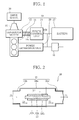
- Fig. 1 is a diagram showing one example of the schematic configuration of a drive apparatus 10.
- the drive apparatus 10 whose details will be given later has an engine 11 which is the power source of a vehicle, a generator motor 12 coupled to the output shaft of the engine 11 and a drive wheel 30, a battery 13, a power control unit 14, and a power generation unit 20 disposed in an exhaust gas passage 21 of the engine 11.
- the rotational shaft of the generator motor 12 has only to be coupled to the output shaft of the engine 11 via an arbitrary power transmission unit, and is not particularly limited as long as it is coupled to the drive wheel 30 via an arbitrary power transmission unit.
- the output shaft of the engine 11 is coupled to the rotational shaft of the generator motor 12 via a mechanical power transmission unit.
- the drive wheel 30 is coupled to the rotational shaft of the generator motor 12 via a transmission 31.
- the engine 11 drives the generator motor 12 when the generator motor 12 operates as a generator, and drives the drive wheel 30 via the transmission 31.
- the generator motor 12 when operating as a motor receives electric power supplied from the battery 13, and drives the drive wheel 30 together with the engine 11 via the transmission 31.
- the drive wheel 30 drives the generator motor 12, which operates as a generator, via the transmission 31.
- the power control unit 14 has a first port 14a connected to the generator motor 12, and a second port 14b connected to the battery 13. Therefore, the generator motor 12 when operating as a generator charges the battery 13 through the power control unit 14. The generator motor 12 when operating as a motor receives electric power supplied from the battery 13 through the power control unit 14. Further, the power generation unit 20 is electrically connected to the battery 13 to charge the battery 13, and, together with the battery 13, supplies electric power to the generator motor 12 when the generator motor 12 operates as a motor.
- a step-down unit 40 for supplying electric power to electrical devices which operate on a low voltage is needed ( Fig. 1).
- Fig. 1 exemplarily shows a plurality of drive wheels by one drive wheel 30, and the single drive wheel is not restrictive.
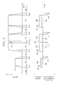
- the power generation unit 20 shown in Fig. 2 is a single cell type solid oxide fuel cell formed by disposing a solid oxide fuel cell 22 (hereinafter, referred to as fuel cell 22) in the exhaust gas passage 21.
- the exhaust gas passage 21 has a main passage 21a which accommodate the fuel cell 22 and in which a combusted exhaust gas 23 flows, an inlet part 21b which leads the combusted exhaust gas 23 exhausted from the engine 11 to the main passage 21a, and a discharge part 21c which discharge the combusted exhaust gas 23 having flowed through the main passage 21a.
- the fuel cell 22 has a solid oxide electrolyte 22a formed in, for example, a rectangular flat shape, and has an air electrode 22b formed on one surface of the solid oxide electrolyte 22a and a fuel electrode 22c formed on the other surface of the solid oxide electrolyte 22a.
- the solid oxide electrolyte 22a is formed of, for example, 8-mol-YSZ (yttria stabilized zirconia), 5-mol-YSZ, SDC (scandium doped ceria), GDC (gadolinium doped ceria), ScSZ (scandia stabilized zirconia) or the like.
- the air electrode 22b is formed of, for example, LSM (lanthanum strontium manganite), LSC (lanthanum strontium cobaltite) or the like.
- the fuel electrode 22c is formed of, for example, NiO+YSZ, NiO+SDC, NiO+GDC, LSCM (lanthanum strontium cobalt manganite), FeO 3 , or the like.
- the combusted exhaust gas 23 contains CHx, COx, Air, etc.
- the fuel cell 22 is heated to a temperature equal to or higher than a power generation start temperature.
- oxygen ions (O 2- ) are generated at the air electrode 22b from the air (Air) in the combusted exhaust gas 23.
- the oxygen ions generated this way move inside the solid oxide electrolyte 22a of the fuel cell 22 from the air electrode 22b to the fuel electrode 22c, and react with CHx or COx contained in the combusted exhaust gas 23 at the fuel electrode 22c to generate carbon (CO 2 ) or water (H 2 O).
- the air electrode 22b and fuel electrode 22c may be formed by depositing conductors on the respective surfaces of the solid oxide electrolyte 22a.
- the power generation unit 20 generates electric power using the combusted exhaust gas 23 in this manner.
- the power generation unit 20 discharge carbon dioxide or water (vapor) chemically converted from CHx or COx contained in the combusted exhaust gas 23 by the fuel cell 22. Therefore, the power generation unit 20 can purify the combusted exhaust gas 23.
- the power generation unit 20 may be configured to have a plurality of fuel cells 22 connected in serial parallel, so that the output voltage of the power generation unit 20 matches with the charge voltage of the battery 13. Alternatively, the power generation unit 20 may have its output boosted to the charge voltage of the battery 13 by means of an unshown voltage booster.
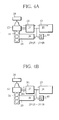
- Fig. 3 is a diagram illustrating the output current and drive current of the generator motor in each operational state of the vehicle having the drive apparatus 10 mounted therein.
- Fig. 4A, Fig. 4B , Fig. 4C and Fig. 4D are diagrams illustrating the currents of the generator motor 12, the battery 13, the power generation unit 20, etc. respectively at the time the vehicle decelerates, at the time the vehicle accelerates, at the time the vehicle runs, and at the time the vehicle is idling.
- J1 is the output current of the generator motor 12 when operating as a generator
- J2 is the drive current of the generator motor 12 when operating as a motor
- J3 is the charge current of the battery 13
- J4 is the discharge current of the battery 13
- J5 is the consumption current of the step-down unit 40
- J6 is the output current of the power generation unit 20.
- the power control unit 14 operates on the electric power supplied from the step-down unit 40. It is assumed that the current that flows into the first port 14a is entirely output from the second port 14b. Further, it is assumed that the current that flows into the second port 14b of the power control unit 14 is entirely output from the first port 14a. It is also assumed that the voltage drop between the first port 14a and the second port 14b is negligible.
- individual periods indicated by Da1 to Da4 are periods in which the vehicle having the drive apparatus 10 mounted therein is decelerating with the regenerative braking.
- the vehicle is decelerated from a speed V1 to a speed zero (stop).
- the vehicle is decelerated from a speed V3 to a speed V2.
- the vehicle is decelerated from the speed V3 to the speed zero (stop).
- the output current J1 of the generator motor 12 becomes smaller. That is, the maximum values of the output currents J1a and J1b become smaller than the maximum values of the output currents J1c and J1d as shown in Fig. 3 .
- individual periods indicated by Ac1 to Ac4 are periods in which the drive apparatus 10 is accelerating the vehicle.
- the drive apparatus 10 accelerates the vehicle from the speed zero (stop) to the speed V1.
- the drive apparatus 10 accelerates the vehicle from the speed zero (stop) to the speed V3.
- the drive apparatus 10 accelerates the vehicle from the speed V2 to the speed V3 at the acceleration period Ac3, and accelerates the vehicle from the speed zero (stop) to the speed V3 at the acceleration period Ac4.
- the drive apparatus needs to drive the drive wheel 30 with greater drive power.
- the drive apparatus 10 makes the generator motor 12 operate as a motor to supplement the output of the engine 11 in such a way that the engine 11 is operated at low fuel consumption and with less harmful substances in the combusted exhaust gas 23.
- the drive apparatus 10 selects the assist mode at the time of acceleration. As shown in Fig. 4B , therefore, the drive current J2 (drive currents J2a to J2d in Fig.
- the drive apparatus for a vehicle can reduce the power consumption of the battery 13 ( Figs. 3 and 4B ). That is, with the power consumption reduced in this manner, the battery 13 can drive the generator motor 12 operating as a motor for a longer time.
- the drive current J2 of the generator motor 12 operating as a motor becomes larger. That is, the maximum values of the drive currents J2b and J2d become larger than the maximum values of the drive currents J2a and J2c as shown in Fig. 3 .
- the situation in which the output current J1 of the generator motor 12 (generator) is let to flow to the battery 13 is defined as the charge mode.
- a period indicated by C1 is a period where the drive apparatus 10 causes the vehicle to run at a low speed.
- the vehicle secures the drive power to keep running by the output of the generator motor 12 operating as a motor in addition to the output of the engine 11.
- the drive apparatus 10 selects the assist mode.
- the power generation unit 20 supplies the consumption current J5 to the step-down unit 40 while covering the drive current J2 (J6a in Fig. 3 and J6a in Fig. 4C ) together with the battery 13. Therefore, the drive apparatus for a vehicle according to the present invention can reduce the power consumption of the battery 13.
- periods indicated by C2 to C4 are periods where the drive apparatus 10 causes the vehicle to run at an intermediate speed to a high speed.
- the output of the engine 11 is supplemented with the output of the generator motor 12 operating as a motor in order for the vehicle to secure larger drive power than the drive power at the low-speed running for keeping running.
- the drive apparatus 10 also selects the assist mode.
- the power generation unit 20 supplies the consumption current J5 to the step-down unit 40 while covering the drive current J2 (drive currents J2f to J2h in Fig. 3 ) together with the battery 13. Therefore, the drive apparatus 10 can reduce the power consumption of the battery 13.
- the drive apparatus 10 When the vehicle runs with inertia or the like even during the running period, however, the drive apparatus 10 need not select the assist mode. When the output of the engine 11 becomes greater than the output needed to drive the vehicle, such as when the vehicle runs on a downhill, the drive apparatus 10 can select the charge mode.
- periods indicated by Id1 to Id4 are periods where the vehicle has stopped and the drive apparatus 10 is idling.
- the engine 11 is operated at a relatively low speed. This makes it difficult to charge the battery 13 with the generator motor 12 operating as a generator.
- the drive apparatus 10 normally selects neither the charge mode nor the assist mode. That is, the first port 14a and the second port 14b of the power control unit 14 are electrically disconnected from each other. It is to be noted that the battery 13 can be charged with the power generation unit 20 even during the idling periods Id1 to Id4 if the consumption power of unshown electric devices mounted in the vehicle is reduced or the power generating performance of the power generation unit 20 is enhanced.
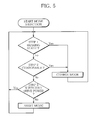
- Fig. 5 is a flowchart illustrating procedures of determining the operational state of the vehicle having the drive apparatus 10 mounted therein and selecting the charge mode or the assist mode.
- the power control unit 14 selects the mode.
- the drive apparatus 10 starts selecting the charge mode or the assist mode (start mode selection in Fig. 5 ).
- the power control unit 14 determines whether the vehicle is in a braking state (decelerating state) (step 1). When the power control unit 14 determines in step 1 that the vehicle is in the braking state (Yes in step 1), the power control unit 14 selects the charge mode to operate the generator motor 12 as a generator, feeds the output current J1 of the generator motor 12 (generator) to the second port 14b from the first port 14a to charge the battery 13, and returns the procedure to step 1. When the power control unit 14 determines in step 1 that the vehicle is not in the braking state (No in step 1), the power control unit 14 advances the procedure to step 2.
- the power control unit 14 determines in step 2 whether the engine 11 is generating an output equal to or greater than the output that is needed to drive the vehicle (i.e., whether it is chargeable). When the power control unit 14 determines in step 2 that it is chargeable (Yes in step 2), the power control unit 14 selects/keeps the charge mode, and then returns the procedure to step 1. When the power control unit 14 determines in step 2 that it is not chargeable (No in step 2), the power control unit 14 advances the procedure to step 3.
- the power control unit 14 determines whether driving of the vehicle is sufficiently achieved by the output of the engine 11 (i.e., whether the drive power is enough). When the power control unit 14 determines in step 3 that the drive power is enough (Yes in step 3), the power control unit 14 returns the procedure to step 1. When the power control unit 14 determines in step 3 that the drive power is not enough (No in step 3), the power control unit 14 selects the assist mode. Then, the power control unit 14 connects the battery 13 and the power generation unit 20 to the generator motor 12 to supply the drive current J2 to the generator motor 12 operating as a generator, and returns the procedure to step 1.
- the case where the power control unit 14 determines that the drive power is insufficient is when the vehicle speed drops even though, for example, the driver does not perform the deceleration manipulation.
- the power control unit 14 disconnects the electric connection between the first port 14a and the second port 14b.
- the power control unit 14 selects the charge mode or the assist mode as needed. That is, even if the power control unit 14 keeps the assist mode, the power generation unit 20 charges the battery 13. Therefore, the battery 13 can supply greater electric power to the generator motor 12 (motor), and achieve reduction in fuel consumption and reduction in the total amount of the combusted exhaust gas.
- Fig. 6 shows a modification of the power generation unit or a power generation unit 20A which includes a fuel cell 22A and heat generating device 26.
- the power generation unit 20B has a positive electrode 22d formed on the top surface of the air electrode 22b, and a negative electrode 22e formed on the top surface of the fuel electrode 22c.
- 24a is a P material electrode
- 25a is an N material electrode.
- the heat generating device 26 With an electric load (not shown) connected between the P material electrode 24a and N material electrode 25a, the heat generating device 26 generates electric power due to the Seebeck effect.
- the fuel cell 22A is accommodated in the main passage 21a of the exhaust gas passage 21 to constitute a single cell type solid oxide fuel cell, and generates electric power with the combusted exhaust gas used as a fuel gas.
- the heat generating device 26 is heated by the heat energy of the combusted exhaust gas and the reaction heat at the fuel electrode 22c of the fuel cell 22A to carry out the Seebeck-effect based power generation. That is, each of the fuel cell 22A and the heat generating device 26 of the power generation unit 20A generates electric power.
- the heat generating device 26 may contact the air electrode 22b of the fuel cell 22B through the electric insulating layer 27.
- the heat generating device 26 can generate electric power with the heat energy of the combusted exhaust gas even not in contact with the fuel cell 22A. Further, even if the power generation unit 20A comprises only the heat generating device 26, the power generation unit 20A can charge the battery 13. Therefore, the battery 13 can supply greater electric power to the generator motor 12 (motor), thus achieving reduction in fuel consumption and reduction in the total amount of the combusted exhaust gas.
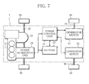
- the drive apparatus for a vehicle according to the present invention can be adapted to a four-wheel drive vehicle (4WD vehicle) as shown in Fig. 7 .
- 4WD vehicle four-wheel drive vehicle
- same reference numerals are given to the components which are the same as those of the embodiment and descriptions thereof are omitted.
- This four-wheel drive vehicle 1 has a couple of front wheels 38 rotated and driven by the engine 11 via the transmission 31 and a front-wheel drive shaft 32. Meanwhile, the four-wheel drive vehicle 1 has rear wheels 39 rotated and driven by the generator motors 12 via a rear-wheels drive shafts 41 respectively.
- each of the generator motors 12 receives electric power supplied from the battery 13 in assist mode, and each of the rear wheels 39 is driven by the corresponding generator motor 12 operating as a motor.
- the power control unit 14 operates in charge mode. At this time, the power control unit 14 stores the electric power generated by the generator motors 12, each of which is rotated and driven by the corresponding rear wheels 39 to operate as a generator, in the battery 13.
- the four-wheel drive vehicle 1 has the power generation unit 20 disposed in the exhaust gas passage 21 of the engine 11, and is configured to charge the battery 13 with electric power generated with a high-temperature exhaust gas flowing in the exhaust gas passage 21 (not shown in Fig. 7 ).
- the four-wheel drive vehicle (4WD vehicle) to which the drive apparatus for a vehicle according to the present invention is adapted can charge the battery 13 with electric power acquired from the combusted exhaust gas by the power generation unit 20 disposed in the exhaust gas passage of the engine 11 even when the generator motor 12 is not in a power generating state and cannot charge the battery 13, such as when the generator motor 12 operating as a motor is assisting the engine 11.
- the four-wheel drive vehicle to which the drive apparatus for a vehicle according to the present invention is adapted can supply greater electric power from the battery to the motor in assist mode, thus making it possible to achieve further reduction in fuel consumption and further reduction in the total amount of the combusted exhaust gas.
- the power generation unit 20 As a single cell type solid oxide fuel cell and/or a Seebeck-effect based heat generating device are/is used as the power generation unit 20, it is possible to achieve reduction in fuel consumption and reduction in the total amount of the combusted exhaust gas even with a simple configuration.
- This four-wheel drive vehicle may be configured in such a way that the front wheels 38 are rotated and driven by the generator motors 12, while the rear wheels 39 are rotated and driven by the engine 11.
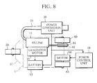
- the drive apparatus for a vehicle according to the present invention is adapted to a three-wheeled vehicle having a steered wheel 50 which sets the moving direction of the vehicle and a couple of drive wheels 60, 63 as shown in Fig. 8 .
- Fig. 8 same reference numerals are given to the components which are the same as those of the embodiment and descriptions thereof are omitted.
- the steered wheel 50 is interlocked with a steering bar 51 which is operated by the driver of the vehicle 1 to set the moving direction of the vehicle 1.
- the drive wheel 60 is driven by a gear 61 attached to the rotational shaft of the drive wheel 60 and a chain 62 which engages with the gear 61 to transmit the power generated by the engine 11.
- the other drive wheel 63 is coupled to a motor 64 which is connected to the drive shaft of the drive wheel 63 to rotate the drive wheel 60.
- the battery 13 is charged by a generator 18 which is coupled to the engine 11 and generates electric power due to the rotational drive power of the engine 11.
- the power generation unit 20 which generates electric power with the high-temperature exhaust gas flowing in the exhaust gas passage 21 and charges the battery 13 with the generated electric power is provided in the exhaust gas passage 21 of the engine 11. Therefore, the battery 13 is charged with the electric power generated by the power generation unit 20 besides the generator 18.
- the motor 64 is driven with the electric power stored in the battery 13 to rotate the drive wheel 63. At this time, the motor 64 which rotates and drives the drive wheel 63 is controlled by the power control unit 14 in such a way as to keep the same rotational speed as that of the other drive wheel 60 which is rotated and driven by the engine 11.
- the three-wheeled vehicle to which the drive apparatus for a vehicle according to the present invention is adapted allows the power generation unit 20 disposed in the exhaust gas passage 21 of the engine 11 to acquire electric power from the combusted exhaust gas and charge the battery 13, and allows the motor 64 to supplement the output of the engine 11, thus making it possible to achieve reduction in fuel consumption and reduction in the total amount of the combusted exhaust gas.
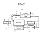
- the drive apparatus for a vehicle may be configured in such a way that as shown in Fig. 9 , the power generation unit 20 is attached to an ordinary two-wheeler and generates electric power with the high-temperature exhaust gas flowing in the exhaust gas passage 21 to charge the battery 13.
- the power generation unit 20 is attached to an ordinary two-wheeler and generates electric power with the high-temperature exhaust gas flowing in the exhaust gas passage 21 to charge the battery 13.
- the power generation unit 20 is attached to the exhaust gas passage 21 of the engine 11 in the two-wheeler.
- the drive apparatus may be configured so that the electric power of the generator 18 which is driven by the rotation of the engine 11 to generate electric power, and the electric power generated by the power generation unit 20 are stored in the battery 13.
- the drive apparatus for a vehicle according to the present invention which has such a configuration can acquire electric power from the combusted exhaust gas by means of the power generation unit 20 disposed in the exhaust gas passage 21 of the engine 11 to charge the battery 13, and can thus bring about practically significant effects, such as effective reuse of the energy which is exhausted as the combusted exhaust gas.
Landscapes
- Engineering & Computer Science (AREA)
- Transportation (AREA)
- Mechanical Engineering (AREA)
- Chemical & Material Sciences (AREA)
- Combustion & Propulsion (AREA)
- Power Engineering (AREA)
- Automation & Control Theory (AREA)
- Life Sciences & Earth Sciences (AREA)
- Sustainable Development (AREA)
- Sustainable Energy (AREA)
- Electric Propulsion And Braking For Vehicles (AREA)
- Hybrid Electric Vehicles (AREA)
Applications Claiming Priority (2)
| Application Number | Priority Date | Filing Date | Title |
|---|---|---|---|
| JP2006223215 | 2006-08-18 | ||
| PCT/JP2007/060704 WO2008020502A1 (fr) | 2006-08-18 | 2007-05-25 | Dispositif de propulsion de véhicule |
Publications (1)
| Publication Number | Publication Date |
|---|---|
| EP2052926A1 true EP2052926A1 (fr) | 2009-04-29 |
Family
ID=39082032
Family Applications (1)
| Application Number | Title | Priority Date | Filing Date |
|---|---|---|---|
| EP07744138A Withdrawn EP2052926A1 (fr) | 2006-08-18 | 2007-05-25 | Dispositif de propulsion de véhicule |
Country Status (7)
| Country | Link |
|---|---|
| US (1) | US8261862B2 (fr) |
| EP (1) | EP2052926A1 (fr) |
| JP (1) | JPWO2008020502A1 (fr) |
| KR (1) | KR101359252B1 (fr) |
| CN (1) | CN101528521B (fr) |
| CA (1) | CA2660347C (fr) |
| WO (1) | WO2008020502A1 (fr) |
Cited By (1)
| Publication number | Priority date | Publication date | Assignee | Title |
|---|---|---|---|---|
| WO2011125084A1 (fr) * | 2010-04-07 | 2011-10-13 | Università degli Studi di Salerno | Kit pour transformer un véhicule à moteur classique en véhicule hybride solaire et véhicule à moteur correspondant obtenu au moyen de ce kit |
Families Citing this family (14)
| Publication number | Priority date | Publication date | Assignee | Title |
|---|---|---|---|---|
| US8091677B2 (en) * | 2008-03-27 | 2012-01-10 | GM Global Technology Operations LLC | System and method of differentiating rotational speed and torque between wheels of a hybrid vehicle |
| US20090288893A1 (en) * | 2008-05-09 | 2009-11-26 | John C. Wyall | Controllerless electric drive system |
| US20100163321A1 (en) * | 2008-12-30 | 2010-07-01 | Goff Sean K | Power converter module for a battery-operated vehicle |
| WO2011001606A1 (fr) * | 2009-06-29 | 2011-01-06 | パナソニック株式会社 | Dispositif source d'énergie |
| US20110049892A1 (en) * | 2009-08-06 | 2011-03-03 | Jonathan Ross | System For Efficient Energy Generation |
| KR101124973B1 (ko) * | 2009-12-03 | 2012-03-27 | 현대자동차주식회사 | 하이브리드 차량의 모터 구동 시스템 및 이의 고장 제어 방법 |
| JP5624790B2 (ja) * | 2010-04-07 | 2014-11-12 | 株式会社アツミテック | 発電装置 |
| JP2012187961A (ja) * | 2011-03-09 | 2012-10-04 | Ygk:Kk | ハイブリッド車両 |
| EP2701933A4 (fr) * | 2011-04-25 | 2017-03-29 | High Gas Mileage, LLC | Véhicule hybride équipé de sous-systèmes d'énergie multiples |
| EP2639437A1 (fr) * | 2012-03-16 | 2013-09-18 | Perkins Engines Company Limited | Système de commande pour ensemble moteur |
| JP5977117B2 (ja) * | 2012-08-28 | 2016-08-24 | 住友理工株式会社 | 車両用防音カバー |
| US9162666B2 (en) * | 2013-03-15 | 2015-10-20 | GM Global Technology Operations LLC | Hybrid vehicle and method of braking by controlling an exhaust heat recovery device bypass valve on a hybrid vehicle |
| CN108357343A (zh) * | 2018-02-12 | 2018-08-03 | 潍柴动力股份有限公司 | 一种混合动力系统、混合动力系统的动力供应方法及车辆 |
| KR102519307B1 (ko) * | 2018-08-22 | 2023-04-07 | 제이텍 에너지 인코포레이티드 | 배기 가스 에너지 회수 변환기 |
Family Cites Families (16)
| Publication number | Priority date | Publication date | Assignee | Title |
|---|---|---|---|---|
| JPH05111101A (ja) * | 1991-10-17 | 1993-04-30 | Hino Motors Ltd | 車両の制動および補助駆動装置 |
| JPH1067243A (ja) * | 1996-08-29 | 1998-03-10 | Honda Motor Co Ltd | 車両における補助駆動装置 |
| JP2000243412A (ja) * | 1999-02-23 | 2000-09-08 | Ngk Spark Plug Co Ltd | 単室型固体電解質型燃料電池 |
| US6672415B1 (en) * | 1999-05-26 | 2004-01-06 | Toyota Jidosha Kabushiki Kaisha | Moving object with fuel cells incorporated therein and method of controlling the same |
| JP2002175824A (ja) * | 2000-12-08 | 2002-06-21 | Nissan Motor Co Ltd | 動力源システム及び固体酸化物燃料電池を用いた発電システムにおける固体酸化物燃料電池の暖機方法 |
| JP3960035B2 (ja) * | 2000-12-28 | 2007-08-15 | 三菱マテリアル株式会社 | ハイブリッド動力システム |
| US6401850B1 (en) * | 2001-03-14 | 2002-06-11 | New Venture Gear, Inc. | Electric drive axle for hybrid vehicle |
| JP4904568B2 (ja) * | 2001-03-21 | 2012-03-28 | 独立行政法人産業技術総合研究所 | 単室型固体電解質型燃料電池及びその製造方法 |
| FR2856198B1 (fr) * | 2003-06-16 | 2005-12-16 | Renault Sa | Cogeneration d'electricite par utilisation de l'effet seebeck a l'interieur d'une pile a combustible |
| DE602004006636T2 (de) * | 2003-09-25 | 2008-01-31 | Shell Internationale Research Maatschappij B.V. | Hilfskrafteinheit von festoxidbrennstoffzellen |
| JP2005151633A (ja) | 2003-11-12 | 2005-06-09 | Honda Motor Co Ltd | ハイブリッド車両 |
| JP2005166539A (ja) * | 2003-12-04 | 2005-06-23 | Toyota Motor Corp | 排気系に燃料電池を有する内燃機関 |
| WO2005063559A1 (fr) | 2003-12-25 | 2005-07-14 | Yamaha Hatsudoki Kabushiki Kaisha | Vehicule a moteur |
| CN100579840C (zh) * | 2004-11-11 | 2010-01-13 | 丰田自动车株式会社 | 动力输出装置及其控制方法和汽车 |
| DE602006012288D1 (de) * | 2005-04-04 | 2010-04-01 | Honda Motor Co Ltd | Stapelstruktur für Brennstoffzelle |
| US7870723B2 (en) * | 2006-02-14 | 2011-01-18 | Ford Global Technologies, Llc | System and method to operate fuel cell in the exhaust of an internal combustion engine |
-
2007
- 2007-05-25 EP EP07744138A patent/EP2052926A1/fr not_active Withdrawn
- 2007-05-25 CN CN2007800385657A patent/CN101528521B/zh active Active
- 2007-05-25 CA CA2660347A patent/CA2660347C/fr active Active
- 2007-05-25 US US12/377,997 patent/US8261862B2/en active Active
- 2007-05-25 KR KR1020097002761A patent/KR101359252B1/ko active Active
- 2007-05-25 WO PCT/JP2007/060704 patent/WO2008020502A1/fr not_active Ceased
- 2007-05-25 JP JP2008529822A patent/JPWO2008020502A1/ja active Pending
Non-Patent Citations (1)
| Title |
|---|
| See references of WO2008020502A1 * |
Cited By (1)
| Publication number | Priority date | Publication date | Assignee | Title |
|---|---|---|---|---|
| WO2011125084A1 (fr) * | 2010-04-07 | 2011-10-13 | Università degli Studi di Salerno | Kit pour transformer un véhicule à moteur classique en véhicule hybride solaire et véhicule à moteur correspondant obtenu au moyen de ce kit |
Also Published As
| Publication number | Publication date |
|---|---|
| KR101359252B1 (ko) | 2014-02-05 |
| CN101528521B (zh) | 2012-09-26 |
| WO2008020502A1 (fr) | 2008-02-21 |
| CA2660347A1 (fr) | 2008-02-21 |
| CN101528521A (zh) | 2009-09-09 |
| US20100243347A1 (en) | 2010-09-30 |
| US8261862B2 (en) | 2012-09-11 |
| KR20090060267A (ko) | 2009-06-11 |
| JPWO2008020502A1 (ja) | 2010-01-07 |
| CA2660347C (fr) | 2014-03-25 |
Similar Documents
| Publication | Publication Date | Title |
|---|---|---|
| CA2660347C (fr) | Dispositif de propulsion de vehicule | |
| US7147072B2 (en) | Method and apparatus for providing hybrid power in vehicle | |
| EP1385715B1 (fr) | Moteur electrique differentiel a conversion de couple variable | |
| Mohammadi | Design, analysis, and electrification of a solar-powered electric vehicle | |
| JP2011500418A (ja) | ハイブリッド伝動機構 | |
| US20220314809A1 (en) | System for adjusting regenerative torque according to state of charge of multiple batteries | |
| Fleming | Electric vehicle collaboration-toyota motor corporation and tesla motors [automotive electronics] | |
| JP2001258105A (ja) | ハイブリッド車両 | |
| CN201291753Y (zh) | 混合动力驱动系统 | |
| CN214874201U (zh) | 车辆 | |
| KR101242838B1 (ko) | 하이브리드 전기자동차의 듀얼모드 동력전달장치 | |
| CN115783209A (zh) | 一种船用混合动力系统及控制方法 | |
| KR20070082399A (ko) | 하이브리드 전기자동차의 듀얼모드 동력전달장치 | |
| CN201296160Y (zh) | 一种混合动力驱动系统 | |
| CN201437335U (zh) | 具有发电辅助模块的电动车辆 | |
| WO2021001717A1 (fr) | Génération électrique et gestion de véhicules électriques | |
| CN204936861U (zh) | 一种用于电动车辆的混合燃料电池储能装置 | |
| SE528921C2 (sv) | Energialstringssystem som utnyttjar en bränslecell | |
| CN221272660U (zh) | 车辆的动力系统及车辆 | |
| CN114735128B (zh) | 一种无电池辅助的复合固态储氢燃料电池电动自行车 | |
| TWI621551B (zh) | 燃料電池混合動力控制方法 | |
| CN2813353Y (zh) | 电力车的风力发电动力装置 | |
| Wangchuk et al. | From Design to Road: Development and Performance Analysis of an Electric Jeep | |
| KR100820403B1 (ko) | 하이브리드 차량용 모터 감속기 | |
| CN117183752A (zh) | 一种汽车动力系统、汽车 |
Legal Events
| Date | Code | Title | Description |
|---|---|---|---|
| PUAI | Public reference made under article 153(3) epc to a published international application that has entered the european phase |
Free format text: ORIGINAL CODE: 0009012 |
|
| 17P | Request for examination filed |
Effective date: 20090129 |
|
| AK | Designated contracting states |
Kind code of ref document: A1 Designated state(s): AT BE BG CH CY CZ DE DK EE ES FI FR GB GR HU IE IS IT LI LT LU LV MC MT NL PL PT RO SE SI SK TR |
|
| AX | Request for extension of the european patent |
Extension state: AL BA HR MK RS |
|
| DAX | Request for extension of the european patent (deleted) | ||
| RBV | Designated contracting states (corrected) |
Designated state(s): DE FR GB |
|
| STAA | Information on the status of an ep patent application or granted ep patent |
Free format text: STATUS: THE APPLICATION IS DEEMED TO BE WITHDRAWN |
|
| 18D | Application deemed to be withdrawn |
Effective date: 20161201 |