EP2052936A1 - System und Verfahren zum Assistieren bei der Fahrzeugabstandseinhaltung - Google Patents
System und Verfahren zum Assistieren bei der Fahrzeugabstandseinhaltung Download PDFInfo
- Publication number
- EP2052936A1 EP2052936A1 EP08167001A EP08167001A EP2052936A1 EP 2052936 A1 EP2052936 A1 EP 2052936A1 EP 08167001 A EP08167001 A EP 08167001A EP 08167001 A EP08167001 A EP 08167001A EP 2052936 A1 EP2052936 A1 EP 2052936A1
- Authority
- EP
- European Patent Office
- Prior art keywords
- reaction force
- operation reaction
- principal
- auxiliary
- headway distance
- Prior art date
- Legal status (The legal status is an assumption and is not a legal conclusion. Google has not performed a legal analysis and makes no representation as to the accuracy of the status listed.)
- Granted
Links
Images






Classifications
-
- B—PERFORMING OPERATIONS; TRANSPORTING
- B60—VEHICLES IN GENERAL
- B60W—CONJOINT CONTROL OF VEHICLE SUB-UNITS OF DIFFERENT TYPE OR DIFFERENT FUNCTION; CONTROL SYSTEMS SPECIALLY ADAPTED FOR HYBRID VEHICLES; ROAD VEHICLE DRIVE CONTROL SYSTEMS FOR PURPOSES NOT RELATED TO THE CONTROL OF A PARTICULAR SUB-UNIT
- B60W30/00—Purposes of road vehicle drive control systems not related to the control of a particular sub-unit, e.g. of systems using conjoint control of vehicle sub-units
- B60W30/14—Adaptive cruise control
- B60W30/16—Control of distance between vehicles, e.g. keeping a distance to preceding vehicle
-
- B—PERFORMING OPERATIONS; TRANSPORTING
- B60—VEHICLES IN GENERAL
- B60W—CONJOINT CONTROL OF VEHICLE SUB-UNITS OF DIFFERENT TYPE OR DIFFERENT FUNCTION; CONTROL SYSTEMS SPECIALLY ADAPTED FOR HYBRID VEHICLES; ROAD VEHICLE DRIVE CONTROL SYSTEMS FOR PURPOSES NOT RELATED TO THE CONTROL OF A PARTICULAR SUB-UNIT
- B60W50/00—Details of control systems for road vehicle drive control not related to the control of a particular sub-unit, e.g. process diagnostic or vehicle driver interfaces
- B60W50/08—Interaction between the driver and the control system
- B60W50/14—Means for informing the driver, warning the driver or prompting a driver intervention
- B60W50/16—Tactile feedback to the driver, e.g. vibration or force feedback to the driver on the steering wheel or the accelerator pedal
-
- B—PERFORMING OPERATIONS; TRANSPORTING
- B60—VEHICLES IN GENERAL
- B60K—ARRANGEMENT OR MOUNTING OF PROPULSION UNITS OR OF TRANSMISSIONS IN VEHICLES; ARRANGEMENT OR MOUNTING OF PLURAL DIVERSE PRIME-MOVERS IN VEHICLES; AUXILIARY DRIVES FOR VEHICLES; INSTRUMENTATION OR DASHBOARDS FOR VEHICLES; ARRANGEMENTS IN CONNECTION WITH COOLING, AIR INTAKE, GAS EXHAUST OR FUEL SUPPLY OF PROPULSION UNITS IN VEHICLES
- B60K26/00—Arrangement or mounting of propulsion-unit control devices in vehicles
- B60K26/02—Arrangement or mounting of propulsion-unit control devices in vehicles of initiating means or elements
- B60K26/021—Arrangement or mounting of propulsion-unit control devices in vehicles of initiating means or elements with means for providing feel, e.g. by changing pedal force characteristics
Definitions
- the present invention relates to a headway distance maintenance assisting system and method that assists the maintenance of vehicle headway distance. Aspects of the invention relate to a system, to a method, to a storage medium and to a vehicle.
- a headway distance maintenance assisting system that changes the reaction force to operation of the accelerator pedal according to the headway distance from the preceding vehicle is described in Japanese Kokai Patent Application No. Hei 10[1998]-166890 .
- the headway distance to the preceding vehicle is detected, and the reaction force acting on the accelerator pedal is increased in conjunction with a decrease in the headway distance from the preceding vehicle in order to arouse the driver's attention.
- control for changing the operation reaction force is not performed.
- Embodiments of the invention may provide a headway distance maintenance supporting system and method which solves the aforementioned problems.
- Other aims and advantages of the invention will become apparent from the following description, claims and drawings.
- a headway distance maintenance supporting system for a given vehicle comprising an obstacle detector for detecting status of obstacles present in front of the given vehicle, a controller configured for determining an operation reaction force to be generated in a driving operation equipment used by a driver of the given vehicle and an operation reaction force generator for generating the operation reaction force in the driving operation equipment based on the operation reaction force determined by the controller, wherein the controller is configured for controlling the operation reaction force generated by the operation reaction force generator in the driving operation equipment based on the status of a detected obstacle detected by the obstacle detector, wherein the operation reaction force determined by the controller comprises a principal operation reaction force and an auxiliary operation reaction force, the auxiliary operation reaction force being no greater than the principal operation reaction force, wherein the controller is configured for generating the auxiliary operation reaction force before a generation of the principal operation reaction force in the driving operation equipment.
- the controller is configured to control the operation reaction force to generate the principal operation reaction force when a distance from the given vehicle to the obstacle present in front of the given vehicle is detected to be less than a first headway distance threshold.
- the system may comprise an operation amount detector for detecting an operation amount of the driving operation equipment.
- the controller may be configured to control the auxiliary operation reaction force based on the operation amount of the driving operation equipment.
- the system may comprise a gradient detector for detecting a gradient of a road.
- the controller may be configured to control auxiliary operation reaction force based on the gradient.
- the controller is configured to compute arrival time until the principal operation reaction force is generated and determine the auxiliary operation reaction force based on the arrival time.
- the controller is configured to control the operation reaction force generator such that the operation reaction force is gradually increased to become the auxiliary operation reaction force when the auxiliary operation reaction force is generated in the driving operation equipment.
- the controller is configured to control the operation reaction force such that after the auxiliary operation reaction force is generated, the auxiliary operation reaction force is gradually decreased, and then the principal operation reaction force is generated in the driving operation equipment.
- the controller is configured to control the operation reaction force generator such that when the auxiliary operation reaction force is generated in the driving operation equipment, the operation reaction force is gradually increased at a prescribed variation rate to become the auxiliary operation reaction force, and then, the auxiliary operation reaction force is gradually decreased at a rate lower than the prescribed variation rate, followed by generation of the principal operation reaction force.
- the system may comprise an operation amount detector for detecting an operation amount of the driving operation equipment.
- the controller may be configured to determine the principal operation reaction force based on the operation amount of the driving operation equipment.
- the system may comprise a gradient detector for detecting a gradient of the road where the vehicle runs.
- the controller may be configured to control the principal operation reaction force based on the gradient.
- the controller configured to control the operation reaction force generator such that the operation reaction force generated by the operation reaction force generator is gradually increased to become the principal operation reaction force when the principal operation reaction force is generated in the driving operation equipment.
- a headway distance supporting system for a vehicle comprising an obstacle detecting means for detecting status of obstacles present in front of the given vehicle, a controlling means for determining an operation reaction force generated in a driving operation equipment used by a driver of the given vehicle and an operation reaction force generating means for generating the operation reaction force in the driving operation equipment based on the operation reaction force determined by the controlling means, wherein the controlling means is configured for controlling the operation reaction force generated by the operation reaction force generating means in the driving operation equipment based on the status of a detected obstacle detected by the obstacle detecting means, wherein the operation reaction force determined by the controlling means comprises a principal operation reaction force and an auxiliary operation reaction force, the auxiliary operation reaction force being no greater than the principal operation reaction force, and wherein the controlling means is configured for generating the auxiliary operation reaction force before a generation of the principal operation reaction force in the driving operation equipment.
- a headway distance maintenance supporting method for a given vehicle comprising detecting status of at least one obstacle present in front of the given vehicle, computing a principal operation reaction force and an auxiliary operation reaction force no greater than the principal operation reaction force generated in a driving operation equipment used by the driver of the given vehicle based on the status of a detected obstacle and generating the auxiliary operation reaction force before generating the principal operation reaction force in the driving operation equipment.
- a computer readable storage medium having stored data for headway distance maintenance support control for a given vehicle, wherein the computer readable storage medium stores a program for providing instructions for detecting status of obstacles present in front of the given vehicle, instructions for computing a principal operation reaction force and an auxiliary operation reaction force no greater than the principal operation reaction force generated in a driving operation equipment used by the driver of the given vehicle based on the status of a detected obstacle and instructing for generating the auxiliary operation reaction force before generating the principal operation reaction force in the driving operation equipment.
- a headway distance maintenance supporting system for a given vehicle may provide an improved support running of a given vehicle.
- a headway distance maintenance supporting system may include an obstacle detector for detecting status of obstacles present in front of the given vehicle, a controller configured for determining an operation reaction force to be generated in a driving operation equipment used by a driver of the given vehicle, and an operation reaction force generator for generating the operation reaction force in the driving operation equipment based on the operation reaction force determined by the controller.
- the controller is configured for controlling the operation reaction force generated by the operation reaction force generator in the driving operation equipment based on the status of a detected obstacle detected by the obstacle detector.
- the operation reaction force determined by the controller comprises a principal operation reaction force and an auxiliary operation reaction force, the auxiliary operation reaction force being no greater than the principal operation reaction force.
- the controller is configured for generating the auxiliary operation reaction force before a generation of the principal operation reaction force in the driving operation equipment.
- a headway distance maintenance supporting method for a given vehicle may include detecting status of at least one obstacle present in front of the given vehicle, computing a principal operation reaction force and an auxiliary operation reaction force no greater than said principal operation reaction force generated in a driving operation equipment used by the driver of the given vehicle based on the status of a detected obstacle, and generating the auxiliary operation reaction force before generating the principal operation reaction force in the driving operation equipment.
- a computer readable storage medium having stored data for headway distance maintenance supporting methods for a given vehicle, wherein the computer readable storage medium stores a program for providing instructions for detecting status of at least one of obstacle present in front of the given vehicle, instructions for computing a principal operation reaction force and an auxiliary operation reaction force no greater than said principal operation reaction force generated in a driving operation equipment used by the driver of the given vehicle based on the status of a detected obstacle, and instructions for generating the auxiliary operation reaction force before generating the principal operation reaction force in the driving operation equipment.
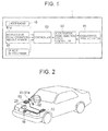
- Figure 1 is a system diagram showing the headway distance maintenance supporting system 1.
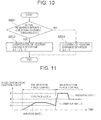
- Figure 2 is a diagram schematically showing a given vehicle or host vehicle that carries headway distance maintenance supporting system 1.
- laser radar 10 is attached to the front grille or front bumper of the given vehicle, and it scans horizontally with IR light pulses.
- Laser radar 10 measures the IR light pulse reflections from plural reflectors (usually the back end of the preceding vehicle) ahead of the given vehicle, and detects the headway distance for each of plural preceding vehicles and their directions from the arrival times of the reflected waves.
- the detected headway distances and their directions are output to controller 50.
- the direction of a forward object can be represented by its angle relative to the given vehicle.
- the forward region scanned by laser radar 10 is about ⁇ 6° with respect to the front of the given vehicle, and forward objects present within the range are detected.
- controller 50 may include a microcomputer, and it performs overall control of headway distance maintenance supporting system 1. Controller 50 detects the status of obstacles in the surroundings of the given vehicle from the given vehicle speed input from vehicle speed sensor 20 and the distance information input from laser radar 10. Based on the status of these obstacles, controller 50 computes first and second headway distance thresholds, to be explained later. In addition, controller 50 performs control corresponding to the first and second headway distance thresholds.
- headway distance maintenance supporting system 1 can appropriately assist the driving operations of the driver.
- controller 50 computes the first and second headway distance threshold from the status of the obstacles. Controller 50 then computes the target pedal reaction force with respect to the computed first and second headway distance thresholds. Then controller 50 outputs the computed target pedal reaction force to accelerator pedal reaction force controller 60.
- Accelerator pedal reaction force controller 60 controls the torque generated in accelerator pedal actuator 61 corresponding to the reaction force control amount output from controller 50.
- Accelerator pedal actuator 61 which is assembled with accelerator pedal 62, can generate any level of operation reaction force for accelerator pedal 62 according to the value of the instruction from accelerator pedal reaction force controller 60.
- the depressing force generated when the driver depresses accelerator pedal 62 which may be the driving operation equipment, can be controlled as desired.
- accelerator pedal actuator 61 Arranged in accelerator pedal actuator 61 are an output shaft, not shown in the figure, and sensor 61 a for detecting the rotational position of the output shaft.
- the output shaft is connected to a rotational shaft, not shown in the figure, of accelerator pedal 62.
- the rotational position of the output shaft detected by sensor 61 a uniquely corresponds to the operation amount of accelerator pedal 62. Consequently, sensor 61 a is used in the present embodiment as the accelerator pedal operation amount sensor that detects the operation amount of accelerator pedal 62.
- Figure 3 is a block diagram showing controller 50.
- Obstacle recognition device 51 computes the headway distance and relative speed with respect to the preceding vehicle (forward vehicle) based on the signal input from laser radar 10. Then the status of the obstacles ahead of the given vehicle is detected based on the headway distance and relative speed with respect to the preceding vehicle, as well as the given vehicle speed input from vehicle speed sensor 20.
- headway distance threshold computing device 52 computes the first and second headway distance thresholds.
- the accelerator pedal reaction force applied on the accelerator pedal is determined by target pedal reaction force determining device 53 based on the first and second headway distance thresholds and the headway distance.
- Figure 4 is a flow chart illustrating a process of headway distance maintenance supporting control performed in controller 50. This processing content is successively performed at prescribed intervals, such as 10 msec.
- the running status of the given vehicle is read in step S100.
- the running status refers to the information about the running status of the given vehicle, including the status of obstacles ahead of the given vehicle. More specifically, the headway distance and the direction of forward obstacles (preceding vehicles) detected by laser radar 10 and the speed of the given vehicle detected by vehicle speed sensor 20 are read.
- step S200 based on the running status data read and recognized in step S100, the status of the front obstacles is recognized.
- the relative position and movement direction/movement speed of the current obstacle with respect to the given vehicle are recognized from the relative position and movement direction/movement speed of the obstacle with respect to the given vehicle that was detected in the last processing cycle (i.e., previously detected) and stored in a memory, not shown in the figure, as well as the current running status data obtained in step S100.
- the obstacle with respect to travel of the given vehicle is recognized by how it is placed ahead of the given vehicle and how it moves relative to it.
- step S300 first headway distance threshold L* 1 with respect to the obstacle is computed.
- the processing performed in this case will be explained with reference to the flow chart shown in Figure 5 .
- step S301 headway distance threshold (steady-state term) L* h1 is computed.
- the headway distance threshold (steady-state term) is the item corresponding to when the preceding vehicle travels at a constant speed. In this example, it is set corresponding to relative speed Vr between the given vehicle speed VSP and the obstacle (preceding vehicle).
- L ⁇ * h ⁇ 1 f VSP ⁇ Vr
- step S302 the preceding vehicle speed Va is computed from the given vehicle's speed VSP and relative speed Vr, recognized in step S100 and step S200, using Equation (1).
- Va VSP + Vr
- step S303 the accelerator/deceleration rate ⁇ a of the preceding vehicle is computed.
- ⁇ a d Va / dt
- step S304 as a condition for computing and refreshing the headway distance threshold (transient term), judgment is made as to whether warning flag Fw, computed in step S400 and to be explained later, is set.
- step S305 a judgment is made on the deceleration of the preceding vehicle.
- judgment is made as to whether the deceleration of the preceding vehicle is lower than a prescribed level.
- ⁇ 0 represents the threshold for judging deceleration.
- ⁇ a of the preceding vehicle and deceleration judgment threshold ⁇ 0 the value for acceleration is positive, and for deceleration it is negative.
- step S306 when it is judged that the preceding vehicle has decelerated in step S305, the following equation is used to compute and refresh parameter Tr1 for the headway distance threshold (transient term).
- Tr ⁇ 1 L - L ⁇ * h ⁇ 1 / Vr
- Tr1 represents the margin distance, represented as a relative speed time coefficient, of actual headway distance L with respect to headway distance threshold (steady-state term) L*h1 at the time that the preceding vehicle started deceleration.
- step S308 headway distance (transient term) L* r1 is computed using the following equation.
- L ⁇ * r ⁇ 1 Tr ⁇ 1 ⁇ Vr
- first headway distance threshold L* 1 is computed.
- it is computed as the sum of headway distance threshold (steady-state term) L*h1 and headway distance (transient term) L* r1 according to the following equation.
- L ⁇ * 1 L ⁇ * h ⁇ 1 + L ⁇ * r ⁇ 1
- step S400 the warning flag is set/cleared.
- Second headway distance threshold L* 2 with reference to the obstacle is computed in step S500.
- second headway distance threshold L* 2 has a value larger than that of the first headway distance threshold L* 1 (L* 1 ⁇ L* 2 ).
- the processing to compute the second headway distance threshold performed in step S500 will be explained in more detail with reference to Figures 6-10 .
- step S500 The processing performed in step S500 is performed according to the flow chart shown in Figure 6 .
- step S51 the gradient of the road on which the given vehicle runs is estimated.
- air resistance F a and rolling resistance F r acting on the given vehicle can be computed using the following equations.
- F a ⁇ a ⁇ s v ⁇ VSP 2
- F r ⁇ r ⁇ M v ⁇ g
- ⁇ a represents the air resistance coefficient
- S v represents the frontal projected area of the given vehicle
- ⁇ r represents the rolling resistance coefficient
- M v represents the weight of the given vehicle
- g represents the acceleration due to gravity.
- the acceleration of the given vehicle is estimated from the driving shaft torque generated from engine torque and brake hydraulic pressure, as well as the air resistance and rolling resistance, and it is compared to the actual acceleration.
- gradient SLP of the road where the given vehicle runs can be estimated using the following Equation (11).
- SLP T w - T br - R w ⁇ F a + F r / M r ⁇ R w - s ⁇ VSP
- s is a Laplace operator
- R w is a coefficient for computing the gradient
- Second headway distance threshold L* 2 is computed in step S520.
- the processing for computing the second headway distance threshold performed in step S520 will be explained in more detail with reference to Figures 7-9 .
- step S520 The processing performed in step S520 is performed according to the flow chart shown in Figure 7 .
- preceding vehicle speed dependent reference distance L* h2 is computed from the map shown in Figure 8 . As shown in Figure 8 , the preceding vehicle dependent reference distance L* h2 is computed such that the engine torque output quantity with respect to the accelerator pedal depression amount is controlled from a greater distance when the preceding vehicle speed is higher.
- step S522 gradient dependent correction time T_slp is computed from the map shown in Figure 9 .
- the gradient dependent correction time when the gradient is positive, that is, when the given vehicle travels uphill, the gradient dependent correction time has a negative value.
- the gradient when the gradient is negative, that is, when the given vehicle travels downhill, it is set to be a positive value.
- the absolute value of the gradient dependent correction time is set larger.
- the absolute value of the gradient dependent correction time is fixed at a prescribed value.
- the preceding vehicle dependent reference distance computed in step S521 is corrected by multiplying relative speed Vr with respect to the obstacle by the gradient dependent correction time T_slp. The processing for correcting the preceding vehicle dependent reference distance will be explained later.
- Relative speed dependent correction distance L* r2 is computed in step S523.
- the following equation is used to compute relative speed dependent correction distance L* r2 from prescribed reference time T1 and gradient dependent correction time T_slp computed in step S522.
- L ⁇ * r ⁇ 2 T ⁇ 1 + T_slp ⁇ - Vr
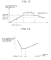
- step S530 the deviation of the headway distance is computed from actual headway distance L and second headway distance threshold L* 2 .
- step S530 The processing performed in step S530 is performed according to the flow chart shown in Figure 10 .
- step S531 If the judgment result in step S531 is NO, the process proceeds to step S533 and headway distance deviation ⁇ L 2 is cleared.
- auxiliary target accelerator pedal reaction force (auxiliary operation reaction force) Tp, to be explained later, is generated.
- the auxiliary operation reaction force is also called pre-reaction force.
- the degree of proximity is assumed to enable maintenance of the headway distance when accelerator operation is performed.
- the auxiliary operation reaction force is effected before generation of the principal operation reaction force, to be explained later.
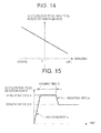
- Target accelerator pedal reaction force Tp is computed in step S600 shown in Figure 4 . Also, more specifically, target accelerator pedal reaction force Tp is generated as shown in Figure 12 .
- reaction force C and variation rate c are considered to be the reaction force value (reaction force value C) and variation rate that allow the driver to notice the reaction force in a state in which there is relatively significant latitude for motion, such that the headway distance is maintained while the driver performs accelerator operation, and holding time t2 is about 1 sec.
- variation rate d has a value smaller than variation rate c, and the value of reaction force D (reaction force value D) is smaller than that of reaction force value C, so that it is possible to reduce the reaction force while suppressing any uneasy feeling caused by releasing the reaction force.
- the accelerator operation amount corresponds to the conventionally used region.
- the driver may feel uneasy. Consequently, it is reduced to a level that causes no uneasy feeling.
- the larger the throttle opening the larger the reaction force values C, D.
- the driver will hardly notice the reaction force if it is small. Consequently, by increasing the reaction force value in this case, the driver can be aroused to notice the reaction force.
- Such a map is not limited to reaction force values C, D, but can also be adopted for variation rate c.
- the prescribed reaction force values C, D and the prescribed variation rate c can be changed according to the gradient of the road surface. As shown in Figure 14 , when the gradient has a positive value, that is, when the given vehicle climbs a slope, it is possible by reducing the reaction force to prevent an excessive accelerator pedal reaction force so that any uneasy feeling can be minimized. As explained above, the gradient is determined from Equation (11) in step S510.
- the prescribed reaction force values C, D and prescribed variation rate c can be changed according to the time of arrival at headway distance threshold L* 1 for generation of the principal operation reaction force. Please see the following (for computation of the arrival time and of the reaction force value).
- TTW2 represents the correction value corresponding to the arrival time. It has a larger value when the arrival time is shorter, and a smaller value when the arrival time is longer. By having a smaller value of TTW2 when the arrival time is longer, it is possible to use a smaller reaction force, to prevent excessive accelerator pedal reaction force and reduce any uneasy feeling.
- first headway distance threshold L* 1 when it is judged that the time until breaking of the computing condition of the principal operation reaction force (first headway distance threshold L* 1 ) is short, for example, when it is judged that the headway distance will break first headway distance threshold L* 1 after 1 sec, the principal operation reaction force alone may be computed. As a result, the principal operation reaction force can be efficiently transmitted to the driver.
- target accelerator pedal reaction force Tm is generated.
- the principal operation reaction force is also called the principal reaction force.
- Target accelerator pedal reaction force Tm is computed in step S700 shown in Figure 4 . More specifically, this target accelerator pedal reaction force Tm is generated as shown in Figure 15 .
- the principal operation reaction force is generated at a prescribed variation rate a until a prescribed reaction force value A is achieved.
- the accelerator pedal reaction force is decreased at a prescribed variation rate b until reaching prescribed reaction force value B.
- the reaction force value A is considered to be a value that enables the driver to easily notice the reaction force
- variation rate a is approximately the speed of shifting the foot to the brake pedal
- holding time t3 is set at about 0.5 sec.
- reaction force value A is set corresponding to the accelerator pedal operation amount, so that the smaller the accelerator pedal operation amount, the larger the reaction force value A.
- reaction force value A is set corresponding to the accelerator pedal operation amount, so that the smaller the accelerator pedal operation amount, the larger the reaction force value A.
- gain Ka is a value corresponding to the increased amount of depression of the accelerator pedal depression by the driver.
- the maximum value of gain Ka is set at 0.8, and the value decreases as the depression increment of the accelerator pedal by the driver (for example, the increase in the throttle opening with reference to the throttle opening at the time that application of the principal operation reaction force at a variation rate was started).
- the relationship between reaction force value B and the depression increment of the accelerator pedal is shown in Figure 16 .
- Final target accelerator pedal reaction force T is determined in step S800 and accelerator pedal reaction force controller 60 controls the reaction force generated in accelerator pedal 62.
- the final target accelerator pedal reaction force is obtained as the result of selecting the higher of auxiliary operation reaction force and principal operation reaction force, as shown in the following equation.
- T max Tp ⁇ Tm
- Headway distance maintenance supporting system 1 in Embodiment 1 realizes the following operation and effects.
- headway distance maintenance supporting system and method according to another embodiment (Embodiment 2) of the present invention will be explained with reference to Figures 17-21 .
- headway distance maintenance supporting system 1 of Embodiment 2 in addition, if the driver does not depress the accelerator pedal, control is performed to decelerate the given vehicle under prescribed conditions. This feature is different from Embodiment 1.
- the features that differ will be emphasized, and symbols that are the same as those used in Embodiment 1 will be adopted as is. The features not explained here are the same as those in Embodiment 1.
- Figure 17 is a system diagram showing the headway distance maintenance supporting system 1 according to another embodiment of the present invention (Embodiment 2).
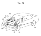
- Figure 18 is a diagram schematically showing a vehicle that carries headway distance maintenance supporting system 1.
- 92 represents the brake pedal
- 93 represents the braking force controller
- 94 represents the braking device such as a hydraulic brake provided at each wheel.
- Controller 50 computes the target deceleration rate based on second headway distance threshold L* 2 and the operation state of accelerator pedal 62. Also, controller 50 computes the target brake hydraulic pressure based on the computed target deceleration rate, and this is output to braking force controller 93. Braking force controller 93 generates a brake hydraulic pressure so that the target brake hydraulic pressure output from controller 50 is reached, and the hydraulic pressure for braking is fed to braking device 94. As a result, the given vehicle is decelerated at the target deceleration rate.
- Figure 19 is a block diagram showing controller 50 of the headway distance maintenance supporting system according to another embodiment of the present invention.
- Target deceleration rate computing device 56 computes the target deceleration rate generated for the given vehicle based on second headway distance threshold L* 2 computed by headway distance threshold computing device 52 and the status of accelerator operation by the driver judged by driver operation judgment device 54.
- Braking force control amount computing device 57 computes the target brake hydraulic pressure based on the target deceleration rate computed by target deceleration rate computing device 56 and the status of accelerator operation by the driver judged by driver operation judgment device 54.
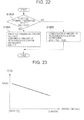
- Figure 20 is a flow chart illustrating a process of the headway distance maintenance supporting control performed by controller 50 in Embodiment 2. Unlike in Embodiment 1, the following processing steps are added: target deceleration rate computing process in step S900, and braking force control amount computing process in step S1000.
- step S901 judgment is made as to whether throttle opening Acc exceeds prescribed value Acc0. If the judgment result in step S901 is YES, the process proceeds to step S903, and accelerator operation flag Facc is set to 1. On the other hand, if the judgment result in step S901 is NO, the process proceeds to step S905, and accelerator operation flag Facc is cleared.
- accelerator operation judgment threshold Acc0 for judging whether the accelerator is in the fully closed state is set at a small value.
- step S907 target deceleration rate ⁇ * 2 is computed according to second headway distance threshold L* 2 and the accelerator operation performed by the driver judged in step S901.
- Kr2 represents the gain for computing the target deceleration rate generated in the given vehicle.
- ⁇ * 2 has a positive value in case of acceleration, and it has a negative value in case of deceleration.
- a variation limit of ⁇ * 2 may be set in target deceleration rate ⁇ * 2 2.
- step S1000 the braking force control amount is computed corresponding to second target deceleration rate ⁇ *2 computed in step S900.
- deceleration ⁇ *eng generated by the engine brake is subtracted from target deceleration rate ⁇ *2 to compute target deceleration rate ⁇ *brk generated by the brake (braking device).
- ⁇ *brk, ⁇ *eng take positive values in acceleration, and negative values in deceleration.
- target brake hydraulic pressure P* is computed.
- Kb represents the gain for converting the target deceleration rate to the target brake hydraulic pressure, and it is determined according to the various parameters of the given vehicle.
- Braking force controller 93 generates the brake hydraulic pressure so as to reach the target brake hydraulic pressure P*.
- the obstacle detecting means corresponds to laser radar 10 and its equivalents
- the operation reaction force generating means corresponds to accelerator pedal reaction force controller 60 and accelerator pedal actuator 61 and their equivalents
- the accelerator pedal operation amount detecting means corresponds to sensor 61 a and its equivalents.
- the control means corresponds to controller 50 and the control program executed by controller 50 and their equivalents.
Landscapes
- Engineering & Computer Science (AREA)
- Automation & Control Theory (AREA)
- Transportation (AREA)
- Mechanical Engineering (AREA)
- Human Computer Interaction (AREA)
- Control Of Driving Devices And Active Controlling Of Vehicle (AREA)
- Regulating Braking Force (AREA)
Applications Claiming Priority (2)
| Application Number | Priority Date | Filing Date | Title |
|---|---|---|---|
| JP2007275679 | 2007-10-23 | ||
| JP2008221320A JP5439766B2 (ja) | 2007-10-23 | 2008-08-29 | 車間維持支援装置および車間維持支援方法 |
Publications (2)
| Publication Number | Publication Date |
|---|---|
| EP2052936A1 true EP2052936A1 (de) | 2009-04-29 |
| EP2052936B1 EP2052936B1 (de) | 2012-02-29 |
Family
ID=40280854
Family Applications (1)
| Application Number | Title | Priority Date | Filing Date |
|---|---|---|---|
| EP08167001A Active EP2052936B1 (de) | 2007-10-23 | 2008-10-20 | System und Verfahren zum Assistieren bei der Fahrzeugabstandseinhaltung |
Country Status (2)
| Country | Link |
|---|---|
| US (1) | US8219311B2 (de) |
| EP (1) | EP2052936B1 (de) |
Cited By (1)
| Publication number | Priority date | Publication date | Assignee | Title |
|---|---|---|---|---|
| EP2529970A4 (de) * | 2010-01-28 | 2018-04-25 | Nissan Motor Co., Ltd | Vorrichtung zur steuerung der zum niederdrücken eines gaspedals nötigen kraft |
Families Citing this family (11)
| Publication number | Priority date | Publication date | Assignee | Title |
|---|---|---|---|---|
| JP5375557B2 (ja) * | 2009-03-27 | 2013-12-25 | 日産自動車株式会社 | 車両用アクセルペダル反力付与装置及びその方法 |
| JP5471856B2 (ja) * | 2010-06-07 | 2014-04-16 | 日産自動車株式会社 | アクセルペダル踏力制御装置及びアクセルペダル踏力制御方法 |
| JP5510173B2 (ja) * | 2010-08-11 | 2014-06-04 | トヨタ自動車株式会社 | 車両制御装置 |
| JP5964609B2 (ja) * | 2012-02-23 | 2016-08-03 | 株式会社日本自動車部品総合研究所 | 車両用追従制御装置 |
| US9454905B2 (en) * | 2013-04-29 | 2016-09-27 | Global Foundries Inc. | Safe distance determination |
| JP6033197B2 (ja) * | 2013-10-08 | 2016-11-30 | 株式会社ホンダロック | 反力出力装置 |
| US9993191B2 (en) * | 2015-12-29 | 2018-06-12 | Thunder Power New Energy Vehicle Development Company Limited | Onboard system for mitigating distraction risk |
| CN107010065A (zh) * | 2016-09-23 | 2017-08-04 | 阿里巴巴集团控股有限公司 | 汽车辅助方法、装置及系统 |
| US20180354362A1 (en) * | 2017-06-09 | 2018-12-13 | Honda Motor Co., Ltd. | Vehicle accelerator pedal force system, and methods of use and manufacture thereof |
| JP7081263B2 (ja) * | 2018-03-29 | 2022-06-07 | マツダ株式会社 | 車両用制御装置 |
| WO2020135812A1 (en) | 2018-12-29 | 2020-07-02 | Shanghai United Imaging Intelligence Co., Ltd. | Systems and methods for ossification center detection and bone age assessment |
Citations (10)
| Publication number | Priority date | Publication date | Assignee | Title |
|---|---|---|---|---|
| EP1375280A2 (de) * | 2002-06-20 | 2004-01-02 | Nissan Motor Co., Ltd. | System und Verfahren zur Fahrhilfe |
| EP1400435A2 (de) * | 2002-09-18 | 2004-03-24 | Nissan Motor Co., Ltd. | Fahrzeug-Fahr-Assistenz-System |
| JP3573134B2 (ja) | 2002-02-25 | 2004-10-06 | 日産自動車株式会社 | 車両用運転操作補助装置 |
| US20040225424A1 (en) * | 2001-08-23 | 2004-11-11 | Nissan Motor Co., Ltd. | Driving assist system |
| WO2005084992A1 (en) * | 2004-03-03 | 2005-09-15 | Nissan Motor Co., Ltd. | Method and system for assisting a driver of a vehicle operating a vehicle traveling on a road |
| JP3778165B2 (ja) | 2002-12-06 | 2006-05-24 | 日産自動車株式会社 | 車両用走行制御装置 |
| EP1707462A1 (de) * | 2005-03-31 | 2006-10-04 | Hitachi, Ltd. | Pedalsystem für Kraftfahrzeug |
| EP1749724A2 (de) * | 2005-08-05 | 2007-02-07 | Nissan Motor Company Limited | Fahrassistenzsystem für ein Kraftfahrzeug |
| JP2007275679A (ja) | 2007-07-31 | 2007-10-25 | Sankyo Kk | 遊技機の基板収納ボックス |
| JP2008221320A (ja) | 2007-03-15 | 2008-09-25 | Nissin Kogyo Co Ltd | 鋳造装置 |
Family Cites Families (13)
| Publication number | Priority date | Publication date | Assignee | Title |
|---|---|---|---|---|
| DE19607788B4 (de) * | 1996-03-01 | 2009-05-07 | Robert Bosch Gmbh | Verfahren und Vorrichtung zur Steuerung der Annäherung eines Fahrzeugs an ein Hindernis |
| JPH10166890A (ja) | 1996-12-04 | 1998-06-23 | Suzuki Motor Corp | 警報装置 |
| EP1349131B1 (de) * | 2000-11-24 | 2006-01-18 | Aisin Seiki Kabushiki Kaisha | Fahrzeugkollisionsverhinderungsvorrichtung |
| JP3613264B2 (ja) * | 2002-06-18 | 2005-01-26 | 日産自動車株式会社 | 車両用運転操作補助装置 |
| US7155341B2 (en) * | 2002-06-21 | 2006-12-26 | Nissan Motor Co., Ltd. | System and method for informing vehicle environment |
| JP3620532B2 (ja) * | 2002-11-12 | 2005-02-16 | 日産自動車株式会社 | 車両用報知装置 |
| JP4290455B2 (ja) * | 2003-03-28 | 2009-07-08 | 日産自動車株式会社 | 車両用制動制御装置 |
| JP2007022238A (ja) * | 2005-07-14 | 2007-02-01 | Nissan Motor Co Ltd | 車両用運転操作補助装置および車両用運転操作補助装置を備えた車両 |
| ATE390313T1 (de) * | 2005-10-19 | 2008-04-15 | Fiat Ricerche | Haptische anzeige umfassend ein gaspedal für ein kraftfahrzeug |
| JP4788611B2 (ja) * | 2006-03-10 | 2011-10-05 | 日産自動車株式会社 | 車間維持支援装置および車間維持支援方法 |
| JP5077733B2 (ja) * | 2006-03-31 | 2012-11-21 | いすゞ自動車株式会社 | 車両の制動装置 |
| US7745966B2 (en) * | 2006-12-11 | 2010-06-29 | Hansen Corporation | Method and device for an actuator motor including an air-actuated brake device |
| CN101896384A (zh) * | 2007-12-12 | 2010-11-24 | 沃尔沃拉斯特瓦格纳公司 | 用于控制基础制动器的系统和方法 |
-
2008
- 2008-10-20 EP EP08167001A patent/EP2052936B1/de active Active
- 2008-10-22 US US12/256,164 patent/US8219311B2/en active Active
Patent Citations (10)
| Publication number | Priority date | Publication date | Assignee | Title |
|---|---|---|---|---|
| US20040225424A1 (en) * | 2001-08-23 | 2004-11-11 | Nissan Motor Co., Ltd. | Driving assist system |
| JP3573134B2 (ja) | 2002-02-25 | 2004-10-06 | 日産自動車株式会社 | 車両用運転操作補助装置 |
| EP1375280A2 (de) * | 2002-06-20 | 2004-01-02 | Nissan Motor Co., Ltd. | System und Verfahren zur Fahrhilfe |
| EP1400435A2 (de) * | 2002-09-18 | 2004-03-24 | Nissan Motor Co., Ltd. | Fahrzeug-Fahr-Assistenz-System |
| JP3778165B2 (ja) | 2002-12-06 | 2006-05-24 | 日産自動車株式会社 | 車両用走行制御装置 |
| WO2005084992A1 (en) * | 2004-03-03 | 2005-09-15 | Nissan Motor Co., Ltd. | Method and system for assisting a driver of a vehicle operating a vehicle traveling on a road |
| EP1707462A1 (de) * | 2005-03-31 | 2006-10-04 | Hitachi, Ltd. | Pedalsystem für Kraftfahrzeug |
| EP1749724A2 (de) * | 2005-08-05 | 2007-02-07 | Nissan Motor Company Limited | Fahrassistenzsystem für ein Kraftfahrzeug |
| JP2008221320A (ja) | 2007-03-15 | 2008-09-25 | Nissin Kogyo Co Ltd | 鋳造装置 |
| JP2007275679A (ja) | 2007-07-31 | 2007-10-25 | Sankyo Kk | 遊技機の基板収納ボックス |
Cited By (1)
| Publication number | Priority date | Publication date | Assignee | Title |
|---|---|---|---|---|
| EP2529970A4 (de) * | 2010-01-28 | 2018-04-25 | Nissan Motor Co., Ltd | Vorrichtung zur steuerung der zum niederdrücken eines gaspedals nötigen kraft |
Also Published As
| Publication number | Publication date |
|---|---|
| US8219311B2 (en) | 2012-07-10 |
| US20090105953A1 (en) | 2009-04-23 |
| EP2052936B1 (de) | 2012-02-29 |
Similar Documents
| Publication | Publication Date | Title |
|---|---|---|
| EP2052936B1 (de) | System und Verfahren zum Assistieren bei der Fahrzeugabstandseinhaltung | |
| KR100921585B1 (ko) | 차간 유지 지원 장치 | |
| JP4788611B2 (ja) | 車間維持支援装置および車間維持支援方法 | |
| CN103707885B (zh) | 车间保持支持装置以及车间保持支持方法 | |
| US7395144B2 (en) | Brake assisting control system using a distance index | |
| CN101032956B (zh) | 车间距离保持辅助系统及方法 | |
| US6687595B2 (en) | Adaptive cruise control system for vehicle | |
| EP1127728B1 (de) | Verfahren zur Verwaltung von unverträglichen Drehmomentanforderungen in einem Geschwindigkeitsregelungssystem | |
| JP2010247815A (ja) | 車両用アクセルペダル反力付与装置及びその方法 | |
| EP4056437B1 (de) | Antriebssteuerungsvorrichtung für fahrzeug | |
| US8121772B2 (en) | Headway distance maintenance supporting device and method | |
| JP5439766B2 (ja) | 車間維持支援装置および車間維持支援方法 | |
| JP4821382B2 (ja) | 車間維持支援装置 | |
| JP3666345B2 (ja) | 自動走行制御装置 | |
| JP3458663B2 (ja) | 車両駆動力制御装置 | |
| JP4915112B2 (ja) | 車間維持支援装置および車間維持支援方法 |
Legal Events
| Date | Code | Title | Description |
|---|---|---|---|
| PUAI | Public reference made under article 153(3) epc to a published international application that has entered the european phase |
Free format text: ORIGINAL CODE: 0009012 |
|
| AK | Designated contracting states |
Kind code of ref document: A1 Designated state(s): AT BE BG CH CY CZ DE DK EE ES FI FR GB GR HR HU IE IS IT LI LT LU LV MC MT NL NO PL PT RO SE SI SK TR |
|
| AX | Request for extension of the european patent |
Extension state: AL BA MK RS |
|
| 17P | Request for examination filed |
Effective date: 20091005 |
|
| 17Q | First examination report despatched |
Effective date: 20091103 |
|
| AKX | Designation fees paid |
Designated state(s): DE FR GB |
|
| GRAP | Despatch of communication of intention to grant a patent |
Free format text: ORIGINAL CODE: EPIDOSNIGR1 |
|
| GRAS | Grant fee paid |
Free format text: ORIGINAL CODE: EPIDOSNIGR3 |
|
| GRAA | (expected) grant |
Free format text: ORIGINAL CODE: 0009210 |
|
| AK | Designated contracting states |
Kind code of ref document: B1 Designated state(s): DE FR GB |
|
| REG | Reference to a national code |
Ref country code: GB Ref legal event code: FG4D |
|
| REG | Reference to a national code |
Ref country code: DE Ref legal event code: R096 Ref document number: 602008013730 Country of ref document: DE Effective date: 20120426 |
|
| PLBE | No opposition filed within time limit |
Free format text: ORIGINAL CODE: 0009261 |
|
| STAA | Information on the status of an ep patent application or granted ep patent |
Free format text: STATUS: NO OPPOSITION FILED WITHIN TIME LIMIT |
|
| 26N | No opposition filed |
Effective date: 20121130 |
|
| REG | Reference to a national code |
Ref country code: DE Ref legal event code: R097 Ref document number: 602008013730 Country of ref document: DE Effective date: 20121130 |
|
| REG | Reference to a national code |
Ref country code: FR Ref legal event code: PLFP Year of fee payment: 9 |
|
| REG | Reference to a national code |
Ref country code: FR Ref legal event code: PLFP Year of fee payment: 10 |
|
| REG | Reference to a national code |
Ref country code: FR Ref legal event code: PLFP Year of fee payment: 11 |
|
| REG | Reference to a national code |
Ref country code: DE Ref legal event code: R084 Ref document number: 602008013730 Country of ref document: DE |
|
| REG | Reference to a national code |
Ref country code: GB Ref legal event code: 746 Effective date: 20230922 |
|
| PGFP | Annual fee paid to national office [announced via postgrant information from national office to epo] |
Ref country code: GB Payment date: 20250923 Year of fee payment: 18 |
|
| PGFP | Annual fee paid to national office [announced via postgrant information from national office to epo] |
Ref country code: FR Payment date: 20250924 Year of fee payment: 18 |
|
| PGFP | Annual fee paid to national office [announced via postgrant information from national office to epo] |
Ref country code: DE Payment date: 20250923 Year of fee payment: 18 |