EP2052942B1 - Vorrichtung und Verfahren zur Steuerung und/oder Überwachung einer Schrankenanlage - Google Patents
Vorrichtung und Verfahren zur Steuerung und/oder Überwachung einer Schrankenanlage Download PDFInfo
- Publication number
- EP2052942B1 EP2052942B1 EP07119295A EP07119295A EP2052942B1 EP 2052942 B1 EP2052942 B1 EP 2052942B1 EP 07119295 A EP07119295 A EP 07119295A EP 07119295 A EP07119295 A EP 07119295A EP 2052942 B1 EP2052942 B1 EP 2052942B1
- Authority
- EP
- European Patent Office
- Prior art keywords
- barrier
- drive motor
- energy
- energy store
- barrier arm
- Prior art date
- Legal status (The legal status is an assumption and is not a legal conclusion. Google has not performed a legal analysis and makes no representation as to the accuracy of the status listed.)
- Revoked
Links
- 230000004888 barrier function Effects 0.000 title claims abstract description 153
- 238000000034 method Methods 0.000 title claims abstract description 15
- 238000012544 monitoring process Methods 0.000 claims description 16
- 238000004146 energy storage Methods 0.000 abstract description 41
- 239000003990 capacitor Substances 0.000 abstract description 2
- 230000008901 benefit Effects 0.000 description 11
- 230000007246 mechanism Effects 0.000 description 5
- 230000005540 biological transmission Effects 0.000 description 4
- 230000008859 change Effects 0.000 description 3
- 238000010276 construction Methods 0.000 description 2
- 230000007547 defect Effects 0.000 description 2
- 238000001514 detection method Methods 0.000 description 2
- 230000001771 impaired effect Effects 0.000 description 2
- 238000012423 maintenance Methods 0.000 description 2
- 239000000463 material Substances 0.000 description 2
- 230000001681 protective effect Effects 0.000 description 2
- 230000006978 adaptation Effects 0.000 description 1
- 238000005452 bending Methods 0.000 description 1
- 230000001419 dependent effect Effects 0.000 description 1
- 238000010586 diagram Methods 0.000 description 1
- 238000010494 dissociation reaction Methods 0.000 description 1
- 230000005593 dissociations Effects 0.000 description 1
- 238000009434 installation Methods 0.000 description 1
- 238000009413 insulation Methods 0.000 description 1
- 230000003993 interaction Effects 0.000 description 1
- 150000002500 ions Chemical class 0.000 description 1
- 238000002955 isolation Methods 0.000 description 1
- 239000011244 liquid electrolyte Substances 0.000 description 1
- 239000007787 solid Substances 0.000 description 1
- 239000000725 suspension Substances 0.000 description 1
Images




Classifications
-
- B—PERFORMING OPERATIONS; TRANSPORTING
- B61—RAILWAYS
- B61L—GUIDING RAILWAY TRAFFIC; ENSURING THE SAFETY OF RAILWAY TRAFFIC
- B61L29/00—Safety means for rail/road crossing traffic
- B61L29/08—Operation of gates; Combined operation of gates and signals
-
- E—FIXED CONSTRUCTIONS
- E01—CONSTRUCTION OF ROADS, RAILWAYS, OR BRIDGES
- E01F—ADDITIONAL WORK, SUCH AS EQUIPPING ROADS OR THE CONSTRUCTION OF PLATFORMS, HELICOPTER LANDING STAGES, SIGNS, SNOW FENCES, OR THE LIKE
- E01F13/00—Arrangements for obstructing or restricting traffic, e.g. gates, barricades ; Preventing passage of vehicles of selected category or dimensions
- E01F13/04—Arrangements for obstructing or restricting traffic, e.g. gates, barricades ; Preventing passage of vehicles of selected category or dimensions movable to allow or prevent passage
- E01F13/06—Arrangements for obstructing or restricting traffic, e.g. gates, barricades ; Preventing passage of vehicles of selected category or dimensions movable to allow or prevent passage by swinging into open position about a vertical or horizontal axis parallel to the road direction, i.e. swinging gates
Definitions
- This invention relates to an apparatus and a method for controlling and / or monitoring a barrier system, which barrier system comprises a pivotable barrier arm and a drive motor, by means of the drive motor of the barrier arm between a passive position and an active position is pivotally.
- the present invention relates to such a device, or such a method for controlling and / or monitoring a barrier system, in which a secure and reliable closure or opening of the barrier in emergency situations is ensured at any time, and in which minimizes the energy and material consumption become.
- Barriers are mechanical devices by means of which traffic routes can be blocked.
- barriers at the border crossings are used to prevent unauthorized transits.
- barriers, often in conjunction with a control mechanism are used where the entry or exit of vehicles or persons is to be controlled (such as in car parks and similar facilities).
- a barrier usually comprises one or more so-called barrier arms, ie transverse rods, which can be pivoted by a drive mechanism between the open and closed positions.
- the barrier arm is often supported in the closed position by a support post or similar device.
- some barriers also have a so-called suspension (Schkriechschutz) or a safety gate (Übersteigschutz).
- the barrier arm can be designed either as a solid rod or as an articulated arm, whereby the barriers in tight Space (eg in the underground parking garages) can be used.
- barrier systems An important aspect in the realization of barrier systems is the safe opening or closing of the barrier in extraordinary situations, for example in the event of a power failure or in the event of a major control failure. It is of course important from the safety standpoint that the barrier in such situations occupies the position which guarantees a minimal endangering of human lives and material goods.
- this safety position can vary depending on the type or area of application of the barrier. For example, in the case of a parking garage barrier, it is desirable that it occupies the open position in an exceptional situation. In this way it can be guaranteed that, for example, in a fire or other disaster the parked cars are not prevented from leaving.
- the situation is different at railroad or border crossings, where the barrier has to be brought into the closed position in the event of a fault, so that possible collisions with approaching trains or unauthorized border crossings are prevented.
- Conventional barrier systems basically use either mechanical elements (such as springs) or hydraulic means to secure a barrier return to the emergency position.
- mechanical elements such as springs
- hydraulic means to secure a barrier return to the emergency position.
- these conventional means have the disadvantage that they are susceptible to defects to a relatively high degree.
- the regular drive and this emergency drive ie the return in emergency situations
- the conventional barrier systems usually require relatively high electrical voltages in order to be able to be driven correctly at all.
- the power lines leading to the barrier systems must be specially insulated and secured so that the risk of accidents can be minimized. If the supply voltage is reduced, also increases the power consumption in such conventional systems. Not least, therefore, the energy supply lines in the conventional barrier systems must have a relatively large cross-section, so that the electrical energy required by the engine can actually be made available at any time.
- the device for controlling and / or monitoring a barrier system which barrier system comprises a pivotable barrier arm and a drive motor, wherein by means of the drive motor of the barrier arm between a passive position and an active position is pivotally, a chargeable energy storage for supplying energy to the drive motor and at least one control module, wherein the energy storage means of an external power supply is chargeable, and wherein by means of the control module, the direction of the energy flow from the external power supply to the energy storage and / or energy storage is controllable to the drive motor.
- the advantage of this invention is, in particular, that in the barrier system an energy storage device for supplying energy to the drive motor is provided in such a way that the energy required for the operation of the motor is present at any time directly on site.
- the control module by means of the control module, the current direction can be easily controlled, so that in particular the energy storage can be loaded in any position.
- the energy storage can now be charged directly, without the barrier system taken apart, or that the energy storage must be physically replaced.
- the external power supply a sufficient energy supply can always be guaranteed for the energy storage device, which always ensures that there is at least enough energy in the energy storage device to safely bring the barrier into the emergency position in the event of a power failure or other problem.
- the inventive control module the necessary balance between Energy storage (ie, charging) and energy use (ie, engine operation) can be found in a simple and very efficient way.
- the drive motor is a DC motor.
- DC motors basically have very good properties (for example, good controllability, good starting behavior, etc.), which qualify them particularly well for use in a barrier system.
- these DC motors have the advantage that the direction (or rotation) change can be easily made by the voltage reversal.
- the use of a DC motor in combination with the inventive control module allows, for example, the switching of the movement of the barrier arm from the passive position to the active position and vice versa, without additional elements and means.
- the external voltage supply is a DC protective extra-low voltage (SELV).
- SELV DC protective extra-low voltage
- SELV is common in the art and refers to the English term "Safety Extra Low Voltage”. From a safety extra-low voltage one speaks at very small electrical voltages, which offer special protection against electric shock due to their low height and the isolation from circuits with higher voltages. In this case, the voltage is so small that electrical currents in the human body normally remain without consequences.
- This embodiment variant has the advantage, among other things, that generally harmless and safe voltage lines can be used for the voltage supply of the energy store and the entire system (or the barrier system). Therefore, no special insulation measures are needed, so that the entire system can be built cheaper. In addition, much less powerful lines are needed for the lower voltages, so that the cross-section of the supply lines can be kept very small.
- the energy store is designed as a supercapacitor.
- the supercapacitors also called double-layer capacitors
- the supercapacitors are electronic components with a very high capacity (in some cases several thousand F), which is based in principle on the dissociation of ions in the liquid electrolyte.
- This embodiment variant has the particular advantage that, thanks to a supercapacitor, DC currents with very high current intensities can be provided relatively quickly.
- the energy can be stored in the supercapacitor, which can be supplied very quickly to the drive motor of the barrier system, so that even in emergency situations a very fast opening or closing of the barrier is guaranteed. Thanks to the very high capacity, these currents are quite sufficient to realize the movement of the barrier arm in a required quality.
- the energy storage is designed as a battery and / or an accumulator.
- the advantage of this embodiment is the very reliable operation of a battery or a rechargeable battery. Batteries and accumulators are also universally applicable and require a relatively low maintenance. Also, a battery or a rechargeable battery can be taken out relatively easily and replaced by a new element, which can often be of great advantage, in particular in rear-end collisions (where drivers drive into the barriers). Last but not least, the batteries or accumulators are capable of supplying electrical energy for a relatively long time. Finally, the energy density of batteries or accumulators is very high, which favors the construction of lighter systems.
- control module comprises at least one switch by means of which the energy flow to the energy store and / or from the energy store to the drive motor can be controlled.
- This embodiment variant has, inter alia, the advantage that the energy flow can be controlled very precisely.
- the switches can be used to ensure that the switching between the energy storage state (ie, charging of the energy storage device) and the plant operating state (ie movement of the barrier arm) can be efficiently controlled.
- the switches can be used to control the correct direction of rotation of the drive motor.
- the at least one switch can be actuated by at least one remote control.
- the advantage of this embodiment lies in the fact that the switchover between the various operating states (charging energy storage, moving the barrier arm from the passive to the active position, moving the barrier arm from the active to the passive position) not only on site but also from a remote location Place can be performed. Thus, no personnel on site must be engaged for the control or the monitoring of the barrier system, without the safety or operability of the barrier system would suffer. Thus, the operating costs of such a barrier system compared to other conventional barrier systems can be significantly reduced again.
- At least one sensor is provided for position detection of the barrier arm, by means of which sensor the energy flow to the energy store and / or from the energy store to the drive motor can be controlled.
- the advantage of this embodiment is, in particular, that the control or monitoring of the barrier system can be completely automated. Thanks to such a sensor, the position of the barrier arm can be detected, so that the barrier system can be controlled based on this information.
- a sensor can detect that the barrier arm has reached the desired position (e.g., the active position) and automatically change the barrier's operating mode from "move" to "stop".
- a plurality of sensors can also be provided which, in interaction with the other elements of the device according to the invention, enable optimum detection and thus precise and reliable control and / or monitoring of the barrier system.
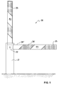
- FIG. 1 schematically a barrier system 20 is illustrated.
- the barrier system 20 basically consists of a barrier arm 25, which is pivotally mounted on a support post 21.
- the support post 21 is mostly fixed in the ground, although such implementations are conceivable in which the support post is attached, for example, to a side wall.
- barrier systems 20 are conceivable, which have no support post, but in which the barrier arm 25 is otherwise held exactly in the desired height.
- special fluorescent markers 26 ', 26 "are often attached to the barrier arm 25 (often in the combination of red-white or black-yellow), which are intended to help improve the visibility of the barrier barrier 20.
- the barrier arm 25 can (as in FIG. 1 shown) are pivoted in particular about a pivot point 22 on the support post 21 between a lying position P1 and an upright position P2.
- the barrier arm 25 in the lying position P1 obstructs the passage for the cars or persons, while this passage is possible at the barrier arm 25 in the upright position P2.
- the barrier arm 25 In the position P1, the barrier arm 25 is mostly passive, that is without any help from the drive mechanism, while a drive force has to be applied for the movement and holding of the barrier arm 25 in the upright position P2. So the lying position P1 becomes too as the "passive" position, while for the upright position P2 partially the name "active" position is used.
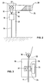
- FIG. 2 schematically shows the structure of the support post 21 of the barrier system 20 according to an embodiment of the present invention.
- the reference numeral 22 in FIG. 2 refers to a pivot point about which the barrier arm 25 can rotate by means of the drive motor 30 between the passive position P1 (as shown) and the active position P2 (not shown).
- this drive motor 30 can therefore rotate in two different directions, wherein in a first direction of rotation movement of the barrier arm 25 is reached from the position P1 to the position P2, while the drive motor 30 for moving the barrier arm 25 from the position P2 back in must move the position P1 in an opposite second direction.
- the drive motor 30 is therefore advantageously an electric motor, for example a DC electric motor.
- the drive motor 30 is also an AC electric motor or is realized in a completely different way.
- the drive motor 30 could basically be replaced by a hydraulic or similar drive.
- the reference numeral 31 refers to a rotation transmission member, by means of which the movement of the drive motor 30 is transmitted to the barrier arm 25.
- the rotation transmission element 31 is designed as a drive belt, which rests at one end on the rotary part of the drive motor 30, and at the other end on a gripping wheel 23 of the barrier arm 25.
- the movement (ie, rotation) of the drive motor 30 is transmitted to the barrier arm 25 via the rotation transmitting member 31 so that the barrier arm 25 is pivoted in the desired direction.
- the barrier arm 25 for example, from the passive position P1 (eg lying) in the active position P2 (eg standing) are pivoted.
- the passive position P1 eg lying
- the active position P2 eg standing
- FIG. 2 a device 10 for controlling and / or monitoring the inventive barrier system 20 shown.
- This device 10 is connected via a control line 32 to the drive motor 30, so that the drive motor 30 can be controlled or monitored by the device 10.
- the control line 32 is advantageously an electrical line, but according to the various embodiments of the drive motor 30 may also be designed as a hydraulic or another line.
- a voltage supply 11 is shown, by means of which the electrical energy of the device 10 can be supplied.
- FIG. 3 A detailed schematic view of the device 10 for controlling and / or monitoring a barrier system 20 according to one of the embodiments of the invention is shown in FIG. 3 illustrated.
- the reference numeral 30 refers again to the drive motor, the reference numeral 32 to the control line for controlling the drive motor 30 through the device 10, and the reference numeral 11 to the voltage supply for supplying electrical energy to the device 10th
- the device 10 in FIG. 3 includes an energy storage 35, by means of which energy to the drive motor 30 can be supplied.
- this energy store 35 in the device 10 may be an energy store for the electrical energy that is required for the operation of the electric motor 30. If the drive motor 30 is designed as a DC motor, then the energy storage device 35 will be a direct current storage device in this case.
- this energy store 35 can be embodied in particular as a battery (or a rechargeable battery) or else as a supercapacitor.
- a battery or a rechargeable battery
- the energy storage 35 is connected in this embodiment of the invention via a connecting line 34 with a control module 36 of the device 10. Thanks to this control module 36 can on the one hand the direction of the energy flow between the energy storage 35 and the Drive motor 30, and on the other hand, the energy flow to the energy storage 35 are controlled from the outside.
- the energy storage 35 may be rechargeable in particular. By the chargeability of the energy storage 35 can be prevented that the energy storage 35 must be replaced constantly. On the other hand, it is made possible by an energy store 35 that the barrier system 20 can be used without a constant supply of voltage being present.
- the control module 36 includes a switch 37, so that the direction of the energy flow can be controlled thanks to the changeover of this switch 37.
- the switch 37 is schematically illustrated by a rotary switch which can be switched between three different positions.
- the switch position "+” the current flows from the energy store 35 to the drive motor 30 in the first direction, which may correspond, for example, to the movement of the barrier arm 25 from the passive position P1 to the active position P2.
- this current flow is reversed, so that the electric current from the energy store 35 to the drive motor 30 now flows in the other direction, which the movement of the barrier arm 25 from the active position P2 to the passive position P1 corresponds.
- the rotary switch 37 also has a position "0". When the switch 37 is set in this position, the flow of current between the energy storage 35 and the drive motor 30 is interrupted. In addition, the current flow to the energy storage 35 from the outside, that is started via the voltage supply 11. In this way, the energy storage 35 can be charged when the energy from the energy storage 35 is not needed just to move the barrier arm 25 in one or the other direction.
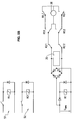
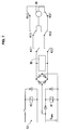
- FIG. 4 an electronic scheme of a possible implementation of the device 10 for controlling and / or monitoring a barrier system 20 according to an embodiment of the present invention is shown.
- the reference numeral 30 refers to the drive motor, and the reference numeral 35 to the energy storage.
- the energy store may in particular be a battery or an accumulator, or a supercapacitor. In any case, the energy storage 35 is fully charged after a certain time, so that the applied voltage can be turned off afterwards.
- the external voltage supply 11 can be realized as a DC protective extra-low voltage (SELV).
- the device 10 also includes a number of switches K1.1, K1.2, K2.1, K2.2, K3.1 and K4.1, which can be operated either individually or together.
- these switches K1.1, K1.2, K2.1, K2.2, K3.1 and K4.1 can be actuated by the remote controls 51, 52, 53.
- at least one sensor for detecting the position of the barrier arm 25 can be provided by means of which the energy flow from the outside to the energy storage 35 and the energy flow from the energy storage 35 to the drive motor 30 can be controlled. These sensors can either directly or via the remote controls 51, 52, 53 can influence the flow of energy.
- the three illustrated remote controls 51, 52, 53 electronic circuits each comprising a relay K4, K3, K2, by means of which the switches K4.1, K3.1, K2.1 and K2.2 can be switched.
- a relay K1 is also provided on the voltage supply line to the energy storage device 35, by means of which the switches K1.1 and K1.2 can be switched.
- other implementations of the remote controls 51, 52, 53 or the voltage supply line are also possible possible possible. The more precise operation of the device 10 is shown in the following figures.
- FIG. 5A the electronics scheme is off FIG. 4 shown at the time when the barrier arm 25 is pivoted from the passive position P1 to the active position P2.
- a first voltage U is actively applied to the voltage supply (ie to the voltage supply line 11).
- the movement of the barrier arm 25 is caused to the active position P2.
- the remote controls 51 and 52 and their respective relays K4 and K3 are used.
- the circuit in the remote control 51 must be closed, so that the switch K4.1 is actuated by the relay K4, while the circuit remains open in the remote control 52.
- the switch K3.1 remains in its original position.
- the switches K2.1 and K2.2 are also in their original position. It can now be in FIG. 5A be clearly seen that the electric current via the two switches K2.1 and K1.1 to the drive motor 30 and then via the two switches K3.1, K1.2 and K2.2 can flow back to the starting point.
- the drive motor 30 rotates in a predetermined direction, which is transmitted via the rotation transmission member 31 to the barrier arm 25.
- the barrier arm 25 moves from the passive position P1 to the active position P2 until the active position P2 is reached.
- the circuit in the remote control 52 can be activated, for example, by means of a special sensor or in another way, whereby the switch K3.1 switches over and the current flow to the drive motor 30 is interrupted by the relay K3.
- the circuit in the remote control 51 is opened, whereby the switch K4.1 returns to its original position.
- This situation of the electronic scheme is in FIG. 5B shown.
- this active position P2 may correspond to the opened barrier (the barrier arm 25 of FIG Barrier system 20 above), but of course other possibilities are conceivable.
- the electric current flows from the energy store 35 via the switches K2.1, K1.1 and K4.1 to the drive motor 30 and then back to the starting point via the switches K1.2 and K2.2.
- the drive motor 30 rotates in the other predetermined direction, which in turn is transmitted to the barrier arm 25 via the rotation transmission member 31.
- the barrier arm 25 now moves from the active position P2 to the passive position P1 until the passive position P1 has again been reached.
- the circuit in the remote control 51 is activated, for example by a special sensor or otherwise, whereby, thanks to the relay K4, to switch the switch K4.1 and to interrupt the flow of current to the drive motor 30 comes.
- the circuit in the remote control 52 will open, allowing the switch K3.1 to return to its original position.
- FIG. 6B This situation of the electronic scheme is in FIG. 6B shown. Now the input voltage U can remain passive , but also switched off, without the barrier arm 25 would move from the passive position P1.
- the energy store 35 can be charged as long as either the voltage U active or the voltage U passively remain applied to the voltage supply line 11. It also basically does not matter which of the two voltages is applied, since the energy store 35 can also be designed in particular so that it can be charged equally by the two voltages.
- the remote control 53 represents a so-called "active shutdown".
- This active shutdown represents an additional safety function, which is used in the inventive device 10 for controlling and / or monitoring a barrier system 20 in order to increase the overall safety of the system 20.
- the circuit of the remote control 52 is closed with the relay K2.
- the closing of the circuit in the remote control 52 causes the switching of the switches K2.1 and K2.2 by the relay K2, whereby the drive motor 30 is disconnected from the energy storage 35.
- either the first voltage U active or the second voltage U can be applied passively to the voltage supply (ie to the voltage supply line 11) without the drive motor 30 starting to move.
- this active shutdown can ensure that the barrier arm 25 remains in the intended position (P1 or P2) in any situation, even if the applied voltage (U active or U passive ) should change or fail completely for some reason.
- barrier systems 20 in which there is no active to move the barrier arm 25 from the active position P2 to the passive position P1 Force is needed because the barrier arm 25 can return to its original position due to its own weight.
- the present invention also relates to this type of barrier system 20, but of course some minor adjustments are necessary.
- these and other similar adaptations are entirely comprehensible to a person skilled in the art without inventive step and are likewise encompassed by the scope of protection of the following patent claims.
Landscapes
- Engineering & Computer Science (AREA)
- Mechanical Engineering (AREA)
- Architecture (AREA)
- Civil Engineering (AREA)
- Structural Engineering (AREA)
- Charge And Discharge Circuits For Batteries Or The Like (AREA)
- Manipulator (AREA)
- Burglar Alarm Systems (AREA)
Priority Applications (3)
| Application Number | Priority Date | Filing Date | Title |
|---|---|---|---|
| PL07119295T PL2052942T3 (pl) | 2007-10-25 | 2007-10-25 | Urządzenie i sposób sterowania i/lub monitorowania instalacji barierowej |
| EP07119295A EP2052942B1 (de) | 2007-10-25 | 2007-10-25 | Vorrichtung und Verfahren zur Steuerung und/oder Überwachung einer Schrankenanlage |
| AT07119295T ATE526222T1 (de) | 2007-10-25 | 2007-10-25 | Vorrichtung und verfahren zur steuerung und/oder überwachung einer schrankenanlage |
Applications Claiming Priority (1)
| Application Number | Priority Date | Filing Date | Title |
|---|---|---|---|
| EP07119295A EP2052942B1 (de) | 2007-10-25 | 2007-10-25 | Vorrichtung und Verfahren zur Steuerung und/oder Überwachung einer Schrankenanlage |
Publications (2)
| Publication Number | Publication Date |
|---|---|
| EP2052942A1 EP2052942A1 (de) | 2009-04-29 |
| EP2052942B1 true EP2052942B1 (de) | 2011-09-28 |
Family
ID=39267752
Family Applications (1)
| Application Number | Title | Priority Date | Filing Date |
|---|---|---|---|
| EP07119295A Revoked EP2052942B1 (de) | 2007-10-25 | 2007-10-25 | Vorrichtung und Verfahren zur Steuerung und/oder Überwachung einer Schrankenanlage |
Country Status (3)
| Country | Link |
|---|---|
| EP (1) | EP2052942B1 (pl) |
| AT (1) | ATE526222T1 (pl) |
| PL (1) | PL2052942T3 (pl) |
Cited By (1)
| Publication number | Priority date | Publication date | Assignee | Title |
|---|---|---|---|---|
| US20230159064A1 (en) * | 2020-04-22 | 2023-05-25 | Innova Patent Gmbh | Cableway Station Having a Safety Barrier |
Families Citing this family (3)
| Publication number | Priority date | Publication date | Assignee | Title |
|---|---|---|---|---|
| IT1396053B1 (it) * | 2009-10-01 | 2012-11-09 | Balfour Beatty Rail Spa | Apparecchiatura di alimentazione e telecontrollo asupercondensatore per apparecchiatureelettromeccaniche di linee metrotramviarie efiloviarie |
| US11667311B2 (en) * | 2020-06-11 | 2023-06-06 | Siemens Mobility, Inc. | Supercapacitor power supply for a gate crossing mechanism |
| PL446405A1 (pl) * | 2023-10-17 | 2025-01-20 | Politechnika Świętokrzyska | Układ sterowania bezszczotkowym silnikiem prądu stałego do napędu rogatkowego |
Family Cites Families (7)
| Publication number | Priority date | Publication date | Assignee | Title |
|---|---|---|---|---|
| US5852350A (en) * | 1997-09-08 | 1998-12-22 | Safetran Systems Corporation | Railroad crossing gate control system including a separate maintenance relay |
| US6307339B1 (en) * | 1998-11-23 | 2001-10-23 | Western-Cullen-Hayes, Inc. | Bi-directionally dynamically braked gate crossing mechanism controller |
| DE10007132A1 (de) * | 2000-02-17 | 2001-09-06 | Schreck Mieves Gmbh | Straßenbahnschrankenanlage |
| US20020027510A1 (en) * | 2000-04-28 | 2002-03-07 | Jones Dale G. | Apparatus and method for traffic signal flash mode during power outages |
| US6618993B2 (en) * | 2001-03-19 | 2003-09-16 | Thomas J. Burke | Railroad grade crossing assembly |
| US7302320B2 (en) * | 2001-12-21 | 2007-11-27 | Oshkosh Truck Corporation | Failure mode operation for an electric vehicle |
| FR2880365B1 (fr) * | 2005-01-05 | 2007-03-16 | Alain Fouassier | Dispositif autonome de type barriere automatique, permettant de reserver l'acces a certaines voies ou zones protegees |
-
2007
- 2007-10-25 PL PL07119295T patent/PL2052942T3/pl unknown
- 2007-10-25 EP EP07119295A patent/EP2052942B1/de not_active Revoked
- 2007-10-25 AT AT07119295T patent/ATE526222T1/de active
Cited By (1)
| Publication number | Priority date | Publication date | Assignee | Title |
|---|---|---|---|---|
| US20230159064A1 (en) * | 2020-04-22 | 2023-05-25 | Innova Patent Gmbh | Cableway Station Having a Safety Barrier |
Also Published As
| Publication number | Publication date |
|---|---|
| PL2052942T3 (pl) | 2012-02-29 |
| ATE526222T1 (de) | 2011-10-15 |
| EP2052942A1 (de) | 2009-04-29 |
Similar Documents
| Publication | Publication Date | Title |
|---|---|---|
| EP2496509B1 (de) | Aufzug | |
| EP2887535B1 (de) | Antriebs- und Steuersystem für Hubtore | |
| EP2440432B1 (de) | Schaltungsanordung und steuerverfahren zur spannungsstützung eines bordnetzes eines fahrzeugs | |
| DE10129966A1 (de) | Türöffner für eine Schiebetür | |
| EP0663505B1 (de) | Automatische Schiebetür mit mindestens einem Flügel | |
| EP2052942B1 (de) | Vorrichtung und Verfahren zur Steuerung und/oder Überwachung einer Schrankenanlage | |
| DE102015102924A1 (de) | Feststellanordnung für eine Tür | |
| DE102005059246B4 (de) | Kurzzeit-Spannungsversorgung | |
| DE4235138C2 (de) | Einrichtung zur Schutzentladung von Gleichspannungskondensatoren in einer Stromrichteranlage | |
| EP4058650A1 (de) | Hydraulischer torantrieb für ein hubtor und hubtor aufweisend den hydraulischen torantrieb sowie verfahren zum betreiben des hydraulischen torantriebs | |
| DE102018008812A1 (de) | Ausfallsicherer batteriebetriebener Freilauftürschließer | |
| AT516914A1 (de) | Verfahren und Einrichtung zur Zentrierung einer ungekuppelten Mittelpufferkupplung | |
| EP0829613A2 (de) | Bremsvorrichtung für einen Rauchschutzvorhang o. dgl. | |
| DE102008048337B4 (de) | Hubladebühne und Verfahren zum Betrieb einer Hubladebühne | |
| DE102017004719A1 (de) | Vorrichtung für einen gesicherten Bereich in einem Aufzugschacht | |
| DE202016008782U1 (de) | Förderwagen mit autonomer Energieversorgung für Notsituationen | |
| EP3130736B1 (de) | Set, umfassend eine automatiktür, wie beispielweise eine schiebetür, eine drehtür oder dergleichen, und eine signaleinrichtung, beispeilsweise eine brandmeldezentrale oder einen rauchmelder | |
| EP2946649B1 (de) | Sicherung einer schliessstellung eines schliessorgans einer einhausung | |
| DE202013011874U1 (de) | Ausfallsichere Antriebseinheit | |
| DE202007014541U1 (de) | Fensterscheibenantrieb | |
| EP3575531B1 (de) | Anlage zur feststellung eines tür- oder fensterflügels | |
| DE102017219950A1 (de) | Feststellanlage | |
| DE202006020317U1 (de) | Motorisch angetriebenes Tor sowie Torantriebsvorrichtung und Kommunikationseinrichtung hierfür | |
| DE20118594U1 (de) | Schnelllauftor mit Notöffnung | |
| DE20103868U1 (de) | Ladebordwandsystem für Fahrzeuge |
Legal Events
| Date | Code | Title | Description |
|---|---|---|---|
| PUAI | Public reference made under article 153(3) epc to a published international application that has entered the european phase |
Free format text: ORIGINAL CODE: 0009012 |
|
| AK | Designated contracting states |
Kind code of ref document: A1 Designated state(s): AT BE BG CH CY CZ DE DK EE ES FI FR GB GR HU IE IS IT LI LT LU LV MC MT NL PL PT RO SE SI SK TR |
|
| AX | Request for extension of the european patent |
Extension state: AL BA HR MK RS |
|
| 17P | Request for examination filed |
Effective date: 20091024 |
|
| 17Q | First examination report despatched |
Effective date: 20091120 |
|
| AKX | Designation fees paid |
Designated state(s): AT BE BG CH CY CZ DE DK EE ES FI FR GB GR HU IE IS IT LI LT LU LV MC MT NL PL PT RO SE SI SK TR |
|
| RAP1 | Party data changed (applicant data changed or rights of an application transferred) |
Owner name: SCHWEIZER ELECTRONIC AG |
|
| GRAP | Despatch of communication of intention to grant a patent |
Free format text: ORIGINAL CODE: EPIDOSNIGR1 |
|
| GRAS | Grant fee paid |
Free format text: ORIGINAL CODE: EPIDOSNIGR3 |
|
| GRAA | (expected) grant |
Free format text: ORIGINAL CODE: 0009210 |
|
| AK | Designated contracting states |
Kind code of ref document: B1 Designated state(s): AT BE BG CH CY CZ DE DK EE ES FI FR GB GR HU IE IS IT LI LT LU LV MC MT NL PL PT RO SE SI SK TR |
|
| REG | Reference to a national code |
Ref country code: GB Ref legal event code: FG4D Free format text: NOT ENGLISH |
|
| REG | Reference to a national code |
Ref country code: CH Ref legal event code: EP |
|
| REG | Reference to a national code |
Ref country code: IE Ref legal event code: FG4D |
|
| REG | Reference to a national code |
Ref country code: CH Ref legal event code: NV Representative=s name: BOVARD AG |
|
| REG | Reference to a national code |
Ref country code: DE Ref legal event code: R096 Ref document number: 502007008250 Country of ref document: DE Effective date: 20111215 |
|
| REG | Reference to a national code |
Ref country code: NL Ref legal event code: VDEP Effective date: 20110928 |
|
| PG25 | Lapsed in a contracting state [announced via postgrant information from national office to epo] |
Ref country code: SE Free format text: LAPSE BECAUSE OF FAILURE TO SUBMIT A TRANSLATION OF THE DESCRIPTION OR TO PAY THE FEE WITHIN THE PRESCRIBED TIME-LIMIT Effective date: 20110928 Ref country code: LT Free format text: LAPSE BECAUSE OF FAILURE TO SUBMIT A TRANSLATION OF THE DESCRIPTION OR TO PAY THE FEE WITHIN THE PRESCRIBED TIME-LIMIT Effective date: 20110928 Ref country code: FI Free format text: LAPSE BECAUSE OF FAILURE TO SUBMIT A TRANSLATION OF THE DESCRIPTION OR TO PAY THE FEE WITHIN THE PRESCRIBED TIME-LIMIT Effective date: 20110928 |
|
| LTIE | Lt: invalidation of european patent or patent extension |
Effective date: 20110928 |
|
| PG25 | Lapsed in a contracting state [announced via postgrant information from national office to epo] |
Ref country code: CY Free format text: LAPSE BECAUSE OF FAILURE TO SUBMIT A TRANSLATION OF THE DESCRIPTION OR TO PAY THE FEE WITHIN THE PRESCRIBED TIME-LIMIT Effective date: 20110928 Ref country code: GR Free format text: LAPSE BECAUSE OF FAILURE TO SUBMIT A TRANSLATION OF THE DESCRIPTION OR TO PAY THE FEE WITHIN THE PRESCRIBED TIME-LIMIT Effective date: 20111229 Ref country code: SI Free format text: LAPSE BECAUSE OF FAILURE TO SUBMIT A TRANSLATION OF THE DESCRIPTION OR TO PAY THE FEE WITHIN THE PRESCRIBED TIME-LIMIT Effective date: 20110928 Ref country code: LV Free format text: LAPSE BECAUSE OF FAILURE TO SUBMIT A TRANSLATION OF THE DESCRIPTION OR TO PAY THE FEE WITHIN THE PRESCRIBED TIME-LIMIT Effective date: 20110928 |
|
| REG | Reference to a national code |
Ref country code: PL Ref legal event code: T3 |
|
| REG | Reference to a national code |
Ref country code: IE Ref legal event code: FD4D |
|
| BERE | Be: lapsed |
Owner name: SCHWEIZER ELECTRONIC A.G. Effective date: 20111031 |
|
| PG25 | Lapsed in a contracting state [announced via postgrant information from national office to epo] |
Ref country code: CZ Free format text: LAPSE BECAUSE OF FAILURE TO SUBMIT A TRANSLATION OF THE DESCRIPTION OR TO PAY THE FEE WITHIN THE PRESCRIBED TIME-LIMIT Effective date: 20110928 Ref country code: IS Free format text: LAPSE BECAUSE OF FAILURE TO SUBMIT A TRANSLATION OF THE DESCRIPTION OR TO PAY THE FEE WITHIN THE PRESCRIBED TIME-LIMIT Effective date: 20120128 Ref country code: SK Free format text: LAPSE BECAUSE OF FAILURE TO SUBMIT A TRANSLATION OF THE DESCRIPTION OR TO PAY THE FEE WITHIN THE PRESCRIBED TIME-LIMIT Effective date: 20110928 |
|
| PG25 | Lapsed in a contracting state [announced via postgrant information from national office to epo] |
Ref country code: MC Free format text: LAPSE BECAUSE OF NON-PAYMENT OF DUE FEES Effective date: 20111031 Ref country code: PT Free format text: LAPSE BECAUSE OF FAILURE TO SUBMIT A TRANSLATION OF THE DESCRIPTION OR TO PAY THE FEE WITHIN THE PRESCRIBED TIME-LIMIT Effective date: 20120130 Ref country code: EE Free format text: LAPSE BECAUSE OF FAILURE TO SUBMIT A TRANSLATION OF THE DESCRIPTION OR TO PAY THE FEE WITHIN THE PRESCRIBED TIME-LIMIT Effective date: 20110928 Ref country code: NL Free format text: LAPSE BECAUSE OF FAILURE TO SUBMIT A TRANSLATION OF THE DESCRIPTION OR TO PAY THE FEE WITHIN THE PRESCRIBED TIME-LIMIT Effective date: 20110928 Ref country code: RO Free format text: LAPSE BECAUSE OF FAILURE TO SUBMIT A TRANSLATION OF THE DESCRIPTION OR TO PAY THE FEE WITHIN THE PRESCRIBED TIME-LIMIT Effective date: 20110928 Ref country code: IT Free format text: LAPSE BECAUSE OF FAILURE TO SUBMIT A TRANSLATION OF THE DESCRIPTION OR TO PAY THE FEE WITHIN THE PRESCRIBED TIME-LIMIT Effective date: 20110928 |
|
| PLBI | Opposition filed |
Free format text: ORIGINAL CODE: 0009260 |
|
| PG25 | Lapsed in a contracting state [announced via postgrant information from national office to epo] |
Ref country code: DK Free format text: LAPSE BECAUSE OF FAILURE TO SUBMIT A TRANSLATION OF THE DESCRIPTION OR TO PAY THE FEE WITHIN THE PRESCRIBED TIME-LIMIT Effective date: 20110928 Ref country code: IE Free format text: LAPSE BECAUSE OF FAILURE TO SUBMIT A TRANSLATION OF THE DESCRIPTION OR TO PAY THE FEE WITHIN THE PRESCRIBED TIME-LIMIT Effective date: 20110928 Ref country code: BE Free format text: LAPSE BECAUSE OF NON-PAYMENT OF DUE FEES Effective date: 20111031 |
|
| 26 | Opposition filed |
Opponent name: SIEMENS AKTIENGESELLSCHAFT Effective date: 20120622 Opponent name: DEUTSCHE BAHN AG Effective date: 20120622 |
|
| PLAX | Notice of opposition and request to file observation + time limit sent |
Free format text: ORIGINAL CODE: EPIDOSNOBS2 |
|
| REG | Reference to a national code |
Ref country code: DE Ref legal event code: R026 Ref document number: 502007008250 Country of ref document: DE Effective date: 20120622 |
|
| PLAF | Information modified related to communication of a notice of opposition and request to file observations + time limit |
Free format text: ORIGINAL CODE: EPIDOSCOBS2 |
|
| PG25 | Lapsed in a contracting state [announced via postgrant information from national office to epo] |
Ref country code: MT Free format text: LAPSE BECAUSE OF FAILURE TO SUBMIT A TRANSLATION OF THE DESCRIPTION OR TO PAY THE FEE WITHIN THE PRESCRIBED TIME-LIMIT Effective date: 20110928 |
|
| PLBB | Reply of patent proprietor to notice(s) of opposition received |
Free format text: ORIGINAL CODE: EPIDOSNOBS3 |
|
| PG25 | Lapsed in a contracting state [announced via postgrant information from national office to epo] |
Ref country code: ES Free format text: LAPSE BECAUSE OF FAILURE TO SUBMIT A TRANSLATION OF THE DESCRIPTION OR TO PAY THE FEE WITHIN THE PRESCRIBED TIME-LIMIT Effective date: 20120108 |
|
| PG25 | Lapsed in a contracting state [announced via postgrant information from national office to epo] |
Ref country code: LU Free format text: LAPSE BECAUSE OF NON-PAYMENT OF DUE FEES Effective date: 20111025 |
|
| PG25 | Lapsed in a contracting state [announced via postgrant information from national office to epo] |
Ref country code: BG Free format text: LAPSE BECAUSE OF FAILURE TO SUBMIT A TRANSLATION OF THE DESCRIPTION OR TO PAY THE FEE WITHIN THE PRESCRIBED TIME-LIMIT Effective date: 20111228 |
|
| PG25 | Lapsed in a contracting state [announced via postgrant information from national office to epo] |
Ref country code: TR Free format text: LAPSE BECAUSE OF FAILURE TO SUBMIT A TRANSLATION OF THE DESCRIPTION OR TO PAY THE FEE WITHIN THE PRESCRIBED TIME-LIMIT Effective date: 20110928 |
|
| PG25 | Lapsed in a contracting state [announced via postgrant information from national office to epo] |
Ref country code: HU Free format text: LAPSE BECAUSE OF FAILURE TO SUBMIT A TRANSLATION OF THE DESCRIPTION OR TO PAY THE FEE WITHIN THE PRESCRIBED TIME-LIMIT Effective date: 20110928 |
|
| REG | Reference to a national code |
Ref country code: FR Ref legal event code: PLFP Year of fee payment: 9 |
|
| PGFP | Annual fee paid to national office [announced via postgrant information from national office to epo] |
Ref country code: PL Payment date: 20150922 Year of fee payment: 9 |
|
| REG | Reference to a national code |
Ref country code: DE Ref legal event code: R064 Ref document number: 502007008250 Country of ref document: DE Ref country code: DE Ref legal event code: R103 Ref document number: 502007008250 Country of ref document: DE |
|
| RDAF | Communication despatched that patent is revoked |
Free format text: ORIGINAL CODE: EPIDOSNREV1 |
|
| PGFP | Annual fee paid to national office [announced via postgrant information from national office to epo] |
Ref country code: CH Payment date: 20151013 Year of fee payment: 9 Ref country code: GB Payment date: 20151021 Year of fee payment: 9 Ref country code: DE Payment date: 20151022 Year of fee payment: 9 |
|
| PGFP | Annual fee paid to national office [announced via postgrant information from national office to epo] |
Ref country code: AT Payment date: 20151022 Year of fee payment: 9 Ref country code: FR Payment date: 20151023 Year of fee payment: 9 |
|
| RDAG | Patent revoked |
Free format text: ORIGINAL CODE: 0009271 |
|
| STAA | Information on the status of an ep patent application or granted ep patent |
Free format text: STATUS: PATENT REVOKED |
|
| REG | Reference to a national code |
Ref country code: CH Ref legal event code: PLX |
|
| 27W | Patent revoked |
Effective date: 20151202 |
|
| GBPR | Gb: patent revoked under art. 102 of the ep convention designating the uk as contracting state |
Effective date: 20151202 |
|
| REG | Reference to a national code |
Ref country code: AT Ref legal event code: MA03 Ref document number: 526222 Country of ref document: AT Kind code of ref document: T Effective date: 20151202 |
|
| PG25 | Lapsed in a contracting state [announced via postgrant information from national office to epo] |
Ref country code: LI Free format text: LAPSE BECAUSE OF THE APPLICANT RENOUNCES Effective date: 20110928 Ref country code: CH Free format text: LAPSE BECAUSE OF THE APPLICANT RENOUNCES Effective date: 20110928 |