EP2052964A1 - Vorrichtung zur Anordnung und zum Auswurf von Rettungsringen - Google Patents
Vorrichtung zur Anordnung und zum Auswurf von Rettungsringen Download PDFInfo
- Publication number
- EP2052964A1 EP2052964A1 EP08015907A EP08015907A EP2052964A1 EP 2052964 A1 EP2052964 A1 EP 2052964A1 EP 08015907 A EP08015907 A EP 08015907A EP 08015907 A EP08015907 A EP 08015907A EP 2052964 A1 EP2052964 A1 EP 2052964A1
- Authority
- EP
- European Patent Office
- Prior art keywords
- lifebuoy
- ejection
- receiving space
- flap
- runway
- Prior art date
- Legal status (The legal status is an assumption and is not a legal conclusion. Google has not performed a legal analysis and makes no representation as to the accuracy of the status listed.)
- Granted
Links
- 230000005484 gravity Effects 0.000 claims description 3
- 230000011664 signaling Effects 0.000 abstract 1
- 230000004913 activation Effects 0.000 description 1
- 230000006735 deficit Effects 0.000 description 1
- 238000010586 diagram Methods 0.000 description 1
- 238000004146 energy storage Methods 0.000 description 1
- 230000007613 environmental effect Effects 0.000 description 1
- 230000002349 favourable effect Effects 0.000 description 1
Images
Classifications
-
- B—PERFORMING OPERATIONS; TRANSPORTING
- B63—SHIPS OR OTHER WATERBORNE VESSELS; RELATED EQUIPMENT
- B63C—LAUNCHING, HAULING-OUT, OR DRY-DOCKING OF VESSELS; LIFE-SAVING IN WATER; EQUIPMENT FOR DWELLING OR WORKING UNDER WATER; MEANS FOR SALVAGING OR SEARCHING FOR UNDERWATER OBJECTS
- B63C9/00—Life-saving in water
- B63C9/22—Devices for holding or launching life-buoys, inflatable life-rafts, or other floatable life-saving equipment
Definitions
- the invention relates to a device for the arrangement of lifebuys on ships, which are provided on holders for ejection.
- the object of the invention is to avoid damage to the lifebuoys by external influences and to ensure an inconspicuous arrangement, which is compliant with the applicable regulations and to allow a controllable activation to eject at a sufficient distance from the ship.
- a receiving space for the lifebuoy is integrated in a shipbuilding structure and the lifebuoy is received in a substantially horizontal or downwardly angled position, wherein an outer outlet opening of the receiving space by a pivotable flap in the outdoor area over a controllable actuating cylinder, if necessary, releasable and the lifebuoy associated ejection device for ejection via external release devices can be activated.
- a simple embodiment is that the ejection device is formed by a spring accumulator and / or compressed air storage.
- the lifebuoy is guided on a runway in the ejection direction.
- the expiry path for the lifebuoy when opening the flap over automatically by gravity or spring force extendable rail elements in the outer region of the receiving space can be extended.
- the lifebuoy has a signal unit.
- a favorable design is that the actuating cylinder is designed for the flap of the receiving space as a gas spring.
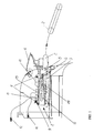
- a receiving space 1 for a lifebuoy 2 is integrated with a signal unit, which is arranged on a runway 3 in a shipbuilding structure.
- the receiving space 1 is closed in the ready position by a pivotally arranged flap 4 and provided with a controllable lock 5. Via an associated gas pressure spring 6, the flap 4 is adjustable in an open position to release an outlet opening for the recorded lifebuoy 2.
- a rope-mechanical backflow device 7 and an ejection device 8 are arranged via a spring / compressed air reservoir 11 in the receiving space 1, which activates the ejection mechanism acting on the lifebuoy 2 via a trigger 9.
- a mechanical energy storage is arranged as a compressed air reservoir 10.
- an associated alternative electromechanical drive is used with an additional supply by an emergency power source in case of voltage loss.
- the control for an ejection of the lifebuoy 2 by remote control with a control switch 12 via an associated switching device 13, for example, from the bridge of the ship, or a manual trigger 14 with an associated switching device 15, first the flap 4 via the gas spring 6 in an open position set and then carried out the start of the ejector 8 for the ejection of the lifebuoy 2.
- a control switch 12 via an associated switching device 13
- a manual trigger 14 with an associated switching device 15
- all tripping operations are performed by redundant drives and controls to allow ejection in any case in the application.
- the lifebuoy 2 with its ejector 8 is guided during ejection on the runway 3.
- Fig. 2 is extended in the drain area 3 by rail elements 16, according to Fig. 3 linearly by gravity telescopically or according to Fig. 4 are formedsausschwenkend.
Landscapes
- Engineering & Computer Science (AREA)
- Mechanical Engineering (AREA)
- Ocean & Marine Engineering (AREA)
- Vending Machines For Individual Products (AREA)
- Automatic Disk Changers (AREA)
- Filling Or Discharging Of Gas Storage Vessels (AREA)
- Emergency Lowering Means (AREA)
- Magnetic Heads (AREA)
- Pinball Game Machines (AREA)
- Portable Nailing Machines And Staplers (AREA)
- Revetment (AREA)
Abstract
Description
- Die Erfindung bezieht sich auf eine Vorrichtung zur Anordnung von Rettungsringen auf Schiffen, die über Halterungen zum Auswurf bereitgestellt sind.
- Es ist bekannt, Rettungsringe in unmittelbarer Nähe der Brücke bzw. im Bereich von Zugängen anzuordnen und im Bedarfsfall manuell aus entsprechenden Halterungen zu lösen. Der Mangel dieser Vorgehensweise besteht darin, daß das Ausbringen im ausreichenden Abstand zum Schiff oftmals nicht gewährleistet wird. Hierbei ist auch zu berücksichtigen, daß die Zugänglichkeit der Rettungsringe von der Brücke nicht gegeben ist.
- Diese bekannte Handhabung hat weiterhin den Nachteil, daß die Rettungsringe optisch in Erscheinung treten und somit im Yachtbereich eine unerwünschte Beeinträchtigung darstellen sowie Umweltbeeinträchtigungen ausgesetzt sind. Zusätzlich ist auch eine Beeinflussung der Radarsignatur möglich.
- Aufgabe der Erfindung ist es, Beeinträchtigungen der Rettungsringe durch Außeneinflüsse zu vermeiden und eine unauffällige Anordnung zu gewährleisten, die mit den anzuwendenden Vorschriften konform ist und eine steuerbare Aktivierung zum Auswerfen im ausreichenden Abstand zum Schiff zu ermöglichen.
- Die Lösung dieser Aufgabe erfolgt erfindungsgemäß dadurch, daß ein Aufnahmeraum für den Rettungsring in einer schiffbaulichen Struktur integriert ist und der Rettungsring in einer im wesentlichen waagerechten bzw. nach unten abgewinkelten Lage aufgenommen ist, wobei eine außenliegende Austrittsöffnung des Aufnahmeraumes durch eine verschwenkbare Klappe im Außenbereich über einen steuerbaren Stellzylinder bedarfsweise freigebbar und eine dem Rettungsring zugeordnete Ausstoßvorrichtung zum Auswurf über außenliegende Auslösevorrichtungen aktivierbar ist.
- Hierdurch besteht die Möglichkeit, eine geschützte optisch ansprechende Lagerung des Rettungsringes zu schaffen und eine vorgegebene Wurfweite beim Ausbringen des Rettungsringes zu gewährleisten sowie auch eine Schnellauslösung von entfernten Orten, wie von Brücken, durchzuführen und damit eine Automatisierung des Ausbringens zu ermöglichen.
- Eine einfache Ausbildung besteht darin, daß die Ausstoßvorrichtung durch einen Federspeicher und/oder Druckluftspeicher gebildet ist.
- Um den Auswurf zu erleichtern, wird vorgeschlagen, daß der Rettungsring auf einer Ablaufbahn in Ausstoßrichtung geführt ist.
- Zur zusätzlichen Führung des Rettungsringes beim Auswurf ist vorgesehen, daß die Ablaufbahn für den Rettungsring bei Öffnung der Klappe über selbsttätig durch Schwerkraft bzw. Federkraft ausfahrbare Schienenelemente im Außenbereich des Aufnahmeraumes verlängerbar ist.
- Ferner wird vorgeschlagen, daß der Rettungsring eine Signaleinheit aufweist.
- Eine günstige Ausbildung besteht darin, daß der Stellzylinder für die Klappe des Aufnahmeraumes als Gasdruckfeder ausgebildet ist.
- Weiterhin wird vorgeschlagen, daß eine seilmechanische Rückstauvorrichtung eines Auswurfmechanismusses angeordnet ist.
- In der Zeichnung sind Ausführungsbeispiele der Erfindung schematisch dargestellt. Es zeigen:
- Fig. 1
- eine Prinzipdarstellung einer Vorrichtung zur etwa waagerechten Aufnahme eines Rettungsringes;
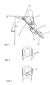
- Fig. 2
- eine weitere Ausführungsform mit einer abgewinkelten Aufnahme des Rettungsringes;
- Fig. 3
- eine Vorrichtung gemäß
Fig. 2 mit ausfahrbaren Schienen für eine Ablaufbahn und - Fig. 4
- eine alternative Schienenanordnung gemäß
Fig. 3 mit ausschwenkbaren Schienen. - Bei der dargestellten Anordnung ist in einer schiffbaulichen Struktur ein Aufnahmeraum 1 für einen Rettungsring 2 mit einer Signaleinheit integriert, der auf einer Ablaufbahn 3 angeordnet ist.
- Der Aufnahmeraum 1 ist in der Bereitstellungsposition durch eine verschwenkbar angeordnete Klappe 4 verschlossen sowie mit einer steuerbaren Verriegelung 5 versehen. Über eine zugeordnete Gasdruckfeder 6 ist die Klappe 4 in eine Öffnungslage einstellbar, um eine Austrittsöffnung für den aufgenommenen Rettungsring 2 freizugeben.
- Im Aufnahmeraum 1 ist zusätzlich eine seilmechanische Rückstauvorrichtung 7 und eine Ausstoßvorrichtung 8 über einen Feder-/Druckluftspeicher 11 angeordnet, der über einen Auslöser 9 den am Rettungsring 2 angreifenden Auswurfmechanismus aktiviert. Hierzu ist ein mechanischer Energiespeicher als Druckluftspeicher 10 angeordnet. Bei Druckverlust wird ein zugeordneter alternativer elektromechanischer Antrieb mit einer zusätzlichen Versorgung durch eine Notstromquelle bei Spannungsverlust eingesetzt.
- Die Ansteuerung für einen Auswurf des Rettungsringes 2 durch Fernauslösung mit einem Steuerschalter 12 über ein zugeordnetes Schaltgerät 13, beispielsweise von der Brücke des Schiffes, oder einem manuellen Auslöser 14 mit einem zugeordneten Schaltgerät 15, wird zuerst die Klappe 4 über die Gasdruckfeder 6 in eine Öffnungslage eingestellt und anschließend der Start der Ausstoßvorrichtung 8 für den Auswurf des Rettungsringes 2 durchgeführt. Hierbei ist vorgesehen, daß alle Auslösevorgänge durch redundante Antriebe und Steuerungen erfolgt, um im Einsatzfall den Auswurf in jedem Fall zu ermöglichen.
- Der Rettungsring 2 mit seiner Ausstoßvorrichtung 8 wird beim Auswurf über die Ablaufbahn 3 geführt. Gemäß
Fig. 2 wird die im Ablaufbereich 3 durch Schienenelemente 16 verlängert, die gemäßFig. 3 linear durch Schwerkraft teleskopartig bzw. gemäßFig. 4 selbstausschwenkend ausgebildet sind.
Claims (7)
- Vorrichtung zur Anordnung von Rettungsringen auf Schiffen, die über Halterungen zum Auswurf bereitgestellt sind, dadurch gekennzeichnet, daß ein Aufnahmeraum (1) für den Rettungsring (2) in einer schiffbaulichen Struktur integriert ist und der Rettungsring (2) in einer im wesentlichen waagerechten bzw. nach unten abgewinkelten Lage aufgenommen ist, wobei eine außenliegende Austrittsöffnung des Aufnahmeraumes (1) durch eine verschwenkbare Klappe (4) im Außenbereich über einen steuerbaren Stellzylinder (6) bedarfsweise freigebbar und eine dem Rettungsring zugeordnete Ausstoßvorrichtung (8) zum Auswurf über außenliegende Auslösevorrichtungen (12, 13) aktivierbar ist.
- Vorrichtung nach Anspruch 1, dadurch gekennzeichnet, daß die Ausstoßvorrichtung (8) durch einen Federspeicher und/oder Druckluftspeicher gebildet ist.
- Vorrichtung nach Anspruch 1 oder 2, dadurch gekennzeichnet, daß der Rettungsring (2) auf einer Ablaufbahn (3) in Ausstoßrichtung geführt ist.
- Vorrichtung nach einem der Ansprüche 1 bis 3, dadurch gekennzeichnet, daß die Ablaufbahn (3) für den Rettungsring (2) bei Öffnung der Klappe (4) über selbsttätig durch Schwerkraft bzw. Federkraft ausfahrbare Schienenelemente (16) im Außenbereich des Aufnahmeraumes (1) verlängerbar ist.
- Vorrichtung nach einem der Ansprüche 1 bis 4, dadurch gekennzeichnet, daß der Rettungsring (2) eine Signaleinheit aufweist.
- Vorrichtung nach einem der Ansprüche 1 bis 5, dadurch gekennzeichnet, daß der Stellzylinder (6) für die Klappe (4) des Aufnahmeraumes (1) als Gasdruckfeder ausgebildet ist.
- Vorrichtung nach einem der Ansprüche 1 bis 6, dadurch gekennzeichnet, daß eine seilmechanische Rückstauvorrichtung (7) eines Auswurfmechanismusses angeordnet ist.
Applications Claiming Priority (1)
| Application Number | Priority Date | Filing Date | Title |
|---|---|---|---|
| DE102007050515 | 2007-10-23 |
Publications (2)
| Publication Number | Publication Date |
|---|---|
| EP2052964A1 true EP2052964A1 (de) | 2009-04-29 |
| EP2052964B1 EP2052964B1 (de) | 2011-04-20 |
Family
ID=39769572
Family Applications (1)
| Application Number | Title | Priority Date | Filing Date |
|---|---|---|---|
| EP08015907A Not-in-force EP2052964B1 (de) | 2007-10-23 | 2008-09-10 | Vorrichtung zur Anordnung und zum Auswurf von Rettungsringen |
Country Status (4)
| Country | Link |
|---|---|
| EP (1) | EP2052964B1 (de) |
| AT (1) | ATE506249T1 (de) |
| DE (1) | DE502008003258D1 (de) |
| DK (1) | DK2052964T3 (de) |
Cited By (4)
| Publication number | Priority date | Publication date | Assignee | Title |
|---|---|---|---|---|
| DE202015105783U1 (de) | 2015-10-30 | 2016-02-03 | Kaefer Schiffsausbau Gmbh | Vorrichtung zum Bereitstellen einer Notfalleinrichtung auf einem Schiff und ein Schiff mit einer solchen Vorrichtung |
| CN108583823A (zh) * | 2018-07-19 | 2018-09-28 | 澳龙船艇科技有限公司 | 一种斜抛式救生圈架 |
| CN110641649A (zh) * | 2019-09-23 | 2020-01-03 | 佛山职业技术学院 | 一种无人救生艇及无人救生艇机群网络系统 |
| CN117341943A (zh) * | 2023-09-19 | 2024-01-05 | 东台市火星船舶设备有限公司 | 一种船载式救生圈定点抛投设备 |
Citations (4)
| Publication number | Priority date | Publication date | Assignee | Title |
|---|---|---|---|---|
| US3696453A (en) | 1970-05-28 | 1972-10-10 | Del Amo Enterprises Inc | Life saving equipment |
| US3945067A (en) * | 1975-02-04 | 1976-03-23 | Salvarezza Robert M | Quick-release storage of a life ring and lifebuoy markers |
| GB2325651A (en) * | 1997-05-27 | 1998-12-02 | Marine Lifeline | Launching apparatus and projectile |
| EP1564133A1 (de) * | 2004-02-13 | 2005-08-17 | Alstom | System zum Verstauen und Aussetzen einer Rettungsinsel |
-
2008
- 2008-09-10 DE DE502008003258T patent/DE502008003258D1/de active Active
- 2008-09-10 EP EP08015907A patent/EP2052964B1/de not_active Not-in-force
- 2008-09-10 AT AT08015907T patent/ATE506249T1/de active
- 2008-09-10 DK DK08015907.2T patent/DK2052964T3/da active
Patent Citations (4)
| Publication number | Priority date | Publication date | Assignee | Title |
|---|---|---|---|---|
| US3696453A (en) | 1970-05-28 | 1972-10-10 | Del Amo Enterprises Inc | Life saving equipment |
| US3945067A (en) * | 1975-02-04 | 1976-03-23 | Salvarezza Robert M | Quick-release storage of a life ring and lifebuoy markers |
| GB2325651A (en) * | 1997-05-27 | 1998-12-02 | Marine Lifeline | Launching apparatus and projectile |
| EP1564133A1 (de) * | 2004-02-13 | 2005-08-17 | Alstom | System zum Verstauen und Aussetzen einer Rettungsinsel |
Non-Patent Citations (1)
| Title |
|---|
| "Lexikon SEEFAHRT", 1988, pages: 457 |
Cited By (4)
| Publication number | Priority date | Publication date | Assignee | Title |
|---|---|---|---|---|
| DE202015105783U1 (de) | 2015-10-30 | 2016-02-03 | Kaefer Schiffsausbau Gmbh | Vorrichtung zum Bereitstellen einer Notfalleinrichtung auf einem Schiff und ein Schiff mit einer solchen Vorrichtung |
| CN108583823A (zh) * | 2018-07-19 | 2018-09-28 | 澳龙船艇科技有限公司 | 一种斜抛式救生圈架 |
| CN110641649A (zh) * | 2019-09-23 | 2020-01-03 | 佛山职业技术学院 | 一种无人救生艇及无人救生艇机群网络系统 |
| CN117341943A (zh) * | 2023-09-19 | 2024-01-05 | 东台市火星船舶设备有限公司 | 一种船载式救生圈定点抛投设备 |
Also Published As
| Publication number | Publication date |
|---|---|
| ATE506249T1 (de) | 2011-05-15 |
| DE502008003258D1 (de) | 2011-06-01 |
| EP2052964B1 (de) | 2011-04-20 |
| DK2052964T3 (da) | 2011-07-25 |
Similar Documents
| Publication | Publication Date | Title |
|---|---|---|
| EP2052964B1 (de) | Vorrichtung zur Anordnung und zum Auswurf von Rettungsringen | |
| DE102015107793A1 (de) | Türgriffanordnung für Fahrzeuge | |
| EP1848020A3 (de) | Handbetätigter Schutzschalter | |
| DE10257267A1 (de) | Fahrzeug, insbesondere Kraftfahrzeug, mit Scheinwerferanbindung für Fußgängerschutz | |
| DE202006003649U1 (de) | Überrollschutzsystem für Kraftfahrzeuge mit einem aktiv aufstellbaren Überrollbügel | |
| DE19521876A1 (de) | Entriegelungsvorrichtung für eine Fensterscheibe, insbesondere für Eisenbahnwaggons, mit einem Schieber | |
| EP1757497B1 (de) | Pyrotechnisch auslösbare Haltevorrichtung für Schutzvorrichtungen in Kraftfahrzeugen | |
| DE4230071A1 (de) | Sprengschneider für Minenverankerungen | |
| EP0489287A2 (de) | Schutzeinrichtung für Fahrzeuge | |
| DE102014215788A1 (de) | Fußgängerschutzvorrichtung für ein Kraftfahrzeug | |
| DE102006001189A1 (de) | Vorrichtung für das automatische Abstoßen von Waffen von einer Ausziehplattform nach Fallschirm-Extraktion | |
| DE102009004354A1 (de) | Sonnenschutzanlage | |
| EP1872990B1 (de) | Personenkraftwagen mit Fondsitzen | |
| EP2733025A1 (de) | Fronthaubenscharnier mit pyrotechnischer Antriebsvorrichtung | |
| DE202005013376U1 (de) | Scheibenheber für Sicherheitsfahrzeuge | |
| DE102014010871B4 (de) | Fahrzeug | |
| EP3032014A2 (de) | Türgriffanordnung für fahrzeuge | |
| DE202010008987U1 (de) | Rauchabzugseinrichtung für eine an einem Rahmen anscharnierte Klappe oder Lichtkuppel | |
| DE1174200B (de) | Tauchschalter zur selbsttaetigen Freigabe des Gases eines geschlossenen Vorratsbehaelters fuer aufblasbare Seerettungsgeraete | |
| DE102007061064A1 (de) | Überrollschutzeinrichtung mit geschossartigem Aufbrechkörper | |
| DE102007061063A1 (de) | Überrollschutzeinrichtung mit glasbrechendem Masseteil | |
| DE102012000373A1 (de) | Verfahren zum Einstellen der Position eines Spoilers sowie Kraftfahrzeug mit einem verstellbaren Spoiler | |
| DE539002C (de) | Eisenbahnschranke mit Vorrichtung zur Abbremsung eines gegen die Schranke anprallenden Fahrzeuges | |
| DE202012001200U1 (de) | Pneumatischer Zweikomponenten-Rettungsstern | |
| EP2694342B1 (de) | Vorrichtung zum abdecken eines betätigungselements, notbetätigungseinrichtung und verfahren zum befestigen einer scheibe |
Legal Events
| Date | Code | Title | Description |
|---|---|---|---|
| PUAI | Public reference made under article 153(3) epc to a published international application that has entered the european phase |
Free format text: ORIGINAL CODE: 0009012 |
|
| 17P | Request for examination filed |
Effective date: 20090103 |
|
| AK | Designated contracting states |
Kind code of ref document: A1 Designated state(s): AT BE BG CH CY CZ DE DK EE ES FI FR GB GR HR HU IE IS IT LI LT LU LV MC MT NL NO PL PT RO SE SI SK TR |
|
| AX | Request for extension of the european patent |
Extension state: AL BA MK RS |
|
| 17Q | First examination report despatched |
Effective date: 20090721 |
|
| AKX | Designation fees paid |
Designated state(s): AT BE BG CH CY CZ DE DK EE ES FI FR GB GR HR HU IE IS IT LI LT LU LV MC MT NL NO PL PT RO SE SI SK TR |
|
| GRAP | Despatch of communication of intention to grant a patent |
Free format text: ORIGINAL CODE: EPIDOSNIGR1 |
|
| GRAS | Grant fee paid |
Free format text: ORIGINAL CODE: EPIDOSNIGR3 |
|
| GRAA | (expected) grant |
Free format text: ORIGINAL CODE: 0009210 |
|
| AK | Designated contracting states |
Kind code of ref document: B1 Designated state(s): AT BE BG CH CY CZ DE DK EE ES FI FR GB GR HR HU IE IS IT LI LT LU LV MC MT NL NO PL PT RO SE SI SK TR |
|
| REG | Reference to a national code |
Ref country code: GB Ref legal event code: FG4D Free format text: NOT ENGLISH |
|
| REG | Reference to a national code |
Ref country code: CH Ref legal event code: EP |
|
| REG | Reference to a national code |
Ref country code: IE Ref legal event code: FG4D Free format text: LANGUAGE OF EP DOCUMENT: GERMAN |
|
| REF | Corresponds to: |
Ref document number: 502008003258 Country of ref document: DE Date of ref document: 20110601 Kind code of ref document: P |
|
| REG | Reference to a national code |
Ref country code: NL Ref legal event code: T3 Ref country code: DE Ref legal event code: R096 Ref document number: 502008003258 Country of ref document: DE Effective date: 20110601 |
|
| REG | Reference to a national code |
Ref country code: DK Ref legal event code: T3 |
|
| LTIE | Lt: invalidation of european patent or patent extension |
Effective date: 20110420 |
|
| PG25 | Lapsed in a contracting state [announced via postgrant information from national office to epo] |
Ref country code: NO Free format text: LAPSE BECAUSE OF FAILURE TO SUBMIT A TRANSLATION OF THE DESCRIPTION OR TO PAY THE FEE WITHIN THE PRESCRIBED TIME-LIMIT Effective date: 20110720 Ref country code: HR Free format text: LAPSE BECAUSE OF FAILURE TO SUBMIT A TRANSLATION OF THE DESCRIPTION OR TO PAY THE FEE WITHIN THE PRESCRIBED TIME-LIMIT Effective date: 20110420 Ref country code: LT Free format text: LAPSE BECAUSE OF FAILURE TO SUBMIT A TRANSLATION OF THE DESCRIPTION OR TO PAY THE FEE WITHIN THE PRESCRIBED TIME-LIMIT Effective date: 20110420 Ref country code: SE Free format text: LAPSE BECAUSE OF FAILURE TO SUBMIT A TRANSLATION OF THE DESCRIPTION OR TO PAY THE FEE WITHIN THE PRESCRIBED TIME-LIMIT Effective date: 20110420 Ref country code: PT Free format text: LAPSE BECAUSE OF FAILURE TO SUBMIT A TRANSLATION OF THE DESCRIPTION OR TO PAY THE FEE WITHIN THE PRESCRIBED TIME-LIMIT Effective date: 20110822 |
|
| REG | Reference to a national code |
Ref country code: IE Ref legal event code: FD4D |
|
| PG25 | Lapsed in a contracting state [announced via postgrant information from national office to epo] |
Ref country code: ES Free format text: LAPSE BECAUSE OF FAILURE TO SUBMIT A TRANSLATION OF THE DESCRIPTION OR TO PAY THE FEE WITHIN THE PRESCRIBED TIME-LIMIT Effective date: 20110731 Ref country code: FI Free format text: LAPSE BECAUSE OF FAILURE TO SUBMIT A TRANSLATION OF THE DESCRIPTION OR TO PAY THE FEE WITHIN THE PRESCRIBED TIME-LIMIT Effective date: 20110420 Ref country code: IS Free format text: LAPSE BECAUSE OF FAILURE TO SUBMIT A TRANSLATION OF THE DESCRIPTION OR TO PAY THE FEE WITHIN THE PRESCRIBED TIME-LIMIT Effective date: 20110820 Ref country code: CY Free format text: LAPSE BECAUSE OF FAILURE TO SUBMIT A TRANSLATION OF THE DESCRIPTION OR TO PAY THE FEE WITHIN THE PRESCRIBED TIME-LIMIT Effective date: 20110420 Ref country code: GR Free format text: LAPSE BECAUSE OF FAILURE TO SUBMIT A TRANSLATION OF THE DESCRIPTION OR TO PAY THE FEE WITHIN THE PRESCRIBED TIME-LIMIT Effective date: 20110721 Ref country code: LV Free format text: LAPSE BECAUSE OF FAILURE TO SUBMIT A TRANSLATION OF THE DESCRIPTION OR TO PAY THE FEE WITHIN THE PRESCRIBED TIME-LIMIT Effective date: 20110420 Ref country code: SI Free format text: LAPSE BECAUSE OF FAILURE TO SUBMIT A TRANSLATION OF THE DESCRIPTION OR TO PAY THE FEE WITHIN THE PRESCRIBED TIME-LIMIT Effective date: 20110420 |
|
| PG25 | Lapsed in a contracting state [announced via postgrant information from national office to epo] |
Ref country code: IE Free format text: LAPSE BECAUSE OF FAILURE TO SUBMIT A TRANSLATION OF THE DESCRIPTION OR TO PAY THE FEE WITHIN THE PRESCRIBED TIME-LIMIT Effective date: 20110420 Ref country code: EE Free format text: LAPSE BECAUSE OF FAILURE TO SUBMIT A TRANSLATION OF THE DESCRIPTION OR TO PAY THE FEE WITHIN THE PRESCRIBED TIME-LIMIT Effective date: 20110420 Ref country code: CZ Free format text: LAPSE BECAUSE OF FAILURE TO SUBMIT A TRANSLATION OF THE DESCRIPTION OR TO PAY THE FEE WITHIN THE PRESCRIBED TIME-LIMIT Effective date: 20110420 |
|
| PLBE | No opposition filed within time limit |
Free format text: ORIGINAL CODE: 0009261 |
|
| STAA | Information on the status of an ep patent application or granted ep patent |
Free format text: STATUS: NO OPPOSITION FILED WITHIN TIME LIMIT |
|
| PG25 | Lapsed in a contracting state [announced via postgrant information from national office to epo] |
Ref country code: RO Free format text: LAPSE BECAUSE OF FAILURE TO SUBMIT A TRANSLATION OF THE DESCRIPTION OR TO PAY THE FEE WITHIN THE PRESCRIBED TIME-LIMIT Effective date: 20110420 Ref country code: PL Free format text: LAPSE BECAUSE OF FAILURE TO SUBMIT A TRANSLATION OF THE DESCRIPTION OR TO PAY THE FEE WITHIN THE PRESCRIBED TIME-LIMIT Effective date: 20110420 Ref country code: SK Free format text: LAPSE BECAUSE OF FAILURE TO SUBMIT A TRANSLATION OF THE DESCRIPTION OR TO PAY THE FEE WITHIN THE PRESCRIBED TIME-LIMIT Effective date: 20110420 |
|
| 26N | No opposition filed |
Effective date: 20120123 |
|
| BERE | Be: lapsed |
Owner name: BLOHM + VOSS SHIPYARDS G.M.B.H. Effective date: 20110930 |
|
| PG25 | Lapsed in a contracting state [announced via postgrant information from national office to epo] |
Ref country code: MC Free format text: LAPSE BECAUSE OF NON-PAYMENT OF DUE FEES Effective date: 20110930 |
|
| REG | Reference to a national code |
Ref country code: DE Ref legal event code: R097 Ref document number: 502008003258 Country of ref document: DE Effective date: 20120123 |
|
| PG25 | Lapsed in a contracting state [announced via postgrant information from national office to epo] |
Ref country code: BE Free format text: LAPSE BECAUSE OF NON-PAYMENT OF DUE FEES Effective date: 20110930 |
|
| PG25 | Lapsed in a contracting state [announced via postgrant information from national office to epo] |
Ref country code: MT Free format text: LAPSE BECAUSE OF FAILURE TO SUBMIT A TRANSLATION OF THE DESCRIPTION OR TO PAY THE FEE WITHIN THE PRESCRIBED TIME-LIMIT Effective date: 20110420 |
|
| REG | Reference to a national code |
Ref country code: CH Ref legal event code: PL |
|
| PG25 | Lapsed in a contracting state [announced via postgrant information from national office to epo] |
Ref country code: LU Free format text: LAPSE BECAUSE OF NON-PAYMENT OF DUE FEES Effective date: 20110910 |
|
| PG25 | Lapsed in a contracting state [announced via postgrant information from national office to epo] |
Ref country code: BG Free format text: LAPSE BECAUSE OF FAILURE TO SUBMIT A TRANSLATION OF THE DESCRIPTION OR TO PAY THE FEE WITHIN THE PRESCRIBED TIME-LIMIT Effective date: 20110720 |
|
| PG25 | Lapsed in a contracting state [announced via postgrant information from national office to epo] |
Ref country code: CH Free format text: LAPSE BECAUSE OF NON-PAYMENT OF DUE FEES Effective date: 20120930 Ref country code: LI Free format text: LAPSE BECAUSE OF NON-PAYMENT OF DUE FEES Effective date: 20120930 |
|
| PG25 | Lapsed in a contracting state [announced via postgrant information from national office to epo] |
Ref country code: TR Free format text: LAPSE BECAUSE OF FAILURE TO SUBMIT A TRANSLATION OF THE DESCRIPTION OR TO PAY THE FEE WITHIN THE PRESCRIBED TIME-LIMIT Effective date: 20110420 |
|
| PG25 | Lapsed in a contracting state [announced via postgrant information from national office to epo] |
Ref country code: HU Free format text: LAPSE BECAUSE OF FAILURE TO SUBMIT A TRANSLATION OF THE DESCRIPTION OR TO PAY THE FEE WITHIN THE PRESCRIBED TIME-LIMIT Effective date: 20110420 |
|
| REG | Reference to a national code |
Ref country code: DE Ref legal event code: R082 Ref document number: 502008003258 Country of ref document: DE Representative=s name: ELBPATENT - MARSCHALL & PARTNER PARTGMBB, DE |
|
| REG | Reference to a national code |
Ref country code: AT Ref legal event code: MM01 Ref document number: 506249 Country of ref document: AT Kind code of ref document: T Effective date: 20130910 |
|
| PG25 | Lapsed in a contracting state [announced via postgrant information from national office to epo] |
Ref country code: AT Free format text: LAPSE BECAUSE OF NON-PAYMENT OF DUE FEES Effective date: 20130910 |
|
| REG | Reference to a national code |
Ref country code: FR Ref legal event code: PLFP Year of fee payment: 9 |
|
| PGFP | Annual fee paid to national office [announced via postgrant information from national office to epo] |
Ref country code: DK Payment date: 20160920 Year of fee payment: 9 Ref country code: NL Payment date: 20160920 Year of fee payment: 9 Ref country code: GB Payment date: 20160920 Year of fee payment: 9 |
|
| PGFP | Annual fee paid to national office [announced via postgrant information from national office to epo] |
Ref country code: FR Payment date: 20160921 Year of fee payment: 9 |
|
| PGFP | Annual fee paid to national office [announced via postgrant information from national office to epo] |
Ref country code: IT Payment date: 20160922 Year of fee payment: 9 |
|
| PGFP | Annual fee paid to national office [announced via postgrant information from national office to epo] |
Ref country code: DE Payment date: 20170928 Year of fee payment: 10 |
|
| REG | Reference to a national code |
Ref country code: DK Ref legal event code: EBP Effective date: 20170930 |
|
| REG | Reference to a national code |
Ref country code: NL Ref legal event code: MM Effective date: 20171001 |
|
| GBPC | Gb: european patent ceased through non-payment of renewal fee |
Effective date: 20170910 |
|
| PG25 | Lapsed in a contracting state [announced via postgrant information from national office to epo] |
Ref country code: NL Free format text: LAPSE BECAUSE OF NON-PAYMENT OF DUE FEES Effective date: 20171001 |
|
| REG | Reference to a national code |
Ref country code: FR Ref legal event code: ST Effective date: 20180531 |
|
| PG25 | Lapsed in a contracting state [announced via postgrant information from national office to epo] |
Ref country code: GB Free format text: LAPSE BECAUSE OF NON-PAYMENT OF DUE FEES Effective date: 20170910 |
|
| PG25 | Lapsed in a contracting state [announced via postgrant information from national office to epo] |
Ref country code: IT Free format text: LAPSE BECAUSE OF NON-PAYMENT OF DUE FEES Effective date: 20170910 Ref country code: FR Free format text: LAPSE BECAUSE OF NON-PAYMENT OF DUE FEES Effective date: 20171002 |
|
| PG25 | Lapsed in a contracting state [announced via postgrant information from national office to epo] |
Ref country code: DK Free format text: LAPSE BECAUSE OF NON-PAYMENT OF DUE FEES Effective date: 20170930 |
|
| REG | Reference to a national code |
Ref country code: DE Ref legal event code: R119 Ref document number: 502008003258 Country of ref document: DE |
|
| PG25 | Lapsed in a contracting state [announced via postgrant information from national office to epo] |
Ref country code: DE Free format text: LAPSE BECAUSE OF NON-PAYMENT OF DUE FEES Effective date: 20190402 |