EP2052967A1 - Verbesserung an Drehflügelflugzeugen, die mit Turbotriebwerken ausgestattet sind - Google Patents
Verbesserung an Drehflügelflugzeugen, die mit Turbotriebwerken ausgestattet sind Download PDFInfo
- Publication number
- EP2052967A1 EP2052967A1 EP08017873A EP08017873A EP2052967A1 EP 2052967 A1 EP2052967 A1 EP 2052967A1 EP 08017873 A EP08017873 A EP 08017873A EP 08017873 A EP08017873 A EP 08017873A EP 2052967 A1 EP2052967 A1 EP 2052967A1
- Authority
- EP
- European Patent Office
- Prior art keywords
- external compressor
- turbine engine
- rotorcraft
- turbine
- btp
- Prior art date
- Legal status (The legal status is an assumption and is not a legal conclusion. Google has not performed a legal analysis and makes no representation as to the accuracy of the status listed.)
- Granted
Links
- 230000007246 mechanism Effects 0.000 claims abstract description 21
- 230000005540 biological transmission Effects 0.000 claims abstract description 13
- 239000003638 chemical reducing agent Substances 0.000 claims description 6
- 230000006835 compression Effects 0.000 claims description 6
- 238000007906 compression Methods 0.000 claims description 6
- 238000001816 cooling Methods 0.000 claims description 3
- 239000012530 fluid Substances 0.000 claims description 3
- 239000007789 gas Substances 0.000 description 3
- 238000013461 design Methods 0.000 description 2
- 238000011161 development Methods 0.000 description 2
- 238000012986 modification Methods 0.000 description 2
- 230000004048 modification Effects 0.000 description 2
- 238000012360 testing method Methods 0.000 description 2
- 230000006978 adaptation Effects 0.000 description 1
- 238000007792 addition Methods 0.000 description 1
- 239000003570 air Substances 0.000 description 1
- 238000010586 diagram Methods 0.000 description 1
- 239000000446 fuel Substances 0.000 description 1
- 238000005339 levitation Methods 0.000 description 1
- 239000000314 lubricant Substances 0.000 description 1
- 238000004519 manufacturing process Methods 0.000 description 1
- 239000003921 oil Substances 0.000 description 1
- 239000003507 refrigerant Substances 0.000 description 1
- 238000013519 translation Methods 0.000 description 1
- XLYOFNOQVPJJNP-UHFFFAOYSA-N water Substances O XLYOFNOQVPJJNP-UHFFFAOYSA-N 0.000 description 1
Images


Classifications
-
- B—PERFORMING OPERATIONS; TRANSPORTING
- B64—AIRCRAFT; AVIATION; COSMONAUTICS
- B64C—AEROPLANES; HELICOPTERS
- B64C27/00—Rotorcraft; Rotors peculiar thereto
- B64C27/04—Helicopters
- B64C27/12—Rotor drives
-
- B—PERFORMING OPERATIONS; TRANSPORTING
- B64—AIRCRAFT; AVIATION; COSMONAUTICS
- B64C—AEROPLANES; HELICOPTERS
- B64C27/00—Rotorcraft; Rotors peculiar thereto
- B64C27/04—Helicopters
- B64C27/12—Rotor drives
- B64C27/16—Drive of rotors by means, e.g. propellers, mounted on rotor blades
- B64C27/18—Drive of rotors by means, e.g. propellers, mounted on rotor blades the means being jet-reaction apparatus
-
- B—PERFORMING OPERATIONS; TRANSPORTING
- B64—AIRCRAFT; AVIATION; COSMONAUTICS
- B64D—EQUIPMENT FOR FITTING IN OR TO AIRCRAFT; FLIGHT SUITS; PARACHUTES; ARRANGEMENT OR MOUNTING OF POWER PLANTS OR PROPULSION TRANSMISSIONS IN AIRCRAFT
- B64D27/00—Arrangement or mounting of power plants in aircraft; Aircraft characterised by the type or position of power plants
- B64D27/02—Aircraft characterised by the type or position of power plants
- B64D27/10—Aircraft characterised by the type or position of power plants of gas-turbine type
-
- B—PERFORMING OPERATIONS; TRANSPORTING
- B64—AIRCRAFT; AVIATION; COSMONAUTICS
- B64D—EQUIPMENT FOR FITTING IN OR TO AIRCRAFT; FLIGHT SUITS; PARACHUTES; ARRANGEMENT OR MOUNTING OF POWER PLANTS OR PROPULSION TRANSMISSIONS IN AIRCRAFT
- B64D33/00—Arrangement in aircraft of power plant parts or auxiliaries not otherwise provided for
- B64D33/02—Arrangement in aircraft of power plant parts or auxiliaries not otherwise provided for of combustion air intakes
-
- B—PERFORMING OPERATIONS; TRANSPORTING
- B64—AIRCRAFT; AVIATION; COSMONAUTICS
- B64D—EQUIPMENT FOR FITTING IN OR TO AIRCRAFT; FLIGHT SUITS; PARACHUTES; ARRANGEMENT OR MOUNTING OF POWER PLANTS OR PROPULSION TRANSMISSIONS IN AIRCRAFT
- B64D35/00—Transmitting power from power plants to propellers or rotors; Arrangements of transmissions
- B64D35/02—Transmitting power from power plants to propellers or rotors; Arrangements of transmissions specially adapted for specific power plants
-
- F—MECHANICAL ENGINEERING; LIGHTING; HEATING; WEAPONS; BLASTING
- F02—COMBUSTION ENGINES; HOT-GAS OR COMBUSTION-PRODUCT ENGINE PLANTS
- F02C—GAS-TURBINE PLANTS; AIR INTAKES FOR JET-PROPULSION PLANTS; CONTROLLING FUEL SUPPLY IN AIR-BREATHING JET-PROPULSION PLANTS
- F02C3/00—Gas-turbine plants characterised by the use of combustion products as the working fluid
- F02C3/04—Gas-turbine plants characterised by the use of combustion products as the working fluid having a turbine driving a compressor
- F02C3/10—Gas-turbine plants characterised by the use of combustion products as the working fluid having a turbine driving a compressor with another turbine driving an output shaft but not driving the compressor
- F02C3/103—Gas-turbine plants characterised by the use of combustion products as the working fluid having a turbine driving a compressor with another turbine driving an output shaft but not driving the compressor the compressor being of the centrifugal type
-
- F—MECHANICAL ENGINEERING; LIGHTING; HEATING; WEAPONS; BLASTING
- F02—COMBUSTION ENGINES; HOT-GAS OR COMBUSTION-PRODUCT ENGINE PLANTS
- F02C—GAS-TURBINE PLANTS; AIR INTAKES FOR JET-PROPULSION PLANTS; CONTROLLING FUEL SUPPLY IN AIR-BREATHING JET-PROPULSION PLANTS
- F02C7/00—Features, components parts, details or accessories, not provided for in, or of interest apart form groups F02C1/00 - F02C6/00; Air intakes for jet-propulsion plants
- F02C7/12—Cooling of plants
- F02C7/14—Cooling of plants of fluids in the plant, e.g. lubricant or fuel
- F02C7/141—Cooling of plants of fluids in the plant, e.g. lubricant or fuel of working fluid
- F02C7/143—Cooling of plants of fluids in the plant, e.g. lubricant or fuel of working fluid before or between the compressor stages
-
- F—MECHANICAL ENGINEERING; LIGHTING; HEATING; WEAPONS; BLASTING
- F02—COMBUSTION ENGINES; HOT-GAS OR COMBUSTION-PRODUCT ENGINE PLANTS
- F02C—GAS-TURBINE PLANTS; AIR INTAKES FOR JET-PROPULSION PLANTS; CONTROLLING FUEL SUPPLY IN AIR-BREATHING JET-PROPULSION PLANTS
- F02C7/00—Features, components parts, details or accessories, not provided for in, or of interest apart form groups F02C1/00 - F02C6/00; Air intakes for jet-propulsion plants
- F02C7/36—Power transmission arrangements between the different shafts of the gas turbine plant, or between the gas-turbine plant and the power user
-
- F—MECHANICAL ENGINEERING; LIGHTING; HEATING; WEAPONS; BLASTING
- F05—INDEXING SCHEMES RELATING TO ENGINES OR PUMPS IN VARIOUS SUBCLASSES OF CLASSES F01-F04
- F05D—INDEXING SCHEME FOR ASPECTS RELATING TO NON-POSITIVE-DISPLACEMENT MACHINES OR ENGINES, GAS-TURBINES OR JET-PROPULSION PLANTS
- F05D2220/00—Application
- F05D2220/30—Application in turbines
- F05D2220/32—Application in turbines in gas turbines
- F05D2220/329—Application in turbines in gas turbines in helicopters
-
- Y—GENERAL TAGGING OF NEW TECHNOLOGICAL DEVELOPMENTS; GENERAL TAGGING OF CROSS-SECTIONAL TECHNOLOGIES SPANNING OVER SEVERAL SECTIONS OF THE IPC; TECHNICAL SUBJECTS COVERED BY FORMER USPC CROSS-REFERENCE ART COLLECTIONS [XRACs] AND DIGESTS
- Y02—TECHNOLOGIES OR APPLICATIONS FOR MITIGATION OR ADAPTATION AGAINST CLIMATE CHANGE
- Y02T—CLIMATE CHANGE MITIGATION TECHNOLOGIES RELATED TO TRANSPORTATION
- Y02T50/00—Aeronautics or air transport
- Y02T50/60—Efficient propulsion technologies, e.g. for aircraft
Definitions
- the present invention relates to improvements made to rotorcraft which are equipped with one or more turboshaft engines.
- the technical field of the invention is that of the manufacture of helicopters.
- a rotorcraft has at least one rotor equipped with blades, sometimes called the main rotor, whose rotation allows lift and movement of the rotorcraft.
- a rotorcraft also includes one, two or three turbine engines used to drive the main rotor, where appropriate an anti-torque rotor, and various accessories (alternator and pump (s) in particular).
- a transmission mechanism sometimes referred to as a main gearbox - here after BTP -, for this purpose connects an output shaft of the turbine engine to the main rotor shaft, this mechanism comprising in particular a speed reducer.
- Such mechanisms are described, for example, in patents US 3002710 , US 3255825 and US 4811627 .
- Each turbine engine comprises an axial compressor and / or centrifugal, which generally comprises several wheels forming as many compression stages, and a first impeller (rotating) of the compressor; the turbine engine also comprises a second turbine - said power turbine or free turbine - which extends downstream of the first turbine - with reference to the direction of flow of the gases in the engine - generally coaxially with it.
- the free turbine which is rotatably mounted relative to the first turbine, transforms the thrust exerted by the gases on its blades in mechanical torque "engine"; this driving torque is transmitted by the shaft of the free turbine, then by a speed reducer generally integrated in the turbine engine, and by an output shaft of the turbine engine which can extend laterally and externally thereto, for example parallel to the common axis of rotation of the compressor and the first and second turbines.
- the driving power required to drive a rotorcraft varies greatly depending on the performance expected for the rotorcraft and the environment, including the speed of translation of the rotorcraft, the onboard weight, the ambient temperature, the atmospheric pressure and / or altitude.
- the power supplied by a turbine engine varies significantly depending on atmospheric pressure and / or altitude in particular.
- An object of the invention is to propose a remedy - at least partial - to this situation.
- a rotorcraft with an additional external air compressor, separated from the - external to - turbine engine, as well as an air transport duct connecting the output of the external compressor to the turbine engine inlet to deliver air compressor input to the turbine engine by the external compressor.
- the invention makes it possible to increase the mechanical power supplied by the turbine engine (s), without modifying the turbine (s), thanks to the increase in the pressure obtained at the inlet of the integrated internal compressor. to the (x) turbine engine (s), which is performed by the external compressor external to the (x) turbine engine (s).
- the external compressor has, under normal conditions of temperature and pressure, for its nominal speed of rotation, a compression ratio lying in a range from about 1.01 to about 2, in particular in the range of 1.05. about 1.5 about.
- the external compressor comprises a single impeller wheel, i.e. a single stage, axial wheel type.
- the external compressor may comprise several axial and / or centrifugal wheels, i.e., several stages.
- the wheel (s) of the external compressor may comprise a device for varying the orientation of the blades making it possible to vary the level of compression obtained.
- the external compressor is arranged to be driven directly or indirectly by the turbine engine (s); for this purpose, the external compressor may be arranged to be driven by the free turbine, if necessary via a speed reducer, and / or a transmission shaft, or the main transmission mechanism (BTP ) of the rotorcraft, or can be arranged to be driven by an electric motor powered by energy, via a generator-such as an alternator- and a battery, by the turbine engine or the BTP.
- a generator- such as an alternator- and a battery
- the external compressor may comprise a device for varying its speed of rotation also making it possible to vary the level of compression obtained.
- the rotorcraft further comprises a heat exchanger disposed in the air transport duct connecting the external compressor to the turbine engine; the heat exchanger is connected to a fluid transport circuit (water, air, oil, or refrigerant), the circulation of this fluid in the exchanger for cooling the compressed air by the external compressor.
- a fluid transport circuit water, air, oil, or refrigerant
- the turbine engine may comprise two output shafts: a first shaft, which may be coaxial with the shaft common to the internal compressor and the first turbine of the turbine engine, and which may extend inside of the common shaft, can be used to drive a propulsion propeller and / or the external compressor; a second shaft is used to drive the main rotor of the rotorcraft via the BTP mechanism.
- the external compressor when the external compressor is driven by the BTP, it can be located in front of it, with reference to the forward direction of the rotorcraft. Conversely, especially when the external compressor is driven by an output shaft of the turbine engine, it can be located behind the BTP.
- a rotorcraft comprising two turboshaft engines may comprise a single external compressor delivering pressurized air to the two turbine engines, or two external compressors supplying the two turboshaft engines respectively.
- the compressed air by the external compressor (s) can be delivered to both - or to only one of the two - turboshaft engines.
- a motorized damper may be arranged in the transport duct (s) for connecting the external compressor (s) to the turbine engines.
- the invention makes it possible to reduce the specific consumption of a rotorcraft in cruising mode.
- the invention proposes a simple, inexpensive and compact system, which makes it possible to increase the power output provided by a rotorcraft turbine engine.
- the figure 1 is a simplified diagram illustrating a rotorcraft turbine engine and an external compressor “supercharging” this turbine engine, which is driven by the turbine engine, according to a first embodiment of the invention.
- the figure 2 illustrates schematically, in plan view, a rotorcraft equipped with two turboshaft engines and an external compressor pressurization common to the turbine engines, according to another embodiment of the invention.
- the figure 3 schematically illustrates, in side view, another embodiment of the invention.
- FIG 4 schematically illustrates, in plan view, another embodiment of the invention in which a rotorcraft is equipped with two turbine engines and two external compressors.
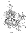
- the figure 5 schematically illustrates, in perspective view, a power transmission mechanism between two respective output shafts of two turbine engines (not shown) and a rotor of the rotorcraft, as well as two external compressors and their respective drive mechanisms by the turbine engines and / or the BTP, according to another embodiment of the invention.
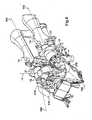
- the figure 6 illustrates schematically, in perspective view, the implementation of two external compressors in two air supply ducts of two turbine engines of a rotorcraft, according to another embodiment of the invention.
- the invention relates to helicopters 10 and other rotorcraft including at least one rotor 11 advance and levitation, which is equipped with blades 12, is rotated along a substantially vertical axis 14, by one or more turbine engines 13.
- a main gearbox - BTP - connects for this purpose a shaft 15, 16 output of each turbine engine to the shaft 17 of the main rotor, this mechanism comprising in particular a speed reducer (cf. figure 5 ).
- each turbine engine comprises an internal compressor 130 and a first turbine 131 integral in rotation with the internal compressor 130; the turbine engine also comprises a free turbine 132 which extends downstream of the first turbine by reference to the flow direction 133 of the gas in the engine.
- the free turbine produces a motor torque which is transmitted by the shaft 134 of the free turbine, then by a speed reducer 135 and by an output shaft 15 of the turbine engine which extends laterally and externally thereto, according to a axis 150 parallel to the common axis 136 of rotation of the internal compressor 130 and the first and second turbines 131, 132.
- the turbine engine (s) 13 thus drive (s) a shaft 18 ( figures 1 , 3 , 5 ) entry of the BTP.
- the illustrated power increase system figure 1 comprises an external compressor 19 of air, distinct from the turbine engine, and an air cooler 20 successively arranged in this order in an air transport duct 21 which connects the external compressor 19 to the air intake 22 of the turbine engine 13.
- the external compressor 19 comprises a rotor wheel rotatably mounted along an axis 190 and driven in rotation by the shaft 15, by means of pinions 23, 24 respectively integral with the shaft 15 and the wheel of the external compressor.
- the air entering the duct 21 passes through the external compressor 19 which compresses it; the compressed air 26 leaving the external compressor 19 passes through the exchanger 20 which cools it; the cooled compressed air 27 leaving the exchanger 20 enters the turbine engine 13 through its air inlet 22.
- the external compressor 19 is rotated by a shaft 191 moved by the BTP mechanism for driving the main rotor.
- the external compressor 19 is disposed in front of the BTP while the two turbine engines 13 are arranged behind the BTP; the exchanger 20 and the duct 21 extend partly in front of the BTP, and partly on either side thereof, the duct 21 connecting the external compressor 19 to the inlet 22 of the turbine engines 13.
- two shafts 15a and 15b of axis 150 connect the output of the output gear 135 of the turbine engine 13 to the input shaft 18 of the BTP.
- a transmission system symbolically represented as a belt, connects the shaft 15a to the shaft 191 of the external compressor 19, for the drive of the latter by the output shaft 15a, 15b of the turbine engine.
- the impeller of the external compressor is disposed downstream of a filter or gate 28 fitted to the air inlet of the duct 21.
- the two external compressors 19 are disposed on either side of the BTP, behind the latter, in the vicinity of the respective lateral air inlets 210 of two ducts 21 for air transport.
- Each conduit 21 is provided with a bypass 21a for delivering a portion of the compressed air by each external compressor 19 to a heat exchanger 29 (radiator) for cooling a lubricant of the BTP.
- the respective shafts 15, 16 of two turboshaft engines drive a shaft 18 input of the BTP through two pinions 30, 31 meshing with the shafts 15, 16 and with another pinion 32 integral with the shaft 18 and a shaft 33 for driving an anti-torque rotor - "tail rotor" - not shown.
- a pair of bevel gears 34 serves to drive a shaft 36 by the shaft 16
- another pair of bevel gears 35 serves to drive the shaft 191 of the external compressor 19 by the shaft 36.
- FIG. 5 Although only one external compressor is shown figure 5 , which is driven by the shaft 16, it is understood that a second compressor external can be driven by a device identical to the device comprising the elements 34 to 36, by the shaft 15, in the case of a configuration identical or similar to those of figures 4 and 6 where the rotorcraft is equipped with two external boosters 19 "supercharging" two turboshaft engines; only part of this device is represented figure 5 so as not to obscure it.
- the figure 6 partially illustrates a helicopter equipped with two external compressors 19 arranged in two ducts 21 extending to the left and right of the BTP, in front of the turbine engines 13.
- each external compressor can be rotated by a variable speed electric motor; Moreover, the pitch of the moving blades of the external compressor can be adjustable in order to vary the compression ratio obtained.
Landscapes
- Engineering & Computer Science (AREA)
- Mechanical Engineering (AREA)
- Chemical & Material Sciences (AREA)
- Combustion & Propulsion (AREA)
- Aviation & Aerospace Engineering (AREA)
- General Engineering & Computer Science (AREA)
- Structures Of Non-Positive Displacement Pumps (AREA)
Applications Claiming Priority (1)
| Application Number | Priority Date | Filing Date | Title |
|---|---|---|---|
| FR0707547A FR2922860B1 (fr) | 2007-10-26 | 2007-10-26 | Amelioration aux giravions equipes de turbomoteurs |
Publications (2)
| Publication Number | Publication Date |
|---|---|
| EP2052967A1 true EP2052967A1 (de) | 2009-04-29 |
| EP2052967B1 EP2052967B1 (de) | 2010-05-05 |
Family
ID=39363991
Family Applications (1)
| Application Number | Title | Priority Date | Filing Date |
|---|---|---|---|
| EP08017873A Ceased EP2052967B1 (de) | 2007-10-26 | 2008-10-13 | Verbesserung an Drehflügelflugzeugen, die mit Turbotriebwerken ausgestattet sind |
Country Status (8)
| Country | Link |
|---|---|
| US (1) | US20090113871A1 (de) |
| EP (1) | EP2052967B1 (de) |
| KR (1) | KR20090042718A (de) |
| CN (1) | CN101417592B (de) |
| CA (1) | CA2641962C (de) |
| DE (1) | DE602008001141D1 (de) |
| FR (1) | FR2922860B1 (de) |
| RU (1) | RU2458826C2 (de) |
Cited By (2)
| Publication number | Priority date | Publication date | Assignee | Title |
|---|---|---|---|---|
| EP2963247A1 (de) * | 2014-07-01 | 2016-01-06 | United Technologies Corporation | Kombinierter zweimotorzyklus mit mindestens einem rekuperativen zyklusmotor für einen rotorantrieb |
| WO2016020607A1 (fr) * | 2014-08-07 | 2016-02-11 | Turbomeca | Dispositif d'assistance rapide pour une turbomachine a turbine libre d'un aéronef |
Families Citing this family (20)
| Publication number | Priority date | Publication date | Assignee | Title |
|---|---|---|---|---|
| FR2899640B1 (fr) * | 2006-04-05 | 2011-11-25 | Eurocopter France | Procede et dispositif pour realiser un controle de l'etat de sante d'un turbomoteur d'un giravion bimoteur |
| FR2961260B1 (fr) * | 2010-06-15 | 2014-05-02 | Turbomeca | Architecture de turbomoteur non lubrifie |
| US9267438B2 (en) | 2011-10-11 | 2016-02-23 | Pratt & Whitney Canada Corp. | Starting of aircraft engine |
| US9429077B2 (en) * | 2011-12-06 | 2016-08-30 | Pratt & Whitney Canada Corp. | Multiple turboshaft engine control method and system for helicopters |
| US9180964B2 (en) | 2013-03-15 | 2015-11-10 | Bell Helicopter Textron Inc. | Autorotative enhancement system |
| FR3008679B1 (fr) * | 2013-07-16 | 2015-08-14 | Eurocopter France | Installation motrice modulaire et aeronef muni d'un rotor de sustentation |
| FR3019222B1 (fr) * | 2014-03-27 | 2018-07-13 | Safran Helicopter Engines | Turbomoteur, helicoptere bimoteur equipe d'un tel turbomoteur et procede d'optimisation du regime de super-ralenti a puissance nulle d'un tel helicoptere bimoteur |
| FR3019588B1 (fr) * | 2014-04-08 | 2019-06-14 | Safran Helicopter Engines | Dispositif d'assistance d'un systeme propulsif a propergol solide d'un helicoptere monomoteur, helicoptere monomoteur comprenant un tel dispositif et procede correspondant |
| FR3024180B1 (fr) * | 2014-07-28 | 2016-07-22 | Turbomeca | Dispositif pneumatique de reactivation rapide d'un turbomoteur, architecture d'un systeme propulsif d'un helicoptere multi-moteur equipe d'un tel dispositif et helicoptere correspondant |
| US11148822B2 (en) * | 2015-09-15 | 2021-10-19 | Sikorsky Aircraft Corporation | Drive system arrangement for rotorcraft |
| CN107757929A (zh) * | 2016-08-23 | 2018-03-06 | 吴茂盛 | 空气动力直升机 |
| US10753225B2 (en) * | 2017-03-31 | 2020-08-25 | The Boeing Company | Engine turning motor via pneumatic or hydraulic motor |
| US11186185B2 (en) * | 2017-05-31 | 2021-11-30 | Textron Innovations Inc. | Rotor brake effect by using electric distributed anti-torque generators and opposing electric motor thrust to slow a main rotor |
| US12570391B2 (en) | 2017-08-10 | 2026-03-10 | Paul NEISER | Apparatus and method for fluid manipulation |
| JP6974616B2 (ja) * | 2017-08-10 | 2021-12-01 | ネイサー、ポール | 流体操作装置アセンブリ、流体操作装置、及び航空機 |
| US12270301B2 (en) | 2017-08-10 | 2025-04-08 | Paul NEISER | System and method for fluid manipulation |
| CN109720586A (zh) * | 2017-10-30 | 2019-05-07 | 成都飞机工业(集团)有限责任公司 | 一种附面层隔道 |
| US11267563B2 (en) | 2018-10-29 | 2022-03-08 | Pratt & Whitney Canada Corp. | Aircraft engine with clutch and mechanical lock |
| JP7049234B2 (ja) * | 2018-11-15 | 2022-04-06 | 本田技研工業株式会社 | ハイブリッド飛行体 |
| CN112173137B (zh) * | 2020-09-25 | 2022-09-30 | 中国直升机设计研究所 | 一种直升机降温进气道 |
Citations (11)
| Publication number | Priority date | Publication date | Assignee | Title |
|---|---|---|---|---|
| US2923128A (en) | 1955-08-17 | 1960-02-02 | United Aircraft Corp | Fuel control for a split turbine type power plant |
| US3002710A (en) | 1956-05-15 | 1961-10-03 | Sud Aviation | Helicopters |
| US3195349A (en) | 1963-01-07 | 1965-07-20 | Boeing Co | Method and apparatus for determining the available power output of an engine |
| US3255825A (en) | 1962-03-14 | 1966-06-14 | Sud Aviation | Transmission boxes for multi-engine, single-rotor helicopters |
| US3548597A (en) * | 1968-09-16 | 1970-12-22 | Alexander Hossen Etessam | Turbine engine for aircraft having a supplementary compressor driven by a supplementary turbine |
| EP0282784A2 (de) | 1987-03-17 | 1988-09-21 | Mtu Motoren- Und Turbinen-Union MàNchen Gmbh | Gasturbinenanlage für Hubschrauber |
| US4811627A (en) | 1984-08-06 | 1989-03-14 | Aerospatiale Societe Nationale Industrielle | Main transmission gearbox for a twin-engined helicopter |
| US6308512B1 (en) | 1999-06-10 | 2001-10-30 | Enhanced Turbine Output Holding, Llc | Supercharging system for gas turbines |
| EP1362984A2 (de) | 2002-05-16 | 2003-11-19 | ROLLS-ROYCE plc | Gasturbine |
| US20060016197A1 (en) * | 2004-07-21 | 2006-01-26 | Epstein Stanley W | Onboard supplemental power system at varying high altitudes |
| EP1712761A2 (de) | 2005-04-08 | 2006-10-18 | United Technologies Corporation | Elektrisch gekoppeltes Zweiwellen-Gasturbinentriebwerk |
Family Cites Families (4)
| Publication number | Priority date | Publication date | Assignee | Title |
|---|---|---|---|---|
| US3922852A (en) * | 1973-10-17 | 1975-12-02 | Gen Electric | Variable pitch fan for gas turbine engine |
| RU2236991C1 (ru) * | 2002-12-30 | 2004-09-27 | Открытое Акционерное Общество "Московский Вертолетный Завод Им. М.Л. Миля" | Вентиляторная установка вертолета |
| US20050151001A1 (en) * | 2003-07-02 | 2005-07-14 | Loper Arthur W. | Compound helicopter |
| RU2282564C2 (ru) * | 2004-10-21 | 2006-08-27 | Валентин Алексеевич Малкин | Вертолет |
-
2007
- 2007-10-26 FR FR0707547A patent/FR2922860B1/fr not_active Expired - Fee Related
-
2008
- 2008-10-13 EP EP08017873A patent/EP2052967B1/de not_active Ceased
- 2008-10-13 DE DE602008001141T patent/DE602008001141D1/de active Active
- 2008-10-20 KR KR1020080102720A patent/KR20090042718A/ko not_active Ceased
- 2008-10-20 CA CA2641962A patent/CA2641962C/fr active Active
- 2008-10-22 RU RU2008141617/11A patent/RU2458826C2/ru active
- 2008-10-24 US US12/257,436 patent/US20090113871A1/en not_active Abandoned
- 2008-10-27 CN CN2008101747473A patent/CN101417592B/zh not_active Expired - Fee Related
Patent Citations (11)
| Publication number | Priority date | Publication date | Assignee | Title |
|---|---|---|---|---|
| US2923128A (en) | 1955-08-17 | 1960-02-02 | United Aircraft Corp | Fuel control for a split turbine type power plant |
| US3002710A (en) | 1956-05-15 | 1961-10-03 | Sud Aviation | Helicopters |
| US3255825A (en) | 1962-03-14 | 1966-06-14 | Sud Aviation | Transmission boxes for multi-engine, single-rotor helicopters |
| US3195349A (en) | 1963-01-07 | 1965-07-20 | Boeing Co | Method and apparatus for determining the available power output of an engine |
| US3548597A (en) * | 1968-09-16 | 1970-12-22 | Alexander Hossen Etessam | Turbine engine for aircraft having a supplementary compressor driven by a supplementary turbine |
| US4811627A (en) | 1984-08-06 | 1989-03-14 | Aerospatiale Societe Nationale Industrielle | Main transmission gearbox for a twin-engined helicopter |
| EP0282784A2 (de) | 1987-03-17 | 1988-09-21 | Mtu Motoren- Und Turbinen-Union MàNchen Gmbh | Gasturbinenanlage für Hubschrauber |
| US6308512B1 (en) | 1999-06-10 | 2001-10-30 | Enhanced Turbine Output Holding, Llc | Supercharging system for gas turbines |
| EP1362984A2 (de) | 2002-05-16 | 2003-11-19 | ROLLS-ROYCE plc | Gasturbine |
| US20060016197A1 (en) * | 2004-07-21 | 2006-01-26 | Epstein Stanley W | Onboard supplemental power system at varying high altitudes |
| EP1712761A2 (de) | 2005-04-08 | 2006-10-18 | United Technologies Corporation | Elektrisch gekoppeltes Zweiwellen-Gasturbinentriebwerk |
Cited By (8)
| Publication number | Priority date | Publication date | Assignee | Title |
|---|---|---|---|---|
| EP2963247A1 (de) * | 2014-07-01 | 2016-01-06 | United Technologies Corporation | Kombinierter zweimotorzyklus mit mindestens einem rekuperativen zyklusmotor für einen rotorantrieb |
| US10066547B2 (en) | 2014-07-01 | 2018-09-04 | United Technologies Corporation | Combined two engine cycle with at least one recuperated cycle engine for rotor drive |
| US10669933B2 (en) | 2014-07-01 | 2020-06-02 | Raytheon Technologies Corporation | Combined two engine cycle with at least one recuperated cycle engine for rotor drive |
| WO2016020607A1 (fr) * | 2014-08-07 | 2016-02-11 | Turbomeca | Dispositif d'assistance rapide pour une turbomachine a turbine libre d'un aéronef |
| FR3024707A1 (fr) * | 2014-08-07 | 2016-02-12 | Turbomeca | Dispositif d'assistance rapide pour une turbomachine a turbine libre d'un aeronef |
| CN106661956A (zh) * | 2014-08-07 | 2017-05-10 | 赛峰直升机发动机 | 航空器的自由涡轮发动机的快速辅助装置 |
| US9828917B2 (en) | 2014-08-07 | 2017-11-28 | Safran Helicopter Engines | Rapid assistance device for a free turbine engine of an aircraft |
| CN106661956B (zh) * | 2014-08-07 | 2018-11-09 | 赛峰直升机发动机 | 航空器的自由涡轮发动机的快速辅助装置 |
Also Published As
| Publication number | Publication date |
|---|---|
| EP2052967B1 (de) | 2010-05-05 |
| CA2641962A1 (fr) | 2009-04-26 |
| CN101417592B (zh) | 2012-05-23 |
| KR20090042718A (ko) | 2009-04-30 |
| CN101417592A (zh) | 2009-04-29 |
| FR2922860A1 (fr) | 2009-05-01 |
| DE602008001141D1 (de) | 2010-06-17 |
| RU2008141617A (ru) | 2010-04-27 |
| FR2922860B1 (fr) | 2010-01-22 |
| CA2641962C (fr) | 2011-12-13 |
| RU2458826C2 (ru) | 2012-08-20 |
| US20090113871A1 (en) | 2009-05-07 |
Similar Documents
| Publication | Publication Date | Title |
|---|---|---|
| EP2052967B1 (de) | Verbesserung an Drehflügelflugzeugen, die mit Turbotriebwerken ausgestattet sind | |
| EP2801707B1 (de) | Schmierkreislauf eines Turbotriebwerks mit Überlaufventil für Windmilling | |
| EP3007977B1 (de) | Elektrische antriebsanordnung für ein flugzeug | |
| EP3283747B1 (de) | Turbomaschine mit einem dem gasgenerator vorgeschalteten paar von gegenläufigen propellern | |
| EP4067236B1 (de) | Elektrisches antriebssystem für ein luftfahrzeug | |
| WO2015114267A1 (fr) | Alimentation en air d'un circuit de conditionnement d'air d'une cabine d'un aeronef a partir de son turbopropulseur | |
| CA3117485A1 (fr) | Turbomachine a double helices non carenees | |
| FR3048675A1 (fr) | Alimentation en air d'un circuit de conditionnement d'air d'une cabine d'un aeronef | |
| EP1691056A1 (de) | Zweikreistriebwerk mit Antriebsmitteln für das Getriebe | |
| FR2521639A1 (fr) | Moteur de propulsion d'avion a helice de haute performance | |
| CA3118969A1 (fr) | Systeme de propulsion d'un aeronef et procede de fonctionnement d'un tel systeme | |
| EP3342709A1 (de) | Verfahren und anlage zur klimatisierung eines luftfahrzeugs, das mit zapfluft mit zwischendruck versorgt wird | |
| WO2023209291A1 (fr) | Boîtier de relais d'accessoires et turbomachine d'aéronef comportant un tel boîtier | |
| FR3146966A1 (fr) | Reducteur mecanique pour une turbomachine d’aeronef | |
| EP2721271B1 (de) | Zweikolben-turbinenmotordesign mit an die niederdruckturbine angeschlossenem hochdruckverdichter | |
| EP4127417B1 (de) | Fluggasturbinenaufbau welcher ein verbessertes schmiersystem eines ein gebläse antreibendes untersetzungsgetriebes umfasst | |
| FR3035153B1 (fr) | Turbopropulseur a doublet d'helices contrarotatives dispose en amont du generateur de gaz | |
| FR3132731A1 (fr) | Ensemble propulsif pour aéronef comprenant une turbomachine à gaz et une machine électrique avec un système de refroidissement monté en aval de la machine électrique et procédé d’utilisation associé | |
| EP0160059A1 (de) | Vorrichtung zum antrieb von hilfsaggregaten einer brennkraftmaschine | |
| FR3139863A1 (fr) | Turbomachine à turbine auxiliaire alimentée en air par le compresseur | |
| EP4658560A1 (de) | Neigungsänderungsmechanismus mit verriegelungsvorrichtung | |
| FR3035156A1 (fr) | Turbomoteur a doublet d'helices contrarotatives dispose en amont du generateur de gaz |
Legal Events
| Date | Code | Title | Description |
|---|---|---|---|
| PUAI | Public reference made under article 153(3) epc to a published international application that has entered the european phase |
Free format text: ORIGINAL CODE: 0009012 |
|
| AK | Designated contracting states |
Kind code of ref document: A1 Designated state(s): AT BE BG CH CY CZ DE DK EE ES FI FR GB GR HR HU IE IS IT LI LT LU LV MC MT NL NO PL PT RO SE SI SK TR |
|
| AX | Request for extension of the european patent |
Extension state: AL BA MK RS |
|
| 17P | Request for examination filed |
Effective date: 20090527 |
|
| 17Q | First examination report despatched |
Effective date: 20090625 |
|
| GRAP | Despatch of communication of intention to grant a patent |
Free format text: ORIGINAL CODE: EPIDOSNIGR1 |
|
| AKX | Designation fees paid |
Designated state(s): DE GB IT |
|
| GRAS | Grant fee paid |
Free format text: ORIGINAL CODE: EPIDOSNIGR3 |
|
| GRAA | (expected) grant |
Free format text: ORIGINAL CODE: 0009210 |
|
| AK | Designated contracting states |
Kind code of ref document: B1 Designated state(s): DE GB IT |
|
| REG | Reference to a national code |
Ref country code: GB Ref legal event code: FG4D Free format text: NOT ENGLISH |
|
| REF | Corresponds to: |
Ref document number: 602008001141 Country of ref document: DE Date of ref document: 20100617 Kind code of ref document: P |
|
| PLBE | No opposition filed within time limit |
Free format text: ORIGINAL CODE: 0009261 |
|
| STAA | Information on the status of an ep patent application or granted ep patent |
Free format text: STATUS: NO OPPOSITION FILED WITHIN TIME LIMIT |
|
| 26N | No opposition filed |
Effective date: 20110208 |
|
| REG | Reference to a national code |
Ref country code: DE Ref legal event code: R097 Ref document number: 602008001141 Country of ref document: DE Effective date: 20110207 |
|
| REG | Reference to a national code |
Ref country code: DE Ref legal event code: R082 Ref document number: 602008001141 Country of ref document: DE Representative=s name: GPI & ASSOCIES, FR |
|
| REG | Reference to a national code |
Ref country code: DE Ref legal event code: R082 Ref document number: 602008001141 Country of ref document: DE Representative=s name: GPI & ASSOCIES, FR Ref country code: DE Ref legal event code: R081 Ref document number: 602008001141 Country of ref document: DE Owner name: AIRBUS HELICOPTERS, FR Free format text: FORMER OWNER: EUROCOPTER, MARIGNANE, FR |
|
| PGFP | Annual fee paid to national office [announced via postgrant information from national office to epo] |
Ref country code: IT Payment date: 20221026 Year of fee payment: 15 Ref country code: GB Payment date: 20221019 Year of fee payment: 15 Ref country code: DE Payment date: 20221019 Year of fee payment: 15 |
|
| P01 | Opt-out of the competence of the unified patent court (upc) registered |
Effective date: 20230530 |
|
| REG | Reference to a national code |
Ref country code: DE Ref legal event code: R119 Ref document number: 602008001141 Country of ref document: DE |
|
| GBPC | Gb: european patent ceased through non-payment of renewal fee |
Effective date: 20231013 |
|
| PG25 | Lapsed in a contracting state [announced via postgrant information from national office to epo] |
Ref country code: GB Free format text: LAPSE BECAUSE OF NON-PAYMENT OF DUE FEES Effective date: 20231013 |
|
| PG25 | Lapsed in a contracting state [announced via postgrant information from national office to epo] |
Ref country code: GB Free format text: LAPSE BECAUSE OF NON-PAYMENT OF DUE FEES Effective date: 20231013 Ref country code: DE Free format text: LAPSE BECAUSE OF NON-PAYMENT OF DUE FEES Effective date: 20240501 |
|
| PG25 | Lapsed in a contracting state [announced via postgrant information from national office to epo] |
Ref country code: IT Free format text: LAPSE BECAUSE OF NON-PAYMENT OF DUE FEES Effective date: 20231013 |
|
| PG25 | Lapsed in a contracting state [announced via postgrant information from national office to epo] |
Ref country code: IT Free format text: LAPSE BECAUSE OF NON-PAYMENT OF DUE FEES Effective date: 20231013 |