EP2052969A1 - Dispositif de réception de dispositifs d'amarrage pour un système de chargement de fret d'un moyen de transport, notamment d'un avion - Google Patents
Dispositif de réception de dispositifs d'amarrage pour un système de chargement de fret d'un moyen de transport, notamment d'un avion Download PDFInfo
- Publication number
- EP2052969A1 EP2052969A1 EP09000709A EP09000709A EP2052969A1 EP 2052969 A1 EP2052969 A1 EP 2052969A1 EP 09000709 A EP09000709 A EP 09000709A EP 09000709 A EP09000709 A EP 09000709A EP 2052969 A1 EP2052969 A1 EP 2052969A1
- Authority
- EP
- European Patent Office
- Prior art keywords
- lashing
- channel
- base body
- floor
- lashing point
- Prior art date
- Legal status (The legal status is an assumption and is not a legal conclusion. Google has not performed a legal analysis and makes no representation as to the accuracy of the status listed.)
- Granted
Links
- 238000007789 sealing Methods 0.000 claims description 5
- 238000010438 heat treatment Methods 0.000 claims description 3
- XLYOFNOQVPJJNP-UHFFFAOYSA-N water Substances O XLYOFNOQVPJJNP-UHFFFAOYSA-N 0.000 description 7
- 238000009434 installation Methods 0.000 description 4
- 101100390736 Danio rerio fign gene Proteins 0.000 description 3
- 101100390738 Mus musculus Fign gene Proteins 0.000 description 3
- 230000003068 static effect Effects 0.000 description 3
- 230000006978 adaptation Effects 0.000 description 2
- 238000011109 contamination Methods 0.000 description 2
- 238000011161 development Methods 0.000 description 2
- 230000018109 developmental process Effects 0.000 description 2
- 239000007788 liquid Substances 0.000 description 2
- 238000004873 anchoring Methods 0.000 description 1
- 230000015572 biosynthetic process Effects 0.000 description 1
- 239000011093 chipboard Substances 0.000 description 1
- 238000004140 cleaning Methods 0.000 description 1
- 239000002131 composite material Substances 0.000 description 1
- 238000010276 construction Methods 0.000 description 1
- 238000005260 corrosion Methods 0.000 description 1
- 230000007797 corrosion Effects 0.000 description 1
- 238000005553 drilling Methods 0.000 description 1
- 230000003670 easy-to-clean Effects 0.000 description 1
- 230000008030 elimination Effects 0.000 description 1
- 238000003379 elimination reaction Methods 0.000 description 1
- 238000005516 engineering process Methods 0.000 description 1
- 230000010354 integration Effects 0.000 description 1
- 238000000034 method Methods 0.000 description 1
- 239000002352 surface water Substances 0.000 description 1
- 230000007704 transition Effects 0.000 description 1
Images






Classifications
-
- B—PERFORMING OPERATIONS; TRANSPORTING
- B64—AIRCRAFT; AVIATION; COSMONAUTICS
- B64D—EQUIPMENT FOR FITTING IN OR TO AIRCRAFT; FLIGHT SUITS; PARACHUTES; ARRANGEMENT OR MOUNTING OF POWER PLANTS OR PROPULSION TRANSMISSIONS IN AIRCRAFT
- B64D9/00—Equipment for handling freight; Equipment for facilitating passenger embarkation or the like
- B64D9/003—Devices for retaining pallets or freight containers
-
- B—PERFORMING OPERATIONS; TRANSPORTING
- B60—VEHICLES IN GENERAL
- B60P—VEHICLES ADAPTED FOR LOAD TRANSPORTATION OR TO TRANSPORT, TO CARRY, OR TO COMPRISE SPECIAL LOADS OR OBJECTS
- B60P7/00—Securing or covering of load on vehicles
- B60P7/06—Securing of load
- B60P7/08—Securing to the vehicle floor or sides
- B60P7/0807—Attachment points
- B60P7/0815—Attachment rails or trellis
-
- B—PERFORMING OPERATIONS; TRANSPORTING
- B64—AIRCRAFT; AVIATION; COSMONAUTICS
- B64C—AEROPLANES; HELICOPTERS
- B64C1/00—Fuselages; Constructional features common to fuselages, wings, stabilising surfaces or the like
- B64C1/18—Floors
- B64C1/20—Floors specially adapted for freight
-
- Y—GENERAL TAGGING OF NEW TECHNOLOGICAL DEVELOPMENTS; GENERAL TAGGING OF CROSS-SECTIONAL TECHNOLOGIES SPANNING OVER SEVERAL SECTIONS OF THE IPC; TECHNICAL SUBJECTS COVERED BY FORMER USPC CROSS-REFERENCE ART COLLECTIONS [XRACs] AND DIGESTS
- Y02—TECHNOLOGIES OR APPLICATIONS FOR MITIGATION OR ADAPTATION AGAINST CLIMATE CHANGE
- Y02T—CLIMATE CHANGE MITIGATION TECHNOLOGIES RELATED TO TRANSPORTATION
- Y02T50/00—Aeronautics or air transport
- Y02T50/40—Weight reduction
Definitions
- the invention relates to a device for receiving lashing devices for a cargo loading system of a means of transport, in particular of an aircraft, wherein at least one lashing device for lashing or picking up loads or goods is included.
- Means of transport such as aircraft are used both to carry cargo and to carry passengers.
- one and the same machine can be used for passenger daytime and for cargo transportation at night.
- the cargo loading system In addition to the transfer and lashing of cargo, in such a case the cargo loading system must allow the installation of seats for passenger transport.
- the cargo loading systems must therefore be flexible and quickly convertible.
- the cargo to be transported can be designed very diverse. Standardized containers and pallets as well as non-standard goods such as sacks or vehicles lashed on chipboards are transported.
- the comparatively high loads of the cargo places very high demands with regard to the statics and structure on the floor structure and on the required load securing points.
- special missions, such as medical supply units can be mounted on the cargo hold floor on special missions.
- the various mögtichkeiten must be implemented in a very short changeover time by a minimum of operating personnel.
- the pallets can be attached to the cargo deck who can. If the aircraft is to be used for freight transport, the pallets are removed and the usual functional units provided on the cargo deck, such as lashing points, roller units, locking elements and guide rails, are released, so that pallets or containers can be fastened with cargo instead of the seat pallets.
- Fig. 1 the drawing can be seen.
- Lashing points are provided for lashing loads by means of a lashing ring.
- the lashing points are distributed in large numbers and mostly at equal intervals in the hold.
- the lashing point is usually tied directly to the aircraft structure in order to absorb large forces and moments in all directions. If the lashing points of a freight loading system are also to be used for the assembly of other components or systems, they must be completely or partially dismantled become. This is time-consuming to handle and can lead to a loss of "loose" lashing point parts.
- the invention has for its object to develop a device which allows the locking and / or lashing of freight of universal nature, easy to clean and drain and in a simple, reliable and flexible manner, a cargo loading system of an aircraft according to the transport task quickly convertible designed.
- inventive device in the form of a Zurrdazzlingkanals or a Bodenplatteleines floor element with integrated lashing point channels or lashing point partial channels flexible connection options and lashing options are provided in a simple and reliable way for a cargo loading system.
- the device is designed to be multifunctional, which makes expensive new developments superfluous for changes and adaptations to customer requirements or at least minimized.
- load-carrying adapters and lashing devices can be carried out with ease of use to adapt to the transport task.
- a floor 2 of an aircraft deck 1 known from the prior art is shown in a cross-sectional representation.
- Known systems use for transporting passengers pallets with (firmly) mounted passenger seats thereon, which can be mounted on the cargo deck 1. If the aircraft is to be transported by cargo - as in Fig. 1 are used, the seat pallets are removed and provided on the cargo deck 1 usual functional units, such as lashing points 3 with lashing rings 5, roller units 6, locking elements 8 and guide rails 7 are released so that pallets or containers can be fastened with cargo instead of the seat pallets ,
- the lashing points 3 are distributed numerous and usually at equal intervals over the entire cargo hold. They are usually attached directly to the aircraft structure 4 and can take over 5 lashing rings large static forces.
- Seats and other systems such as medical supplies (infirmaries) and additional guide rails can alternatively be mounted directly on the cargo deck.
- additional mounting options are required or provided for receiving large forces lashing points 3 must be converted, such. by removing the lashing rings 5, which is very time-consuming to handle.
- a device according to the invention is shown, shown here as Zurr Whitneykanal 18 for receiving and for the connection of lashing devices and other interfaces that can serve as adapters for the integration of additional systems or components.
- the lashing point channel 18 has a substantially U-shaped cross section, which is formed by channel side walls 36 and a bottom plate 37.
- a lashing device 10 is arranged at regular intervals within the device 18 according to the invention.
- a fastening on the supporting structure 4 as shown in more detail in the FIGS. 3 and 4 is shown.
- the lashing point 10 can be advantageously integrated into the floor of a cargo deck by the side walls 36 of the channel 18 connect to floor panels and thus form a level, resilient and walkable floor.
- the lashing point channel 18 or 18 ' can simultaneously serve as a mounting interface for the attachment and sealing of floor elements such as wear plates 42 and floor panels 44. Recordings or supports 38 preferably with mounting options 45 such as threaded holes, can be provided on the channel side walls 36. If the lashing point channel 18 is fastened to or on a load-bearing structure, loads and forces which arise as a result of the connection of further components to the lashing point channel 18 can be picked up and removed into the supporting structure.
- the lashing point channel 18 is preferably connected to the lashing device 10 on or on a supporting structure 4, for example, with the frames of an aircraft structure and preferably screwed in the Z direction.
- FIG. 3 an arrangement of two lashing point channels 18, 18 'with an intermediate floor plate 44 is shown.
- the floor panel 44 may be an extruded profile, a composite component, a milled profile or the like and thus take on a load distribution, for example when pressure forces occur due to tire loads.
- the bottom plate 44 and also the structural and system parts underneath are sealed against dirt and moisture by the seal 43 disposed on the upper surface of the bottom plate 44 and a wear plate 42 disposed above it.
- a seal is necessary to prevent liquids and debris from draining into the cargo hold floor, but to allow a targeted discharge / drainage in the channels 18, 18 '.
- the wear plate 42 which is exposed to high mechanical influences, since it forms a traffic area for, for example, tire loads, tracked vehicle loads or their movement, and the seal is connected to fastening means 45 on receiving surfaces 38 in the upper region of the channel side walls 36 of the respective lashing point channel 18, 18 '.
- the floor plate 44 on ridge-like extensions (support 38 ') of the bottom plate 37 of the respective lashing point channel 18, 18' placed and fixed.
- Fig. 4 another embodiment of two lashing point channels 18, 18 'with an intermediate floor plate 44 is shown.
- the alternative embodiment of the floorboard 44 has an integrated cover or wear plate. Sealing strips 43 and 43 'in the region of attachment of the plate 44 to the receptacles 38 of the lashing point channel 18 and 18' allow the sealing of the floor structure to protect the underlying system technology against dirt and moisture. A targeted discharge / drainage of the dirt in the channels 18,18 'is thus achieved.
- the lashing point channel 18 or 18 ' is shown in an alternative embodiment.
- the cross-sectional profile is substantially U-shaped and has no lower support surfaces 38 'for supporting the floor panels 44. Support surfaces 4A of the aircraft structure are provided here.
- An inexpensively producible Zurrticiankanal 18 or 18 ', for example, from an extruded profile, is achieved with the elimination of the lower bearing surfaces 38'.
- FIGS. 5 to 8 Further embodiments of the device 18 according to the invention as modular (foot) floor elements or floor panels 180 with integrated channels or sub-channels for Zunvorraumen 10, functional elements 8, adapter plates 33, load-receiving adapter 30, etc. are shown.
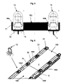
- FIG. 5 A floor panel 180 with integrated lashing point channels 180A and 180B is shown in FIG Fig. 5 in a cross-sectional view and in Fig. 6 shown in a perspective view.
- the floor panel 180 can be fastened directly to the aircraft structure 4 via fastening means 32, wherein preferably the lashing points 10 are provided with their base body 14 for connection to the structure 4. A direct load transfer into the structure 4 without further fastening or screw connections also acting on the floor plate 180 loads is thus achieved.
- the lashing devices 10 are preferably over lower and lateral Attachment possibilities 32 and 41 in the lashing point channels 180A and 180B attached.
- Fig. 5 A floor panel 180 with integrated lashing point channels 180A and 180B is shown in FIG Fig. 5 in a cross-sectional view and in Fig. 6 shown in a perspective view.
- the floor panel 180 can be fastened directly to the aircraft structure 4 via fastening means 32, wherein preferably the lashing points 10 are provided with their base body 14 for connection to the structure 4. A direct load transfer into
- the floor element 180 can be seen in a perspective view, wherein it can be seen that a plurality of successively arranged floor elements 180 and 180 'form a walkable floor area 2 and a longitudinal section with continuous lashing point channels 180A, 180A' and 180B, 180B '.
- a connection of the floor elements 180 and 180 ' can advantageously also be effected by means of the lashing devices 10.
- a plurality of lashing point channels (180A, 180A ', 180B, 180B') arranged one behind the other can advantageously form a guide for a warm air flow for heating the elements, such as lashing devices (10), load receptacles (30) or similar components, which also underlines the functionality of the freight loading system guaranteed extreme cold conditions.
- load receiving adapter 30 and adapter plates 33 which have a commonly known mounting profile (also referred to as seat rail profile) and which are suitable for connection of other components.
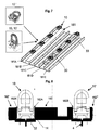
- a bottom member 181 having a plurality of integrated side-by-side channels 181A-181E is shown.
- the channels 181A and 181D are designed as lashing point channels and are provided for receiving lashing devices 10 or, as described in more detail in the preceding figures, for receiving adapter plates 33, load receiving adapter 30 or similar interface elements.
- the adjacently located channels 181B, 181C or 181E may receive further functional or interface elements.
- a narrow portion of a floor panel (tread surface) 2 is provided between the channel 181A and the channel 181B.
- Fig. 8 is one to Fig. 5 modified embodiment of a bottom plate 182 with integrated Zurrteilkanälen 182A and 182B shown.
- the bottom plate 182 is formed in the side regions so that the integrated lashing member channels 182A and 182B respectively form half of a complete lashing point channel.
- Each two adjacent bottom plates 182 and 182 'thus form a complete lashing point channel.
- two base plates 182 and 182 ' can be fastened to the structure 4 at the same time by means of fastening elements 32 via the base body 14 of the lashing device 10.
- the attachment of the bottom plates is simplified and a load introduction of the loads occurring on the bottom plate directly, without an additional sterbefest Trent can be done in the structure.
- the flexibility and the variety of possible applications of the device 18 or: 180 or 181 or 182 according to the invention as an interface for loads in a cargo hold floor of an aircraft is shown.
- FIGS. 9 to 11 show possible embodiments of lashing devices 10 as an integral part of the lashing point channel 18.
- the lashing device 10 includes a lashing element 11, which preferably has a rotated by 90 ° -D-shape. With the D-shape, an extension of the arc in two end portions 12 and 13 is achieved, which are designed for connection to a base body 14.
- the end portions 12 and 13 are each provided with transverse bores 15 through which a connecting pin 16 is inserted in each case.
- the connecting pins 16 are preferably mounted on the base body 14.
- the lashing element 11 is thus pivotable about a pivot axis 17 and can be pivoted when not in use in a horizontal position.
- the return spring also prevents vibration of the transport vibration and rattling of the lashing element.
- the main body 14 is at the as lashing points 3 (see Fig. 1 ) defined positions within the lashing point channel 18 or 180A, 180B, 181A and 181D or 182A, 182B shown in the previous figures.
- the main body 14 has fastening bores 19, by means of fastening means 32 a connection to the aircraft structure 4, preferably as attachment to a bulkhead, takes place.
- the lashing point channel 18 has corresponding through holes.
- lateral fastening bores 20 are furthermore arranged in order to be able to connect to the channel side walls 36.
- free grooves 21 are provided, which has a bridge-shaped design and is provided as a water and dirt drain.
- Liquids such as dirty water can thus easily drain within the lashing point channel. Easy cleaning of the corresponding lashing point channel and the lashing device 10 is possible by the structural design with large water drainage and air flow openings. Likewise, a guide for a hot air flow for heating the elements is made possible to maintain a functionality of the cargo loading system even under extreme cold conditions.
- An essential component of the main body 14 is a central receptacle 23, which may be preferably round, square or rectangular.
- the receiving opening 23 is provided as an alternative to fix components that can not be fastened by means of the lashing element 11 in the cargo deck.
- large static forces and moments can be absorbed in all directions.
- the receiving opening 23 is rectangular in shape and provided with an additional transverse bore 24. Through the transverse bore 24, a component 31 to be fixed within the receiving opening 23 can be secured by means of a locking bolt 25 (see also FIG Fig. 11 ). In this way, additional forces and moments can be absorbed via the locking bolt 25.
- Another mounting surface 26 is provided to allow with conventional mounting options recording and mounting of eg cover or adapter plates.
- threaded holes 27 are arranged on the mounting surface 26 as mounting options.
- the lashing element 11 is to be pivoted until the receiving opening is freely accessible or by a return spring 39, for example between the base body 14, connecting pin 16 and lashing element 11 is automatically taken a horizontal position when not in use of the lashing element 11.
- a lashing device 10 'in a second embodiment In a two-sided view, a lashing device 10 'in a second embodiment can be seen.
- Fig. 11 1 is a perspective view of a lashing device 10 "in a third embodiment Fig. 10 However, here are missing the lateral mounting holes 20 and located on the underside of the base 14 "free grooves 21st
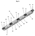
- FIGS. 12 to 16 Devices according to the invention - here in the form of a lashing point channel 18 - are shown in different construction variants. At least one lashing device 10 is arranged as an integral part of the lashing point channel 18 at regular intervals.
- adapter plates 33 can preferably be fastened directly to the base body 14 or to the aircraft structure through the base body 14.
- the adapter plates 33 can be used in accordance with the intended use for fastening or mounting a wide variety of systems or components.
- the adapter plates should have a recurring attachment profile 34.
- a plurality of adapter plates 33 are provided with a seat rail profile 34 known from civil aviation.
- This mounting profile can be incorporated directly into the adapter plates or connected as an independent component with the adapter plate or integrated into this, preferably screwed.
- a seat rail profile 34 is formed as a dovetail profile with Einrastlöchem at a distance of one inch.
- connection options for seats (in use for passenger transport) or for components from a freight loading system such as locking elements 8, additional roller conveyors 6, attachment of guide rails 7, etc ..
- locking elements 8 is detailed in the Fig. 16 shown.
- the adapter plates 33 can also be replaced by geometrically simple plates as cover plates for the unused areas of the lashing point channel 18. They are preferably attached directly to the mounting surface 26 of the lashing device 10 and / or on Zurrrioskanal 18.
- additional load receiving adapter 30 are integrated between the lashing devices in the lashing point channel 18 or connected directly to the channel side walls 36.
- cover plates or adapter plates can rest in addition to the Zurrvorraumetzlager lake 26 and be attached to it to accommodate greater loads and forces and to forward to the structure can.
- the adapter plates 33 and possibly also the cover plates (not shown) water inlet slots 28 and drain openings 29 have (see FIGS. 12 to 15 ).
- surface water or dirty water can run into the lashing point channel 18 and be drained there in the channel longitudinal direction. With the use of the channel 18 as a drainage system, it is achieved that no stagnant water remains in the system and thus the corrosion behavior is improved.
- a two-sided use of the adapter plates 33 can also be realized.
- the plates 33 on one side a mounting option, for example, the seat rail profile 34.
- the plates 33 are reversed to protect the interface from contamination and mechanical damage. For example, when driving on the aircraft deck and thus also the lashing point channel 18 with heavy vehicles, the protection of the interfaces is necessary.
- the receiving opening 23 of the lashing device 10 as an interface for receiving other installations and systems, such as medical care facilities, stretchers, seats, guide rails provided.
- an interface element 31 is shown, which is fixed within the receiving opening 23 by means of the locking bolt 25.
- the lashing device 10 with the functions of a lashing point and a receptacle 23 in combination with adapter plates 33 and / or load receiving adapters 30 can be integrated in the lashing point channel 18 a multifunctional and flexible adaptation of the cargo deck to the transport tasks to be performed guarantee. It is evident in all representations that 33 recesses 35 are provided for folding over the lashing element 11 in the corresponding adjacent adapter plates, in order to achieve a countersinking of the element 11 without disturbing transitions and thus a flat bottom.
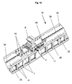
- Fig. 16 It is shown how to an adapter plate 33, a further component or a functional element can be attached.
- the functional element shown here is designed as a locking element 8 and is fixed in the longitudinal direction of the lashing point channel 18 in the seat rail profile 34 of an adapter plate 33.
- the fastening bolts 40 were inserted and locked in the seat rail profile.
- Such quick-release fasteners are known from civil aircraft, among other things for attaching seats. It is also possible to use other conventional fastening methods on the adapter plate 33 instead of the connection Wegschienenprofil- fastening bolts.
- With the locking element 8, the locking of standard containers / pallets is possible, which further improves the possible use of freight transport.
Landscapes
- Engineering & Computer Science (AREA)
- Mechanical Engineering (AREA)
- Aviation & Aerospace Engineering (AREA)
- Transportation (AREA)
- Connection Of Plates (AREA)
- Floor Finish (AREA)
- Pallets (AREA)
- Packaging Of Machine Parts And Wound Products (AREA)
- Packages (AREA)
- Package Frames And Binding Bands (AREA)
- Ship Loading And Unloading (AREA)
- Connector Housings Or Holding Contact Members (AREA)
Applications Claiming Priority (2)
| Application Number | Priority Date | Filing Date | Title |
|---|---|---|---|
| DE10324648A DE10324648B4 (de) | 2003-05-30 | 2003-05-30 | Vorrichtung zur Aufnahme von Zurrvorrichtungen für ein Frachtladesystem eines Transportmittels, insbesondere eines Flugzeuges |
| EP04012591A EP1481894B1 (fr) | 2003-05-30 | 2004-05-27 | Canal comprenant des points d'arrimage pour cargaison |
Related Parent Applications (2)
| Application Number | Title | Priority Date | Filing Date |
|---|---|---|---|
| EP04012591A Division EP1481894B1 (fr) | 2003-05-30 | 2004-05-27 | Canal comprenant des points d'arrimage pour cargaison |
| EP04012591.6 Division | 2004-05-27 |
Publications (2)
| Publication Number | Publication Date |
|---|---|
| EP2052969A1 true EP2052969A1 (fr) | 2009-04-29 |
| EP2052969B1 EP2052969B1 (fr) | 2010-07-28 |
Family
ID=33103656
Family Applications (2)
| Application Number | Title | Priority Date | Filing Date |
|---|---|---|---|
| EP04012591A Expired - Lifetime EP1481894B1 (fr) | 2003-05-30 | 2004-05-27 | Canal comprenant des points d'arrimage pour cargaison |
| EP09000709A Expired - Lifetime EP2052969B1 (fr) | 2003-05-30 | 2004-05-27 | Dispositif de réception de dispositifs d'amarrage pour un système de chargement de fret d'un moyen de transport, notamment d'un avion |
Family Applications Before (1)
| Application Number | Title | Priority Date | Filing Date |
|---|---|---|---|
| EP04012591A Expired - Lifetime EP1481894B1 (fr) | 2003-05-30 | 2004-05-27 | Canal comprenant des points d'arrimage pour cargaison |
Country Status (5)
| Country | Link |
|---|---|
| US (1) | US7214015B2 (fr) |
| EP (2) | EP1481894B1 (fr) |
| JP (1) | JP4486848B2 (fr) |
| AT (1) | ATE421457T1 (fr) |
| DE (3) | DE10324648B4 (fr) |
Families Citing this family (41)
| Publication number | Priority date | Publication date | Assignee | Title |
|---|---|---|---|---|
| DE10324649B4 (de) * | 2003-05-30 | 2007-05-24 | Airbus Deutschland Gmbh | Zurrpunktvorrichtung für ein Frachtladesystem eines Transportmittels, insbesondere eines Flugzeuges |
| DE10324650B4 (de) * | 2003-05-30 | 2005-04-28 | Airbus Gmbh | Zurrvorrichtung für ein Frachtladesystem eines Transportmittels, insbesondere eines Flugzeuges |
| DE102004014745B4 (de) * | 2004-03-22 | 2009-01-02 | Telair International Gmbh | Frachtdeck |
| US8057143B2 (en) * | 2004-10-05 | 2011-11-15 | Fontaine Trailer Company, Inc. | Trailer load securement system |
| RU2285637C2 (ru) * | 2005-01-11 | 2006-10-20 | Закрытое акционерное общество "Авиакомпания Волга-Днепр" | Грузовая кабина транспортного самолета преимущественно ан-124-100 |
| US8915684B2 (en) * | 2005-09-27 | 2014-12-23 | Fontaine Trailer Company, Inc. | Cargo deck |
| DE102006047238B4 (de) * | 2006-10-04 | 2010-01-14 | Airbus Deutschland Gmbh | Frachtladesystem mit Führungsschienen und mit einer Stelleinrichtung zum Ausrichten von Lagerteilen an toleranzbehafteten Strukturen |
| DE102006047237B4 (de) * | 2006-10-04 | 2010-01-14 | Airbus Deutschland Gmbh | Stelleinrichtung zum Ausrichten von Lagerteilen an toleranzbehafteten Strukturen |
| DE102006049075B4 (de) * | 2006-10-13 | 2009-12-17 | Airbus Deutschland Gmbh | Stelleinrichtung zum Ausrichten von Lagerteilen an toleranzbehafteten Strukturen |
| DE102007011619B4 (de) | 2007-01-22 | 2012-03-29 | Airbus Operations Gmbh | Bodenplatte zur Bildung einer Ladefläche in einem Frachtraum eines Luftfahrzeugs |
| DE102007052672B4 (de) * | 2007-11-05 | 2016-12-01 | Airbus Operations Gmbh | Rumpfzellenstruktur eines Flugzeugs zur vereinfachten Verlegung und Befestigung von Haltern zur Befestigung von Leitungen |
| DE102008004304A1 (de) * | 2008-01-15 | 2009-07-16 | Bayerische Motoren Werke Aktiengesellschaft | Kraftfahrzeug mit einem Laderaum |
| DE102008016104A1 (de) * | 2008-03-28 | 2009-10-08 | Airbus Deutschland Gmbh | Durchbrandsicherer Flugzeugrumpf |
| DE102009002745B4 (de) * | 2009-04-30 | 2013-10-31 | Airbus Operations Gmbh | Befestigungsanordnung für einen Frachtraumboden eines Flugzeuges und Flugzeug mit einer solchen Befestigungsanordnung |
| JP5095673B2 (ja) * | 2009-04-30 | 2012-12-12 | 芦森工業株式会社 | 車両の荷物保持装置 |
| US8075232B2 (en) * | 2009-05-05 | 2011-12-13 | Sierra Pacific Engineering And Products | System and method for securing cargo to a load bearing surface |
| DE102009003278B4 (de) * | 2009-05-20 | 2013-10-31 | Airbus Operations Gmbh | Befestigungsanordnung für einen Frachtraumboden eines Flugzeuges und Flugzeug mit einer solchen Befestigungsanordnung |
| US8424803B2 (en) | 2009-05-20 | 2013-04-23 | Airbus Operations Gmbh | Attachment arrangement for a cargo compartment floor of an aircraft and aircraft with an attachment arrangement of this type |
| US7651305B1 (en) * | 2009-06-10 | 2010-01-26 | The United States Of America As Represented By The Secretary Of The Navy | Retractable fitting |
| WO2011009474A1 (fr) * | 2009-07-21 | 2011-01-27 | Telair International Gmbh | Élément de plancher destiné au pont de chargement dun avion |
| EP2507128B1 (fr) | 2009-11-30 | 2014-01-08 | Telair International GmbH | Plancher de soute d'avion, element fonctionnel a integrer dans un plancher de soute, element de guidage lateral, dispositif de fixation permettant d'induire un effort de traction et dispositif permettant de larguer des elements de cargaison |
| DE202010008209U1 (de) * | 2010-08-03 | 2011-12-23 | Ulf Deisenroth | Sicherungssystem für Fahrzeuge, insbesondere Hubschrauber, die mit Auskleidungsmaterial ausgestattet sind |
| CN102951301A (zh) * | 2011-08-30 | 2013-03-06 | 中国民航机场建设集团公司 | 一种系留飞机用地锚系统 |
| DE102012005353A1 (de) | 2012-03-16 | 2013-09-19 | Airbus Operations Gmbh | Flugzeugrumpfstruktur mit Querprofilen und Fachwerkstruktur |
| US20140137724A1 (en) * | 2012-10-19 | 2014-05-22 | Sikorsky Aircraft Corporation | Structural ballistic protection panel |
| DE102013111408B3 (de) * | 2013-09-26 | 2015-01-22 | Telair International Gmbh | Verzurreinrichtung |
| US9993669B2 (en) * | 2015-06-10 | 2018-06-12 | D B Industries, Llc | D-ring keeper assembly |
| DE102015211295B4 (de) * | 2015-06-18 | 2022-06-09 | Bos Gmbh & Co. Kg | Vorrichtung zum Sichern von Ladegut in einem Laderaum eines Kraftfahrzeugs |
| US9908610B2 (en) * | 2016-01-28 | 2018-03-06 | The Boeing Company | Aircraft cargo handling system articulating ball mat |
| US10926115B2 (en) * | 2016-09-26 | 2021-02-23 | The Boeing Company | Fall protection apparatus and method |
| US11401023B2 (en) * | 2019-01-11 | 2022-08-02 | The Boeing Company | Aircraft cargo floor architecture and method of modifying the aircraft cargo floor architecture |
| EP3921218B1 (fr) * | 2019-02-05 | 2025-04-23 | MSI Defense Solutions, LLC | Système de pont commun configurable |
| US11643209B1 (en) * | 2019-09-30 | 2023-05-09 | United States Of America As Represented By The Secretary Of The Air Force | Aircraft loading system |
| CN112357052B (zh) * | 2020-11-20 | 2022-05-17 | 中国直升机设计研究所 | 一种通用型直升机客货舱多功能座椅 |
| DE102021104500A1 (de) * | 2021-02-25 | 2022-08-25 | Premium Aerotec Gmbh | Zweiteilige Montageschiene für ein Fahrzeug |
| EP4067225A1 (fr) * | 2021-04-02 | 2022-10-05 | Telair International GmbH | Module de plancher faisant partie intégrante, système de chargement de fret, élément de verrouillage, ainsi que procédé de mise à niveau d'un pont des passagers à un pont à fret |
| US20230322387A1 (en) * | 2022-03-25 | 2023-10-12 | Goodrich Corporation | Tie down for cargo handling systems |
| CN114919750B (zh) * | 2022-06-28 | 2023-04-18 | 中国人民解放军火箭军工程设计研究院 | 应用于直升机的重型货物地空转载运输系统 |
| CN114906329B (zh) * | 2022-06-28 | 2023-04-18 | 中国人民解放军火箭军工程设计研究院 | 应用于直升机的牵引式重型物资装卸载及运输保障系统 |
| CN118270050A (zh) * | 2024-03-30 | 2024-07-02 | 中船吉海(昆山)高科有限公司 | 一种平车运输轮式、履带式装备的加固方法 |
| JP7745942B1 (ja) * | 2025-04-28 | 2025-09-30 | Joyfic株式会社 | コンテナ |
Citations (4)
| Publication number | Priority date | Publication date | Assignee | Title |
|---|---|---|---|---|
| US3241500A (en) | 1963-02-26 | 1966-03-22 | Simpson Barclay | Load holding devices |
| FR2745260A1 (fr) * | 1996-02-28 | 1997-08-29 | Airbus Ind | Systeme et procede de conversion rapide et reversible d'un avion entre une configuration passagers et une configuration fret |
| EP0881144A1 (fr) * | 1997-05-28 | 1998-12-02 | Telair International GmbH | Dispositif de montage pour un unité d'entraínement de rouleaux |
| EP0894713A1 (fr) | 1997-07-29 | 1999-02-03 | AAR Corp. | Système polyvalent d'arrimage pour charge |
Family Cites Families (19)
| Publication number | Priority date | Publication date | Assignee | Title |
|---|---|---|---|---|
| US2605064A (en) * | 1947-07-10 | 1952-07-29 | Frank L Davis | Cargo securing system |
| US3693920A (en) | 1970-12-09 | 1972-09-26 | Boeing Co | Retractable cargo securing device |
| DE3232234A1 (de) * | 1982-08-30 | 1984-05-24 | Messerschmitt-Bölkow-Blohm GmbH, 8012 Ottobrunn | Schnellspannelement fuer schienenprofile |
| US4907921A (en) * | 1984-01-03 | 1990-03-13 | A. L. Hansen Manufacturing Co. | Tie-down assembly |
| US4715754A (en) * | 1986-06-18 | 1987-12-29 | The United States Of America As Represented By The Secretary Of The Army | Tiedown assembly |
| US4850769A (en) * | 1987-06-08 | 1989-07-25 | James E. Irvin | Tie-down device |
| US4802572A (en) * | 1987-11-02 | 1989-02-07 | The Boeing Company | Aircraft cargo roller system |
| DE3943077A1 (de) * | 1989-12-27 | 1991-07-04 | Airbus Gmbh | Riegelelement zum arretieren von frachtstuecken |
| US5076745A (en) * | 1990-09-28 | 1991-12-31 | George Klein | Bulkhead and rail transport system |
| DE4102274C1 (fr) | 1991-01-26 | 1992-01-30 | Deutsche Airbus Gmbh, 2000 Hamburg, De | |
| EP0816224B1 (fr) * | 1996-07-05 | 2001-06-13 | Telair International GmbH | Elément fonctionnel monté dans le plancher d'un avion |
| DE19720224A1 (de) * | 1997-03-24 | 1998-10-01 | Telair Int Gmbh | Kugelmatte |
| DE19724941C2 (de) * | 1997-06-12 | 2001-05-10 | Telair Int Gmbh | Einbauvorrichtung für eine Rollenantriebseinheit |
| US6138975A (en) * | 1998-08-13 | 2000-10-31 | Kryptonite Corporation | Anchored tie-down ring |
| GB2346928B (en) * | 1998-11-24 | 2003-04-09 | Telair Int Gmbh | Latch element |
| US6374466B1 (en) * | 1999-10-26 | 2002-04-23 | Vincent I. Macias | Spring loaded and latchable stake pocket tie down apparatus |
| US6533512B2 (en) * | 2001-05-10 | 2003-03-18 | Chia-Sheng Lin | Quick-detachable device for attaching ropes thereto |
| DE10324650B4 (de) * | 2003-05-30 | 2005-04-28 | Airbus Gmbh | Zurrvorrichtung für ein Frachtladesystem eines Transportmittels, insbesondere eines Flugzeuges |
| DE10324649B4 (de) * | 2003-05-30 | 2007-05-24 | Airbus Deutschland Gmbh | Zurrpunktvorrichtung für ein Frachtladesystem eines Transportmittels, insbesondere eines Flugzeuges |
-
2003
- 2003-05-30 DE DE10324648A patent/DE10324648B4/de not_active Expired - Fee Related
-
2004
- 2004-05-27 EP EP04012591A patent/EP1481894B1/fr not_active Expired - Lifetime
- 2004-05-27 DE DE502004008894T patent/DE502004008894D1/de not_active Expired - Lifetime
- 2004-05-27 DE DE502004011456T patent/DE502004011456D1/de not_active Expired - Lifetime
- 2004-05-27 AT AT04012591T patent/ATE421457T1/de not_active IP Right Cessation
- 2004-05-27 EP EP09000709A patent/EP2052969B1/fr not_active Expired - Lifetime
- 2004-05-28 JP JP2004159038A patent/JP4486848B2/ja not_active Expired - Fee Related
- 2004-06-01 US US10/859,443 patent/US7214015B2/en not_active Expired - Lifetime
Patent Citations (4)
| Publication number | Priority date | Publication date | Assignee | Title |
|---|---|---|---|---|
| US3241500A (en) | 1963-02-26 | 1966-03-22 | Simpson Barclay | Load holding devices |
| FR2745260A1 (fr) * | 1996-02-28 | 1997-08-29 | Airbus Ind | Systeme et procede de conversion rapide et reversible d'un avion entre une configuration passagers et une configuration fret |
| EP0881144A1 (fr) * | 1997-05-28 | 1998-12-02 | Telair International GmbH | Dispositif de montage pour un unité d'entraínement de rouleaux |
| EP0894713A1 (fr) | 1997-07-29 | 1999-02-03 | AAR Corp. | Système polyvalent d'arrimage pour charge |
Also Published As
| Publication number | Publication date |
|---|---|
| EP1481894A2 (fr) | 2004-12-01 |
| DE502004011456D1 (de) | 2010-09-09 |
| DE10324648B4 (de) | 2008-01-10 |
| US20040258498A1 (en) | 2004-12-23 |
| EP2052969B1 (fr) | 2010-07-28 |
| EP1481894B1 (fr) | 2009-01-21 |
| JP4486848B2 (ja) | 2010-06-23 |
| JP2004359227A (ja) | 2004-12-24 |
| US7214015B2 (en) | 2007-05-08 |
| DE10324648A1 (de) | 2004-12-30 |
| EP1481894A3 (fr) | 2004-12-08 |
| ATE421457T1 (de) | 2009-02-15 |
| DE502004008894D1 (de) | 2009-03-12 |
Similar Documents
| Publication | Publication Date | Title |
|---|---|---|
| EP2052969B1 (fr) | Dispositif de réception de dispositifs d'amarrage pour un système de chargement de fret d'un moyen de transport, notamment d'un avion | |
| EP1646556B1 (fr) | Plate-forme de transport de marchandises destinee a recevoir le chargement a l'interieur de l'espace de transport de marchandises d'un avion | |
| EP1481893B1 (fr) | Système d'arrimage pour fret | |
| EP0496974B1 (fr) | Element de verrouillage | |
| DE102007011611A1 (de) | Befestigungsanordnung für Verzurrbügel in einem Frachtraumboden eines Flugzeugs | |
| WO2005077755A9 (fr) | Plancher de la soute d'avions | |
| DE69801225T2 (de) | Fahrgestell | |
| DE102018123531B4 (de) | Verfahren zum Installieren von Systemkomponenten in einem Abschnitt eines Flugzeugrumpfs | |
| EP1481844B1 (fr) | Système d'arrimage pour cargaison | |
| WO2016150891A1 (fr) | Module de plancher d'une soute d'aéronef | |
| DE102018108950B3 (de) | Frachtdeck eines Flugzeugs und Verfahren zur Herstellung eines Bodenmoduls | |
| DE102017220378A1 (de) | Bodenbaugruppe mit monolithischem Bodenelement sowie Luftfahrzeugbereich und Luftfahrzeug mit einer Bodenbaugruppe | |
| DE19805284B9 (de) | Bodenbaugruppe für Fahrzeuge | |
| EP0827906B1 (fr) | Elément de verrouillage pour un système de blocage des colis dans une soute à fret d'avion | |
| DE102006007469A1 (de) | Fußbodenaufbau in einem Flugzeug mit durchlaufenden Fußbodenplatten | |
| DE102015120515A1 (de) | Modulares Schienensystem zum Befestigen von Einrichtungsgegenständen an einem Fußboden einer Fahrzeugkabine | |
| DE102007020589A1 (de) | Nutzfahrzeug, Boden für ein Nutzfahrzeug, Verfahren zur Herstellung eines Nutzfahrzeugs | |
| DE102010036515A1 (de) | Fußboden für Fahrzeuge sowie Bausatz für einen Fußboden mit einer Fußbodenschiene mit einem Doppelkammer-Hohlprofil | |
| DE102015117571B3 (de) | Bodenmodul eines Flugzeugfrachtraumes | |
| DE102019132513A1 (de) | Bodenelement sowie Luftfahrzeugbereich und Luftfahrzeug mit einem Bodenelement | |
| EP4067225A1 (fr) | Module de plancher faisant partie intégrante, système de chargement de fret, élément de verrouillage, ainsi que procédé de mise à niveau d'un pont des passagers à un pont à fret | |
| EP3129285B1 (fr) | Système de bâti de siège d'avion | |
| DE102021115146B3 (de) | Integrales Bodenmodul, Frachtladesystem, Riegelelement sowie Verfahren zum Umrüsten eines Passagierdecks in ein Frachtdeck | |
| DE102007062747A1 (de) | Bodenplatte zur Abdeckung eines Fußbodengerüstes in einem Flugzeug | |
| DE102009002745B4 (de) | Befestigungsanordnung für einen Frachtraumboden eines Flugzeuges und Flugzeug mit einer solchen Befestigungsanordnung |
Legal Events
| Date | Code | Title | Description |
|---|---|---|---|
| PUAI | Public reference made under article 153(3) epc to a published international application that has entered the european phase |
Free format text: ORIGINAL CODE: 0009012 |
|
| AC | Divisional application: reference to earlier application |
Ref document number: 1481894 Country of ref document: EP Kind code of ref document: P |
|
| AK | Designated contracting states |
Kind code of ref document: A1 Designated state(s): AT BE BG CH CY CZ DE DK EE ES FI FR GB GR HU IE IT LI LU MC NL PL PT RO SE SI SK TR |
|
| 17P | Request for examination filed |
Effective date: 20091029 |
|
| AKX | Designation fees paid |
Designated state(s): DE FR GB IT SE |
|
| GRAP | Despatch of communication of intention to grant a patent |
Free format text: ORIGINAL CODE: EPIDOSNIGR1 |
|
| GRAS | Grant fee paid |
Free format text: ORIGINAL CODE: EPIDOSNIGR3 |
|
| GRAA | (expected) grant |
Free format text: ORIGINAL CODE: 0009210 |
|
| AC | Divisional application: reference to earlier application |
Ref document number: 1481894 Country of ref document: EP Kind code of ref document: P |
|
| AK | Designated contracting states |
Kind code of ref document: B1 Designated state(s): DE FR GB IT SE |
|
| REG | Reference to a national code |
Ref country code: GB Ref legal event code: FG4D Free format text: NOT ENGLISH |
|
| REF | Corresponds to: |
Ref document number: 502004011456 Country of ref document: DE Date of ref document: 20100909 Kind code of ref document: P |
|
| PG25 | Lapsed in a contracting state [announced via postgrant information from national office to epo] |
Ref country code: SE Free format text: LAPSE BECAUSE OF FAILURE TO SUBMIT A TRANSLATION OF THE DESCRIPTION OR TO PAY THE FEE WITHIN THE PRESCRIBED TIME-LIMIT Effective date: 20100728 |
|
| PG25 | Lapsed in a contracting state [announced via postgrant information from national office to epo] |
Ref country code: IT Free format text: LAPSE BECAUSE OF FAILURE TO SUBMIT A TRANSLATION OF THE DESCRIPTION OR TO PAY THE FEE WITHIN THE PRESCRIBED TIME-LIMIT Effective date: 20100728 |
|
| PLBE | No opposition filed within time limit |
Free format text: ORIGINAL CODE: 0009261 |
|
| STAA | Information on the status of an ep patent application or granted ep patent |
Free format text: STATUS: NO OPPOSITION FILED WITHIN TIME LIMIT |
|
| 26N | No opposition filed |
Effective date: 20110429 |
|
| REG | Reference to a national code |
Ref country code: DE Ref legal event code: R097 Ref document number: 502004011456 Country of ref document: DE Effective date: 20110429 |
|
| REG | Reference to a national code |
Ref country code: FR Ref legal event code: PLFP Year of fee payment: 13 |
|
| REG | Reference to a national code |
Ref country code: FR Ref legal event code: PLFP Year of fee payment: 14 |
|
| REG | Reference to a national code |
Ref country code: FR Ref legal event code: PLFP Year of fee payment: 15 |
|
| PGFP | Annual fee paid to national office [announced via postgrant information from national office to epo] |
Ref country code: DE Payment date: 20190521 Year of fee payment: 16 |
|
| PGFP | Annual fee paid to national office [announced via postgrant information from national office to epo] |
Ref country code: FR Payment date: 20190523 Year of fee payment: 16 |
|
| PGFP | Annual fee paid to national office [announced via postgrant information from national office to epo] |
Ref country code: GB Payment date: 20190521 Year of fee payment: 16 |
|
| REG | Reference to a national code |
Ref country code: DE Ref legal event code: R119 Ref document number: 502004011456 Country of ref document: DE |
|
| GBPC | Gb: european patent ceased through non-payment of renewal fee |
Effective date: 20200527 |
|
| PG25 | Lapsed in a contracting state [announced via postgrant information from national office to epo] |
Ref country code: FR Free format text: LAPSE BECAUSE OF NON-PAYMENT OF DUE FEES Effective date: 20200531 Ref country code: GB Free format text: LAPSE BECAUSE OF NON-PAYMENT OF DUE FEES Effective date: 20200527 |
|
| PG25 | Lapsed in a contracting state [announced via postgrant information from national office to epo] |
Ref country code: DE Free format text: LAPSE BECAUSE OF NON-PAYMENT OF DUE FEES Effective date: 20201201 |