EP2052976B1 - Dispositif de fabrication de sachets d'infusion - Google Patents
Dispositif de fabrication de sachets d'infusion Download PDFInfo
- Publication number
- EP2052976B1 EP2052976B1 EP07020643A EP07020643A EP2052976B1 EP 2052976 B1 EP2052976 B1 EP 2052976B1 EP 07020643 A EP07020643 A EP 07020643A EP 07020643 A EP07020643 A EP 07020643A EP 2052976 B1 EP2052976 B1 EP 2052976B1
- Authority
- EP
- European Patent Office
- Prior art keywords
- infusion
- bag
- cutting
- cutting tool
- chamber
- Prior art date
- Legal status (The legal status is an assumption and is not a legal conclusion. Google has not performed a legal analysis and makes no representation as to the accuracy of the status listed.)
- Active
Links
Images


Classifications
-
- B—PERFORMING OPERATIONS; TRANSPORTING
- B65—CONVEYING; PACKING; STORING; HANDLING THIN OR FILAMENTARY MATERIAL
- B65B—MACHINES, APPARATUS OR DEVICES FOR, OR METHODS OF, PACKAGING ARTICLES OR MATERIALS; UNPACKING
- B65B69/00—Unpacking of articles or materials, not otherwise provided for
- B65B69/0008—Opening and emptying bags
-
- B—PERFORMING OPERATIONS; TRANSPORTING
- B65—CONVEYING; PACKING; STORING; HANDLING THIN OR FILAMENTARY MATERIAL
- B65B—MACHINES, APPARATUS OR DEVICES FOR, OR METHODS OF, PACKAGING ARTICLES OR MATERIALS; UNPACKING
- B65B29/00—Packaging of materials presenting special problems
- B65B29/02—Packaging of substances, e.g. tea, which are intended to be infused in the package
- B65B29/028—Packaging of substances, e.g. tea, which are intended to be infused in the package packaging infusion material into filter bags
-
- B—PERFORMING OPERATIONS; TRANSPORTING
- B65—CONVEYING; PACKING; STORING; HANDLING THIN OR FILAMENTARY MATERIAL
- B65B—MACHINES, APPARATUS OR DEVICES FOR, OR METHODS OF, PACKAGING ARTICLES OR MATERIALS; UNPACKING
- B65B57/00—Automatic control, checking, warning, or safety devices
- B65B57/10—Automatic control, checking, warning, or safety devices responsive to absence, presence, abnormal feed, or misplacement of articles or materials to be packaged
- B65B57/14—Automatic control, checking, warning, or safety devices responsive to absence, presence, abnormal feed, or misplacement of articles or materials to be packaged and operating to control, or stop, the feed of articles or material to be packaged
-
- B—PERFORMING OPERATIONS; TRANSPORTING
- B65—CONVEYING; PACKING; STORING; HANDLING THIN OR FILAMENTARY MATERIAL
- B65B—MACHINES, APPARATUS OR DEVICES FOR, OR METHODS OF, PACKAGING ARTICLES OR MATERIALS; UNPACKING
- B65B59/00—Arrangements to enable machines to handle articles of different sizes, to produce packages of different sizes, to vary the contents of packages, to handle different types of packaging material, or to give access for cleaning or maintenance purposes
- B65B59/04—Machines constructed with readily-detachable units or assemblies, e.g. to facilitate maintenance
Definitions
- the present invention relates to an apparatus for making infusion bags having an infusion material supply for supplying infusible material and a bag material supply for supplying bag material surrounding the infusion material, which is transformed into filled infusion bags in the device including a predetermined amount of infusible material.
- the previously known device has a conveying path for discharging the infusion bags and a switch for diverting defective infusion bags, which is followed by a cutting device and a conveyor for recovering and returning the infusible material faulty infusion bag to the infusion material supply.
- the present invention relates to the batch-return of infillable material from initially produced defective infusion bags which prove defective during production.
- defective infusion bags have always been diverted in a diverter provided in the rear of the infusion bag making apparatus and activated by a signal generated by one or more sensors associated with the infusion bag making apparatus and which faulty infusion bag detects.
- the defective infusion bags are comminuted at a separate processing station and the bag material is separated from the infusible material. The latter is fed back to the apparatus for producing infusion bags.
- the apparatus for producing infusion bags there is a need to be able to trace food back to batches. This also applies to infusible bags, especially tea bags and so it is with the EP 1 813 535 has proposed to associate the device for the production of infusion bags with a device for recovering tea from malformed teabags.
- the known device has a cutting device with cutting cylinders, which are arranged on at least two parallel, rotationally driven shafts and mesh with each other such that a first radially encircling edge of a cutting cylinder, which is mounted on a shaft, as a cutting edge axially against a radially encircling edge of another cylinder which is arranged on the other shaft, acting as a counter-blade shearing.
- a second radially encircling, axially in an opposite direction to the first facing edge of the cylinder is provided as a second cutting edge of this cylinder axially against a radially encircling edge of a third cylinder on another shaft. Due to this special design of the cutting unit, the defective infusion bag should be cut into strips with its bag material. The cutting unit is followed by a screening plant in which the bag material is separated from the tea.
- intermeshing cutting cylinders require compliance with relatively accurate tolerances. Moreover, cutting the bag material into parallel strips does not prevent the formation of pockets in which infusible material is trapped. Accordingly, in the prior art device further measures, such as a vibrating chute are provided to separate the cut bag material from the infusible material.
- the present invention provides an apparatus having the features of claim 1.
- the infusible material is already separated from the bag material in the cutting device.
- the cutting device has two separate outlets, wherein one outlet is prepared such that the infusible material is conveyed out of the cutting chamber through the latter, while the other outlet is prepared so that bag material leaves the cutting chamber through this outlet.
- the principle of air classification is essentially used.
- the flow required for this which separates the relatively large-area shreds of the bag material from the relatively small granular infusion material, is preferably generated by the rotation of the rotating cutting tool.
- the flow entrains the shreds of the bag material which, after opening the flap in the flow, are discharged from the cutting chamber.
- the bag material outlet is provided in extension of a peripheral wall surrounding the cutting tool and in front of the latter in the direction of rotation of the cutting tool, so that the flow generated by the cutting tool flows against the bag material outlet.
- the axis of rotation of the cutting tool substantially in the horizontal and to provide the flap above the axis of rotation and in the direction of rotation of the cutting tool, for example, a knife and in extension of a circumferentially surrounding the cutting tool side wall of the cutting chamber.
- the bag material is cut into shreds by the rotating cutting tool and swirled up by the rotation of the cutting tool and to an outlet, which usually does not reach the relatively small particles of the infusible material even with a rotation of the cutting tool. It has proven to be advantageous to rotate the cutting blade at a speed of between 1500 and 2500 revolutions per minute.
- the outlet for the bag material is kept closed until the infusible material has completely or almost completely dripped through the infusion material outlet, which may be formed by a sieve, for example, and has left the cutting chamber.
- the bag is first cut with the flap closed.
- the shredded bag material circulates with the rotating cutting tool in the cutting chamber, whereas the infusible material exits through a screen the cutting chamber located in the bottom of the cutting chamber, i. in the direction of gravity below the cutting tool.
- the flap is opened so that the shreds of the bag material can leave the cutting chamber. Thereafter, the flap is closed to prepare the cutting chamber for a new expected bag to be shredded in the cutting chamber.
- blower which is operable in response to a signal generated by a sensor detecting a faulty bag.
- This blower is associated with a collecting chamber for the blown-up infusion bag, which is upstream of the conveyor line and arranged above the cutting chamber.
- the collecting chamber is located in front of a plan view of the device of the conveyor line, ie before the same.
- the faulty infusion bag is accordingly blown away from the actual device for producing the infusion bag and removed from it.
- the defective bag thus removed from the conveying path passes by gravity into the cutting chamber, since the collecting chamber is arranged above the cutting chamber, ie the defective bag falls or slides into the cutting chamber.
- the collecting chamber preferably opens into the cutting chamber at approximately the same height as the bag material outlet, but is provided in the direction of rotation of the cutting tool on the opposite side relative to the flap, ie behind the cutting tool in the direction of rotation. This gives the possibility to generate by rotation of the cutting tool, a flow, which eventually in the collecting chamber Hanging segregated faulty infusion bag sucks into the cutting chamber.
- defective infusion bags usually fall into the cutting chamber solely by gravity.
- the blower and the collecting chamber are provided opposite each other, in such a way that between the conveyor line can be arranged.
- the cutting chamber is also provided.
- the return module has an independent machine housing, which stands on the floor and / or is carried by the machine housing, but in any case is connected to it.
- the module is designed so that also suitable for retrofitting existing devices for the production of infusion bags without appropriate return possibility of infusion material faulty infusion bag.
- Pneumatic delivery hoses are used to transport the infusion material from the cutting chamber to the infusion material supply on the one hand or the cut bag material to a collecting container. This can be formed for example by a conventional industrial vacuum cleaner.
- the present invention is provided between the blower and the collecting chamber a standing upright on the conveyor line infusion bag in the region of the switch leading guide rail.
- This guide rail is pivotally mounted and driven, in such a way that the guide rail pivots away on actuation of the blower from the conveyor line. In other words, the guide rail releases the lateral guidance of the infusion bag during a blow-out pulse, so that it can be separated from the conveyor line.
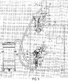
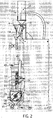
- FIGS. 1 and 2 show - partially schematically - an embodiment of an apparatus for producing infusion bags.
- the previously known device has an infusion material feed 2 comprising a funnel 4, which is arranged on the upper side of a machine housing 6 shown schematically.
- a pneumatic conveyor 8 with a feed hopper 10, which communicates via a conveyor pipe 12 with a memory 14 of a metering device 16 not further detailed.
- the machine housing 6 there are various parts of the system which metered via the infusion material supply 2 supplied infusible material, supplying portions of bag material, which are folded into an infusion bag and sealed.
- this production line is shown with broken lines star wheel 18, at the arms each an infusion bag clamped in the last process steps of the manufacturing process and through which the finished infusion bag is finally deposited on a conveyor line 20, via which the finished infusion bags are conveyed away.
- This conveyor line 20 extends substantially in the horizontal direction with an inclination of 45 ° to the vertical. The individual infusion bags are transported upright with their respective label on this conveyor line 20 upwards.
- this conveyor line 20 is located between a collecting chamber 22, which is arranged with respect to the machine housing 6 in front of the conveyor line 20, and provided near the machine housing 6 blow-out 24.
- the blow-out 24 is directed with its blow-out on the conveyor line, in such a way that an upright infusion bag receives a pulse transversely to the conveying direction of the conveying path 20 and enters the collecting chamber 22.
- the Blower 24 has an electromagnetic valve in front of which there is a constant supply of positive pressure air and which is opened to a signal from a number of sensors that check the teabag quality, indicating that a faulty infusion bag is passing through the blower 24.
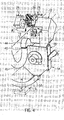
- a cutting chamber 26 in which a rotating cutting tool in the form of a knife 28 is provided with two opposing blades 30 ( FIG. 5 ).
- the knife 28 is circumferentially surrounded by a side wall 32 that extends substantially annularly around the knife 28.
- This outlet 36 for the bag material lies in the direction of rotation of the rotating blade 28 in front of it.
- the side wall 32 has a plurality of holes and is formed in the manner of a screen 38. Below the screen 38 is a collection space 40 for the infusible material of the defective infusion bag.
- FIG. 5 an infusion bag in the form of a tea bag 42 is also shown for size comparison of individual device parts with the tea bag 42 to be shredded.
- the bag material outlet 36 which is closable with a pivotable and driven flap 37, is covered by an exit bow 44 which initially deflects the flow within the bend 44 from the outlet 36 by 180 ° and has a neck 45 at its outlet. on which a waste conveyor hose 46 is attached, which leads to a collecting container with integrated suction device in the manner of an industrial vacuum cleaner 48.
- connection piece 50 for a flexible conveyor hose 52 for recovered tea which connects the collecting space 40 with the conveyor 8.
- FIGS. 1 and 2 can recognize the cutting chamber 26 and the blower 24 are formed with the associated collecting chamber 22 as part of a roller mounted on return module 54, which can be pushed up as a separate component to the machine housing 6.
- the blow-out device 24 is detachably connected thereto attached to the housing of the cutting chamber 26 and can be mounted after removal of the return module 54 between the conveyor line 20 and the machine housing 6.
- the machine control transmits the corresponding sensor signal to the blower device so that it opens a blowout pulse directed to the conveyor line 20 by opening the solenoid valve, if the corresponding faulty teabag Infusion bag passes the blow-out device.
- a lateral guide which delimits the conveying path 20 and is provided between the collecting chamber 22 and the conveying path 20, is pivoted upwards, so that the lateral guidance of the upright tea bag in the area of the blow-out device 24 is canceled.
- the thus-laterally irradiated tea bag is accordingly removed from the conveying path 20 and spent via the air blast via the collecting chamber 22.
- the separated tea bag 42 falls into the cutting chamber 26.
- teabag 42 lying on the screen 38 lying.
- the knife 28 is activated.
- the blades 30 disassemble the tea bag 42 including a label disposed thereon.
- the rotation of the blade 28 is adjusted so that the material forming the bag and the label is shredded.
- This material is swirled by the rotation of the blade 28 in the cutting chamber 26, whereas the tea falls through the screen 38 into the plenum 40 due to its lower engagement surface and relatively higher weight.
- the operating conditions and service life of the blade 28 are pre-set, such that sufficient tearing of the teabag 42 into small shreds is ensured and there is no fear that the teabag material will form pockets or the like in which significant amounts of tea may catch ,
- the flap 37 is opened.
- the rotating blade 28 acts as a fan which generates a stream of air flowing through the outlet 36, which also entrains the shreds of the divided bag material and the label and removes them via the exit sheet 44.
- the vacuum generated by the industrial vacuum cleaner 48 acts, which sucks the shreds through the waste conveyor hose 46.
- the tea located in the collecting space 40 is usually temporarily stored there until a certain number of tea bags have been cut in the cutting chamber 26.
- a sensor is assigned to the collecting space 40, which checks the fill level in the collecting space 40 and sends a signal for conveying the recovered tea to the infusion material feed 7.
- the pneumatic conveying device 8 is turned on to suck the tea material from the collecting space 40 via the delivery hose 52 to the infusion material supply 2.
- the tea falls over the feed hopper 10 and the obliquely downward conveying tube 12 into the memory 14 and is there for reuse.
- the present invention is intended to provide batched return of tea from defective infusion bags. Accordingly, in any case with a new batch, which is supplied via the main hopper 4 of the machine, the collecting space is completely emptied by operating the conveyor 8.
- the present invention is not limited to the embodiment shown.
- several cutting tools can be provided in the cutting chamber.
- knives and thread or other suitable cutting devices are conceivable that can cut the Aufgussbergmaterial.
- those are also conceivable, which are arranged movably, or in parts movable on a rotating cutting tool holder.
- the illustrated orientation of the axis of rotation of the cutting blade in the horizontal is merely an example.
- the knife can rotate about a vertical axis and fall, for example, in the axial direction in the cutting chamber.
- the two outlets for the infusion material on the one hand and the bag material on the other hand will usually continue to provide in the circumferential direction with respect to the direction of rotation of the cutting blade, so that the two materials can be discharged from the cutting chamber by the centrifugal force or flow.
- the cutting chamber may be sized to first collect a plurality of faulty infusion bags in the cutting chamber and only later to energize the cutting tool to separate the infusion material from the bag material.
Landscapes
- Engineering & Computer Science (AREA)
- Mechanical Engineering (AREA)
- Medical Preparation Storing Or Oral Administration Devices (AREA)
- Control And Other Processes For Unpacking Of Materials (AREA)
- Basic Packing Technique (AREA)
Claims (7)
- Dispositif pour fabriquer des sachets d'infusion, avec une amenée de matériau d'infusion (2) pour amener un matériau apte à infuser, et une amenée de matériau de sachet pour amener un matériau de sachet qui entoure le matériau d'infusion et qui est transformé dans le dispositif, en enfermant une quantité prédéfinie de matériau apte à infuser, en sachets d'infusion remplis (42), et avec une section de transport (20) pour évacuer les sachets d'infusion (42), et un aiguillage pour dévier les sachets d'infusion (42) défectueux, en aval duquel sont disposés un dispositif de coupe (26, 28) et un dispositif de transport (8, 52) pour récupérer et ramener jusqu'à l'amenée de matériau d'infusion (2) le matériau apte à infuser des sachets d'infusion (42) défectueux,
caractérisé en ce que le dispositif de coupe (26, 28) est constitué par un dispositif de coupe et de séparation (26, 28) qui fonctionne selon le principe de la séparation à air et qui comporte une chambre de coupe (26) avec un outil de coupe rotatif (28), une sortie de matériau d'infusion (38) et une sortie de matériau de sachet (36) apte à être fermée par un volet (37), un écoulement destiné à séparer le matériau de sachet du matériau d'infusion pouvant être produit dans le dispositif de coupe (26, 28). - Dispositif selon la revendication 1, caractérisé en ce que la sortie de matériau de sachet (36) est prévue dans le prolongement d'une paroi latérale (32) qui entoure l'outil de coupe (28) sur sa circonférence, et avant le dispositif de coupe (28), dans le sens de rotation de celui-ci.
- Dispositif selon la revendication 1 ou 2, caractérisé en ce que l'axe de rotation de l'outil de coupe (28) s'étend globalement à l'horizontale et le volet (37) est prévu au-dessus de l'axe de rotation et avant l'outil de coupe (28), dans le sens de rotation de celui-ci, et dans le prolongement d'une paroi latérale (32) qui entoure l'outil de coupe (28) sur sa circonférence.
- Dispositif selon l'une des revendications précédentes, caractérisé en ce que la sortie de matériau d'infusion (38) est formée par un tamis (38) qui laisse passer le matériau apte à infuser et en aval duquel, dans le sens de la gravité, est disposé un espace collecteur de matériau d'infusion (40).
- Dispositif selon l'une des revendications précédentes, caractérisé en ce que l'aiguillage comprend un dispositif d'évacuation par soufflage (24) qui est apte à être actionné en fonction d'un signal produit par au moins un capteur qui détecte un sachet (42) défectueux, et auquel est associée une chambre collectrice (22) pour le sachet d'infusion (42) évacué, qui est disposée en amont de la section de transport (20) et au-dessus de la chambre de coupe (26).
- Dispositif selon la revendication 5, caractérisé en ce que le dispositif d'évacuation par soufflage (24) et la chambre collectrice (22) sont disposés face à face en entourant la section de transport (20) et sont réalisés sous la forme d'une partie d'un module de retour (54) qui comprend la chambre de coupe (26) et qui est relié par l'intermédiaire de tuyaux de transport pneumatiques (46, 52) à l'amenée de matériau d'infusion (2), d'un côté, et à un collecteur de matériau de sachet d'infusion (48), de l'autre côté.
- Dispositif selon l'une des revendications précédentes, caractérisé en ce qu'il est prévu entre le dispositif d'évacuation par soufflage (24) et la chambre collectrice (22) un rail de guidage qui guide dans la zone de l'aiguillage le sachet (42) posé à la verticale sur la section de transport (20), et qui est monté pivotant et entraîné de manière à être éloigné de ladite section de transport (20) quand le dispositif d'évacuation par soufflage (24) est actionné.
Priority Applications (6)
| Application Number | Priority Date | Filing Date | Title |
|---|---|---|---|
| EP07020643A EP2052976B1 (fr) | 2007-10-22 | 2007-10-22 | Dispositif de fabrication de sachets d'infusion |
| AT07020643T ATE471870T1 (de) | 2007-10-22 | 2007-10-22 | Vorrichtung zur herstellung von aufgussbeuteln |
| PL07020643T PL2052976T3 (pl) | 2007-10-22 | 2007-10-22 | Urządzenie do wytwarzania torebek infuzyjnych |
| ES07020643T ES2346917T3 (es) | 2007-10-22 | 2007-10-22 | Dispositivo para la fabricacion de bolsas de infusion. |
| PT07020643T PT2052976E (pt) | 2007-10-22 | 2007-10-22 | Dispositivo para produão de sacos de infuso |
| DE502007004206T DE502007004206D1 (de) | 2007-10-22 | 2007-10-22 | Vorrichtung zur Herstellung von Aufgussbeuteln |
Applications Claiming Priority (1)
| Application Number | Priority Date | Filing Date | Title |
|---|---|---|---|
| EP07020643A EP2052976B1 (fr) | 2007-10-22 | 2007-10-22 | Dispositif de fabrication de sachets d'infusion |
Publications (2)
| Publication Number | Publication Date |
|---|---|
| EP2052976A1 EP2052976A1 (fr) | 2009-04-29 |
| EP2052976B1 true EP2052976B1 (fr) | 2010-06-23 |
Family
ID=39144500
Family Applications (1)
| Application Number | Title | Priority Date | Filing Date |
|---|---|---|---|
| EP07020643A Active EP2052976B1 (fr) | 2007-10-22 | 2007-10-22 | Dispositif de fabrication de sachets d'infusion |
Country Status (6)
| Country | Link |
|---|---|
| EP (1) | EP2052976B1 (fr) |
| AT (1) | ATE471870T1 (fr) |
| DE (1) | DE502007004206D1 (fr) |
| ES (1) | ES2346917T3 (fr) |
| PL (1) | PL2052976T3 (fr) |
| PT (1) | PT2052976E (fr) |
Families Citing this family (3)
| Publication number | Priority date | Publication date | Assignee | Title |
|---|---|---|---|---|
| EP4046923B1 (fr) * | 2021-02-18 | 2023-04-05 | Teepack Spezialmaschinen GmbH & Co. KG | Dispositif de fabrication de sacs remplis de matière infusible |
| IT202100031892A1 (it) * | 2021-12-21 | 2023-06-21 | Ima Spa | Macchina per la formazione di sacchetti - filtro per prodotti da infusione. |
| IT202200020760A1 (it) * | 2022-10-10 | 2024-04-10 | I M A Industria Macch Automatiche S P A In Sigla Ima S P A | Macchina per la formazione di sacchetti - filtro per prodotti da infusione. |
Family Cites Families (3)
| Publication number | Priority date | Publication date | Assignee | Title |
|---|---|---|---|---|
| DE1249770B (fr) * | ||||
| US2818985A (en) * | 1951-01-06 | 1958-01-07 | Nat Tea Packing Company Inc | Apparatus for reclaiming contents of filled envelope packages |
| DE502006005331D1 (de) * | 2006-01-27 | 2009-12-24 | Ostfriesische Tee Ges Laurens | Verfahren und Vorrichtung zum Rückgewinnen von Tee aus fehlerhaft hergestellten Teebeuteln |
-
2007
- 2007-10-22 PT PT07020643T patent/PT2052976E/pt unknown
- 2007-10-22 DE DE502007004206T patent/DE502007004206D1/de active Active
- 2007-10-22 AT AT07020643T patent/ATE471870T1/de active
- 2007-10-22 ES ES07020643T patent/ES2346917T3/es active Active
- 2007-10-22 PL PL07020643T patent/PL2052976T3/pl unknown
- 2007-10-22 EP EP07020643A patent/EP2052976B1/fr active Active
Also Published As
| Publication number | Publication date |
|---|---|
| ES2346917T3 (es) | 2010-10-21 |
| PT2052976E (pt) | 2010-07-09 |
| EP2052976A1 (fr) | 2009-04-29 |
| ATE471870T1 (de) | 2010-07-15 |
| DE502007004206D1 (de) | 2010-08-05 |
| PL2052976T3 (pl) | 2010-11-30 |
Similar Documents
| Publication | Publication Date | Title |
|---|---|---|
| DE102007005250B3 (de) | Verfahren zum kontinuierlichen Trockenmahlbetrieb einer Turmreibmühle und Turmreibmühle | |
| EP0634259B1 (fr) | Méthode et dispositif pour la récupération des composants d'éléments en forme de tiges provenant de la fabrication de cigarettes | |
| EP0634219B1 (fr) | Procédé et dispositif de broyage de matériau avec une granulométrie variable | |
| DE3311433A1 (de) | Klassieren von mahlgut von vertikalen rollenmuehlen | |
| DE10007485A1 (de) | Verfahren und Vorrichtung zur Verwertung von Tabakstaub | |
| US4173177A (en) | Decorticator and separator for seed products | |
| DE3347115C2 (fr) | ||
| EP0370202B1 (fr) | Dispositif de récupération du tabac de cigarettes défectueuses | |
| DE4206054C2 (de) | Verfahren und Vorrichtung zum Herstellen eines Tabakstranges | |
| EP1562451A2 (fr) | Dispositif pour preparer le tabac dans la production de cigarettes | |
| EP2052976B1 (fr) | Dispositif de fabrication de sachets d'infusion | |
| EP2342981B1 (fr) | Retrait de papier dans un pot de transport oscillant de l'industrie de traitement du tabac | |
| DE3441030A1 (de) | Verfahren und vorrichtung zur verhinderung eines verklumpens oder anhaeufens von pulverfoermigem granulat in einer anlage zur behandlung von leichtem, pulverfoermigem granulat | |
| EP3890518A1 (fr) | Confectionneuse de cigarettes et procédé de fabrication de cigarettes | |
| EP3691799B1 (fr) | Dispositif de tamisage | |
| DE1607642A1 (de) | Verfahren und Vorrichtung zum Abtrennen einer Grobfraktion aus einem pneumatisch gefoerderten Schuettgutstrom | |
| DE1632241B1 (de) | Vorrichtung zum Trennen von Tabak von Gegenständen wie Zigarettenfiltern u. dgl. | |
| DE1209951B (de) | Sackzerreiss- und Entleerungsvorrichtung | |
| DE102008058998B4 (de) | Verfahren zur Sichtung bzw. Klassifizierung von geschnittenem, pflanzlichen Schüttgut, insbesondere Tabak, sowie Vorrichtung zur Durchführung des Verfahrens | |
| DE2727308A1 (de) | Dreschmaschine | |
| DE4240459A1 (de) | Tabakverteiler für Zigarettenstrangmaschinen | |
| DE3015490A1 (de) | Der einlassoeffnung eines brechers fuer metallische spaene vorgeordnete sortierstrecke | |
| DE102014018052A1 (de) | Vorrichtung zur Rückgewinnung von Rauchartikelabfällen | |
| EP1477074B1 (fr) | Procédé de séparation de tabac d'une bale de tabac ainsi que dispositif pour la mise en oeuvre de ce procédé | |
| DE4000312C2 (de) | Beschickungseinrichtung zum Versorgen einer oder mehrerer Zigarettenmaschinen mit Schnittabak |
Legal Events
| Date | Code | Title | Description |
|---|---|---|---|
| PUAI | Public reference made under article 153(3) epc to a published international application that has entered the european phase |
Free format text: ORIGINAL CODE: 0009012 |
|
| 17P | Request for examination filed |
Effective date: 20081015 |
|
| AK | Designated contracting states |
Kind code of ref document: A1 Designated state(s): AT BE BG CH CY CZ DE DK EE ES FI FR GB GR HU IE IS IT LI LT LU LV MC MT NL PL PT RO SE SI SK TR |
|
| AX | Request for extension of the european patent |
Extension state: AL BA HR MK RS |
|
| GRAP | Despatch of communication of intention to grant a patent |
Free format text: ORIGINAL CODE: EPIDOSNIGR1 |
|
| AKX | Designation fees paid |
Designated state(s): AT BE BG CH CY CZ DE DK EE ES FI FR GB GR HU IE IS IT LI LT LU LV MC MT NL PL PT RO SE SI SK TR |
|
| GRAS | Grant fee paid |
Free format text: ORIGINAL CODE: EPIDOSNIGR3 |
|
| GRAA | (expected) grant |
Free format text: ORIGINAL CODE: 0009210 |
|
| AK | Designated contracting states |
Kind code of ref document: B1 Designated state(s): AT BE BG CH CY CZ DE DK EE ES FI FR GB GR HU IE IS IT LI LT LU LV MC MT NL PL PT RO SE SI SK TR |
|
| REG | Reference to a national code |
Ref country code: CH Ref legal event code: EP |
|
| REG | Reference to a national code |
Ref country code: NL Ref legal event code: T3 |
|
| REG | Reference to a national code |
Ref country code: PT Ref legal event code: SC4A Free format text: AVAILABILITY OF NATIONAL TRANSLATION Effective date: 20100701 |
|
| REG | Reference to a national code |
Ref country code: IE Ref legal event code: FG4D Free format text: LANGUAGE OF EP DOCUMENT: GERMAN |
|
| REF | Corresponds to: |
Ref document number: 502007004206 Country of ref document: DE Date of ref document: 20100805 Kind code of ref document: P |
|
| REG | Reference to a national code |
Ref country code: ES Ref legal event code: FG2A Ref document number: 2346917 Country of ref document: ES Kind code of ref document: T3 |
|
| PG25 | Lapsed in a contracting state [announced via postgrant information from national office to epo] |
Ref country code: SE Free format text: LAPSE BECAUSE OF FAILURE TO SUBMIT A TRANSLATION OF THE DESCRIPTION OR TO PAY THE FEE WITHIN THE PRESCRIBED TIME-LIMIT Effective date: 20100623 Ref country code: LT Free format text: LAPSE BECAUSE OF FAILURE TO SUBMIT A TRANSLATION OF THE DESCRIPTION OR TO PAY THE FEE WITHIN THE PRESCRIBED TIME-LIMIT Effective date: 20100623 |
|
| LTIE | Lt: invalidation of european patent or patent extension |
Effective date: 20100623 |
|
| PG25 | Lapsed in a contracting state [announced via postgrant information from national office to epo] |
Ref country code: SI Free format text: LAPSE BECAUSE OF FAILURE TO SUBMIT A TRANSLATION OF THE DESCRIPTION OR TO PAY THE FEE WITHIN THE PRESCRIBED TIME-LIMIT Effective date: 20100623 Ref country code: LV Free format text: LAPSE BECAUSE OF FAILURE TO SUBMIT A TRANSLATION OF THE DESCRIPTION OR TO PAY THE FEE WITHIN THE PRESCRIBED TIME-LIMIT Effective date: 20100623 Ref country code: FI Free format text: LAPSE BECAUSE OF FAILURE TO SUBMIT A TRANSLATION OF THE DESCRIPTION OR TO PAY THE FEE WITHIN THE PRESCRIBED TIME-LIMIT Effective date: 20100623 |
|
| REG | Reference to a national code |
Ref country code: PL Ref legal event code: T3 |
|
| PG25 | Lapsed in a contracting state [announced via postgrant information from national office to epo] |
Ref country code: GR Free format text: LAPSE BECAUSE OF FAILURE TO SUBMIT A TRANSLATION OF THE DESCRIPTION OR TO PAY THE FEE WITHIN THE PRESCRIBED TIME-LIMIT Effective date: 20100924 Ref country code: EE Free format text: LAPSE BECAUSE OF FAILURE TO SUBMIT A TRANSLATION OF THE DESCRIPTION OR TO PAY THE FEE WITHIN THE PRESCRIBED TIME-LIMIT Effective date: 20100623 |
|
| REG | Reference to a national code |
Ref country code: IE Ref legal event code: FD4D |
|
| PG25 | Lapsed in a contracting state [announced via postgrant information from national office to epo] |
Ref country code: CY Free format text: LAPSE BECAUSE OF FAILURE TO SUBMIT A TRANSLATION OF THE DESCRIPTION OR TO PAY THE FEE WITHIN THE PRESCRIBED TIME-LIMIT Effective date: 20100623 Ref country code: SK Free format text: LAPSE BECAUSE OF FAILURE TO SUBMIT A TRANSLATION OF THE DESCRIPTION OR TO PAY THE FEE WITHIN THE PRESCRIBED TIME-LIMIT Effective date: 20100623 Ref country code: RO Free format text: LAPSE BECAUSE OF FAILURE TO SUBMIT A TRANSLATION OF THE DESCRIPTION OR TO PAY THE FEE WITHIN THE PRESCRIBED TIME-LIMIT Effective date: 20100623 Ref country code: IS Free format text: LAPSE BECAUSE OF FAILURE TO SUBMIT A TRANSLATION OF THE DESCRIPTION OR TO PAY THE FEE WITHIN THE PRESCRIBED TIME-LIMIT Effective date: 20101023 |
|
| PG25 | Lapsed in a contracting state [announced via postgrant information from national office to epo] |
Ref country code: IE Free format text: LAPSE BECAUSE OF FAILURE TO SUBMIT A TRANSLATION OF THE DESCRIPTION OR TO PAY THE FEE WITHIN THE PRESCRIBED TIME-LIMIT Effective date: 20100623 Ref country code: DK Free format text: LAPSE BECAUSE OF FAILURE TO SUBMIT A TRANSLATION OF THE DESCRIPTION OR TO PAY THE FEE WITHIN THE PRESCRIBED TIME-LIMIT Effective date: 20100623 |
|
| PLBE | No opposition filed within time limit |
Free format text: ORIGINAL CODE: 0009261 |
|
| STAA | Information on the status of an ep patent application or granted ep patent |
Free format text: STATUS: NO OPPOSITION FILED WITHIN TIME LIMIT |
|
| PG25 | Lapsed in a contracting state [announced via postgrant information from national office to epo] |
Ref country code: MC Free format text: LAPSE BECAUSE OF NON-PAYMENT OF DUE FEES Effective date: 20101031 |
|
| 26N | No opposition filed |
Effective date: 20110324 |
|
| REG | Reference to a national code |
Ref country code: DE Ref legal event code: R097 Ref document number: 502007004206 Country of ref document: DE Effective date: 20110323 |
|
| PG25 | Lapsed in a contracting state [announced via postgrant information from national office to epo] |
Ref country code: MT Free format text: LAPSE BECAUSE OF FAILURE TO SUBMIT A TRANSLATION OF THE DESCRIPTION OR TO PAY THE FEE WITHIN THE PRESCRIBED TIME-LIMIT Effective date: 20100623 Ref country code: IT Free format text: LAPSE BECAUSE OF NON-PAYMENT OF DUE FEES Effective date: 20101022 |
|
| REG | Reference to a national code |
Ref country code: CH Ref legal event code: PL |
|
| PG25 | Lapsed in a contracting state [announced via postgrant information from national office to epo] |
Ref country code: CH Free format text: LAPSE BECAUSE OF NON-PAYMENT OF DUE FEES Effective date: 20111031 Ref country code: LI Free format text: LAPSE BECAUSE OF NON-PAYMENT OF DUE FEES Effective date: 20111031 |
|
| PG25 | Lapsed in a contracting state [announced via postgrant information from national office to epo] |
Ref country code: BG Free format text: LAPSE BECAUSE OF FAILURE TO SUBMIT A TRANSLATION OF THE DESCRIPTION OR TO PAY THE FEE WITHIN THE PRESCRIBED TIME-LIMIT Effective date: 20100623 Ref country code: HU Free format text: LAPSE BECAUSE OF FAILURE TO SUBMIT A TRANSLATION OF THE DESCRIPTION OR TO PAY THE FEE WITHIN THE PRESCRIBED TIME-LIMIT Effective date: 20101224 |
|
| PG25 | Lapsed in a contracting state [announced via postgrant information from national office to epo] |
Ref country code: TR Free format text: LAPSE BECAUSE OF FAILURE TO SUBMIT A TRANSLATION OF THE DESCRIPTION OR TO PAY THE FEE WITHIN THE PRESCRIBED TIME-LIMIT Effective date: 20100623 |
|
| PG25 | Lapsed in a contracting state [announced via postgrant information from national office to epo] |
Ref country code: BG Free format text: LAPSE BECAUSE OF FAILURE TO SUBMIT A TRANSLATION OF THE DESCRIPTION OR TO PAY THE FEE WITHIN THE PRESCRIBED TIME-LIMIT Effective date: 20100923 |
|
| REG | Reference to a national code |
Ref country code: FR Ref legal event code: PLFP Year of fee payment: 9 |
|
| REG | Reference to a national code |
Ref country code: FR Ref legal event code: PLFP Year of fee payment: 10 |
|
| PGFP | Annual fee paid to national office [announced via postgrant information from national office to epo] |
Ref country code: AT Payment date: 20161026 Year of fee payment: 10 |
|
| REG | Reference to a national code |
Ref country code: FR Ref legal event code: PLFP Year of fee payment: 11 |
|
| REG | Reference to a national code |
Ref country code: AT Ref legal event code: MM01 Ref document number: 471870 Country of ref document: AT Kind code of ref document: T Effective date: 20171022 |
|
| PG25 | Lapsed in a contracting state [announced via postgrant information from national office to epo] |
Ref country code: AT Free format text: LAPSE BECAUSE OF NON-PAYMENT OF DUE FEES Effective date: 20171022 |
|
| REG | Reference to a national code |
Ref country code: FR Ref legal event code: PLFP Year of fee payment: 12 |
|
| P01 | Opt-out of the competence of the unified patent court (upc) registered |
Effective date: 20230413 |
|
| PGFP | Annual fee paid to national office [announced via postgrant information from national office to epo] |
Ref country code: NL Payment date: 20251024 Year of fee payment: 19 Ref country code: LU Payment date: 20251021 Year of fee payment: 19 |
|
| PGFP | Annual fee paid to national office [announced via postgrant information from national office to epo] |
Ref country code: PT Payment date: 20251002 Year of fee payment: 19 |
|
| PGFP | Annual fee paid to national office [announced via postgrant information from national office to epo] |
Ref country code: DE Payment date: 20251029 Year of fee payment: 19 |
|
| PGFP | Annual fee paid to national office [announced via postgrant information from national office to epo] |
Ref country code: GB Payment date: 20251024 Year of fee payment: 19 |
|
| PGFP | Annual fee paid to national office [announced via postgrant information from national office to epo] |
Ref country code: IT Payment date: 20251030 Year of fee payment: 19 |
|
| PGFP | Annual fee paid to national office [announced via postgrant information from national office to epo] |
Ref country code: FR Payment date: 20251024 Year of fee payment: 19 |
|
| PGFP | Annual fee paid to national office [announced via postgrant information from national office to epo] |
Ref country code: BE Payment date: 20251024 Year of fee payment: 19 |
|
| PGFP | Annual fee paid to national office [announced via postgrant information from national office to epo] |
Ref country code: CZ Payment date: 20251003 Year of fee payment: 19 |
|
| PGFP | Annual fee paid to national office [announced via postgrant information from national office to epo] |
Ref country code: PL Payment date: 20251002 Year of fee payment: 19 |
|
| PGFP | Annual fee paid to national office [announced via postgrant information from national office to epo] |
Ref country code: ES Payment date: 20251103 Year of fee payment: 19 |