EP2053009A1 - Dispositif de freinage présentant des surfaces de friction tronconiques, destiné à un treuil électrique - Google Patents
Dispositif de freinage présentant des surfaces de friction tronconiques, destiné à un treuil électrique Download PDFInfo
- Publication number
- EP2053009A1 EP2053009A1 EP07785323A EP07785323A EP2053009A1 EP 2053009 A1 EP2053009 A1 EP 2053009A1 EP 07785323 A EP07785323 A EP 07785323A EP 07785323 A EP07785323 A EP 07785323A EP 2053009 A1 EP2053009 A1 EP 2053009A1
- Authority
- EP
- European Patent Office
- Prior art keywords
- wedge shape
- braking
- shape piece
- gear shaft
- tapered
- Prior art date
- Legal status (The legal status is an assumption and is not a legal conclusion. Google has not performed a legal analysis and makes no representation as to the accuracy of the status listed.)
- Granted
Links
Images


Classifications
-
- B—PERFORMING OPERATIONS; TRANSPORTING
- B66—HOISTING; LIFTING; HAULING
- B66D—CAPSTANS; WINCHES; TACKLES, e.g. PULLEY BLOCKS; HOISTS
- B66D1/00—Rope, cable, or chain winding mechanisms; Capstans
- B66D1/02—Driving gear
- B66D1/14—Power transmissions between power sources and drums or barrels
- B66D1/22—Planetary or differential gearings, i.e. with planet gears having movable axes of rotation
-
- B—PERFORMING OPERATIONS; TRANSPORTING
- B66—HOISTING; LIFTING; HAULING
- B66D—CAPSTANS; WINCHES; TACKLES, e.g. PULLEY BLOCKS; HOISTS
- B66D5/00—Braking or detent devices characterised by application to lifting or hoisting gear, e.g. for controlling the lowering of loads
- B66D5/02—Crane, lift hoist, or winch brakes operating on drums, barrels, or ropes
- B66D5/12—Crane, lift hoist, or winch brakes operating on drums, barrels, or ropes with axial effect
Definitions
- the present invention relates to a braking device, and more particularly to a tapered braking device for electric winches.
- a braking device for power winches which includes a gear box, a braking cover, a section of gear shaft, a section of core shaft extending from a motor shaft, a wedge shape piece A, a wedge shape piece B, a braking clutch base, an elastic element, a braking plate and so on.
- the braking device uses the section of core shaft extending from the motor shaft to drive the braking clutch base to rotate.
- Inner double flanges in the braking clutch base simultaneously drive the wedge shape piece A and the wedge shape piece B to rotate.
- the braking plate on the wedge shape piece B and a friction tapered face of the gear box still keep a gap therebetween, so the braking device is in a non-braking state.
- the inertia of the braking clutch base causes that the wedge shape piece B moves axially while rotating to drive the braking plate to achieve the single tapered face braking for the gear box.
- the braking device has the shortcomings that the braking area and the braking force produced by the single tapered face braking is small, which will easily cause slipping phenomena, and more chiefly the braking plate directly acts on the tapered face of the gear box, which will easily make the tapered face to be wearing directly, so that the tapered face lose braking efficacy. Then the gear box must be replaced, which causes difficult maintenance and high replacement cost of parts.
- An object of the present invention is to provide a tapered braking device for electric winches which has the advantages of larger braking area, good braking effects, lower replacement cost of parts and avoiding wearing a gear box directly.
- a tapered braking device for electric winches includes: a gear box fixed on the electric winch; a braking cover fixedly connected with the gear box; a section of hollow gear shaft inserted in a shaft hole of the gear box and supported by a bearing; a section of core shaft extending from a motor shaft and passing through the hollow gear shaft, wherein one extended end portion of the core shaft which extends out of the hollow gear shaft is a polyhedron; a wedge shape piece A suiting on the gear shaft and engaging with the gear shaft, wherein a left end face of the wedge shape piece A is a cam face formed by double tapered faces, a right end face of the wedge shape piece A is axially limited by a C-ring, and outer double flange structure is arranged with homogeneous distribution on the outer surface along a circumference of the wedge shape piece A; a wedge shape piece B suiting on the hollow gear shaft and still keeping a gap therebetween, wherein a right end face of the wedge shape piece B is a cam face formed by double tapered faces which
- a ring groove is formed in a left end face of the wedge shape piece B to receive the elastic element.
- the number of the braking plates with the double tapered face structures which are arranged along the circumference of the wedge shape piece B is 4-8.
- Outer round surfaces of the wedge shape support and the wedge shape piece B have opposite tapered faces, and the wedge shape support and the wedge shape piece B forms the double tapered friction faces, which form a double tapered friction face contacting with each other or being detached from each other with the braking plates along circumferences of the wedge shape support.
- the elastic element is a pagoda-shaped left-hand spring and disposed between the wedge shape support and the wedge shape piece B, one end of the elastic element fastened in a hole of the section of gear shaft and the other end thereof fastened in a hole of the ring groove of the wedge shape piece B.
- a reverse turning force exists between the wedge shape piece B and the elastic element.
- the wedge shape support is made of wear resistant alloy steel.
- the hollow gear shaft has a multikey structure.
- the polyhedron is a hexahedron.
- the present invention uses the friction braking of the double tapered faces to replace the friction braking of the single tapered face, and there is no friction braking existing between the braking plates and the gear box.
- the optimal material selection for the wedge shape support and the wedge shape piece B can ensure that the friction wear faces concentrate in the braking plates and the braking area is doubled, so the braking force increases and the braking is safe. Additionally, when the braking wear is serious, it only needs to replace the braking plates made of friction materials, which can simplify maintenance and reduce the costs greatly.
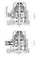
- a tapered braking device for electric winches includes a gear box 4 fixed on an electric winch, a braking cover 13 fixedly connected with the gear box 4, and a section of hollow gear shaft 2 which extends into the center of the gear box 4 and is supported by a bearing 3.
- the hollow gear shaft 2 has a multikey structure.
- a section of core shaft 1 extending from a motor shaft passes through the hollow gear shaft 2, and one extended end portion of the core shaft 1 which extends out of the hollow gear shaft 2 is a hexahedron 18.
- a wedge shape support 5 an elastic element 7, a wedge shape piece B 8 and a wedge shape piece A 9 respectively suit on the section of gear shaft 2 from left to right.
- Outer surfaces of the wedge shape support 5 and the wedge shape piece B 8 have opposite tapered faces.
- Six pieces of braking plates 6 are disposed in the gear box 4 and each has a double tapered face structure. Double tapered friction faces are formed between the wedge shape support 5 and the wedge shape piece B 8 and the six braking plates 6 along the circumferences of the wedge shape support 5 and the wedge shape piece B 8 and the six braking plates 6. Based on the double tapered friction faces, the wedge shape support 5 and the wedge shape piece B 8 and the six braking plates 6 contact with each other or are detached from each other with friction.
- the elastic element 7 is a pagoda-shaped left-hand spring and disposed between the wedge shape support 5 and the wedge shape piece B 8, one end fastened in a hole of the section of gear shaft 2 and the other end fastened in a hole of a ring groove 17 of the wedge shape piece B.
- the wedge shape support 5 and the wedge shape piece B 8 are made of wear resistant alloy steel.
- the elastic element 7 is convenient for pushing the wedge shape piece B when there is no need of braking, so that a gap can be formed between the tapered faces of the wedge shape support and the wedge shape piece B and the double tapered faces of the braking plates (as shown in Figs. 2-5 ).
- the elastic element 7 is compressed to produce a reverse thrust force for pushing the braking plates located on the tapered friction face of the wedge shape piece B far away from the friction faces, so it needs a proper turning force existing between the wedge shape piece B 8 and the elastic element 7, that is, when the two ends of the elastic element 7 are respectively fastened in the holes, the wedge shape piece B 8 needs to has a proper reverse turning force relative to the elastic element 7.
- the section of gear shaft 2 passes through a shaft hole of the wedge shape piece B 8 with gap therebetween, and there is no direct transmission relation between the wedge shape piece B 8 and the section of gear shaft 2.
- An inner hole of the wedge shape piece A 9 is a splined gear hole which can engage with splined teeth of the section of gear shaft 2 thereby forming a direct transmission relation therebetween, and at the same time, the wedge shape piece A 9 is axially limited by a group of C-shaped C-rings in order to prevent the wedge shape piece A from moving.
- Combination end faces of the wedge shape piece B and the wedge shape piece A are cam faces 16 formed by double-inclined-faces.
- a braking clutch base 11 has a center shaft hole which is a hexahedral hole.
- the braking clutch base 11 suits on the hexahedron 18 of the end portion of the section of core shaft 1 and has a direct driving relation with the section of core shaft 1.
- the bearing 12 supports between the braking clutch base 11 and the braking cover 13.
- the braking clutch base 11 has an inner double flange structure 19 arranged along the circumference thereof (as shown in Fig. 3 , Fig. 5 , Fig. 7, Fig. 8 ), matching to the outer double flange structures of the wedge shape piece A and the wedge shape piece B.
- the braking clutch base 11 rotates along with the section of core shaft 1 (clockwise or anticlockwise), and the inner double flanges 19 in the braking clutch base 11 push the outer double flanges 15 of the wedge shape piece A 9 so that the wedge shape piece A rotates along with the braking clutch base 11, thereby the section of gear shaft can be driven to rotate synchronously by the wedge shape piece A.
- the braking clutch base 11 immediately pushes the inner double flanges 19 to the outer double flanges 14 of the wedge shape piece B to drive the wedge shape piece B to rotate.
- the wedge shape piece A drives the section of gear shaft to rotate synchronously, so the section of gear shaft comes back to engage with the above-mentioned deceleration gear group (not shown), thereby driving a tight wire rope reel to rotate to reel up a tight wire rope. Accordingly, the heavy load is lifted.
- the wedge shape piece B is also driven so that the angle difference between the wedge shape piece A and the wedge shape piece B disappears, the gentler cam inclined face of the wedge shape piece B is close to that of the wedge shape piece A (as shown in Figs.
- the braking effect produced in the process of lifting the heavy load to a higher position is described above.
- the braking effect which is described above and produced when the power is off, as shown in Fig. 7 and Fig. 8 , is firstly produced. Then users can operate the motor so that the motor rotates anticlockwise, so the motor core shaft and the braking clutch base all rotate anticlockwise. Instantly, the inner double flanges in the braking clutch base push the outer double flanges of the wedge shape piece B and then the outer double flanges of the wedge shape piece A (as shown in Figs.
- the present invention has the braking effect after assembly. Once the motor works (clockwise or anticlockwise), the braking effect disappears; and when the power is off or cut suddenly, the braking affect is instantly produced, and the heavier the heavy load is, the greater the braking force is, thereby ensuring safe and convenient use.
Landscapes
- Engineering & Computer Science (AREA)
- Mechanical Engineering (AREA)
- Braking Arrangements (AREA)
Applications Claiming Priority (2)
| Application Number | Priority Date | Filing Date | Title |
|---|---|---|---|
| CNB2006100529839A CN100515914C (zh) | 2006-08-17 | 2006-08-17 | 电动绞车锥面刹车装置 |
| PCT/CN2007/002421 WO2008022543A1 (fr) | 2006-08-17 | 2007-08-13 | Dispositif de freinage présentant des surfaces de friction tronconiques, destiné à un treuil électrique |
Publications (3)
| Publication Number | Publication Date |
|---|---|
| EP2053009A1 true EP2053009A1 (fr) | 2009-04-29 |
| EP2053009A4 EP2053009A4 (fr) | 2012-12-05 |
| EP2053009B1 EP2053009B1 (fr) | 2014-01-15 |
Family
ID=37699101
Family Applications (1)
| Application Number | Title | Priority Date | Filing Date |
|---|---|---|---|
| EP07785323.2A Not-in-force EP2053009B1 (fr) | 2006-08-17 | 2007-08-13 | Dispositif de freinage présentant des surfaces de friction tronconiques, destiné à un treuil électrique |
Country Status (5)
| Country | Link |
|---|---|
| US (1) | US7857289B2 (fr) |
| EP (1) | EP2053009B1 (fr) |
| CN (1) | CN100515914C (fr) |
| RU (1) | RU2009105915A (fr) |
| WO (1) | WO2008022543A1 (fr) |
Families Citing this family (15)
| Publication number | Priority date | Publication date | Assignee | Title |
|---|---|---|---|---|
| CN1907837B (zh) | 2006-08-17 | 2012-03-14 | 宁波捷王机电有限公司 | 电动绞车离合装置 |
| CN100515914C (zh) * | 2006-08-17 | 2009-07-22 | 谢玉枝 | 电动绞车锥面刹车装置 |
| CN101823673B (zh) * | 2009-03-06 | 2012-08-08 | 浙江润华机电有限公司 | 一种螺纹静摩擦块式绞盘刹车装置 |
| US8534431B2 (en) | 2010-07-21 | 2013-09-17 | Warn Industries, Inc. | Face tooth hydraulic piston brake |
| CN102075031B (zh) * | 2010-09-15 | 2012-09-19 | 许晓华 | 一种改进的刹车结构 |
| CN102491214B (zh) * | 2011-11-11 | 2013-10-30 | 江苏科技大学 | 一种具有楔块增力结构的摩擦制动装置 |
| CN102730591A (zh) * | 2012-04-18 | 2012-10-17 | 浙江诺和机电有限公司 | 一种绞盘刹车装置 |
| CN103613039B (zh) * | 2013-11-08 | 2015-12-30 | 宁波中皇机电有限公司 | 一种刹车装置 |
| CN105156519B (zh) * | 2015-09-02 | 2018-02-06 | 江苏师范大学 | 一种电磁控制绞盘刹车装置及方法 |
| CN105217507B (zh) * | 2015-09-25 | 2017-06-23 | 江苏科技大学 | 一种内嵌式双楔盘手动摩擦制动装置 |
| CN108069357A (zh) * | 2016-11-14 | 2018-05-25 | 郑州飞机装备有限责任公司 | 一种自动制动机构 |
| CN107816498A (zh) * | 2017-11-17 | 2018-03-20 | 金华职业技术学院 | 一种新型汽车线控制动器 |
| CN112919355B (zh) * | 2019-12-05 | 2023-01-03 | 浙江阜康机械有限公司 | 一种刹车机构 |
| US11661983B2 (en) * | 2020-06-11 | 2023-05-30 | Kuei-Hsin Huang | Brake adjusting device of cable reel |
| CN114278680B (zh) * | 2022-01-04 | 2022-09-20 | 徐州百事利电动车业有限公司 | 一种隐藏式制动系统 |
Family Cites Families (12)
| Publication number | Priority date | Publication date | Assignee | Title |
|---|---|---|---|---|
| DE2121017A1 (de) * | 1971-04-29 | 1972-11-02 | Uher Patent AG. Zug (Schweiz) | Ankerwinde mit Hand- und/oder Motorantrieb |
| US4461460A (en) * | 1982-08-10 | 1984-07-24 | Warn Industries, Inc. | Winch |
| US4625946A (en) * | 1984-03-19 | 1986-12-02 | Ederer Incorporated | Hoist having worm safety device |
| US4545567A (en) * | 1984-04-19 | 1985-10-08 | Warn Industries, Inc. | Winch power transmission |
| US5261646A (en) * | 1991-09-19 | 1993-11-16 | Warn Industries, Inc. | Winch having automatic brake |
| EP0952225A3 (fr) | 1998-02-13 | 2000-08-02 | Nippon Shokubai Co., Ltd. | Procédé pour la préparation de l'acide aspartique avec d'acide fumarique et d'aspartase |
| GB2345482B (en) * | 1999-01-11 | 2001-01-10 | Mbm Technology Ltd | Snatch disconnection lanyard |
| CN2484297Y (zh) * | 2001-06-25 | 2002-04-03 | 川方企业股份有限公司 | 动力绞车的刹车装置 |
| US6520486B2 (en) * | 2001-06-29 | 2003-02-18 | Shih Jyi Huang | Braking device for motive winch |
| US20050242333A1 (en) * | 2004-05-03 | 2005-11-03 | Scott Peterson | Automatic brake mechanism |
| CN2918371Y (zh) * | 2006-06-20 | 2007-07-04 | 川方企业股份有限公司 | 动力绞车之刹车装置 |
| CN100515914C (zh) * | 2006-08-17 | 2009-07-22 | 谢玉枝 | 电动绞车锥面刹车装置 |
-
2006
- 2006-08-17 CN CNB2006100529839A patent/CN100515914C/zh not_active Expired - Fee Related
-
2007
- 2007-08-13 RU RU2009105915/11A patent/RU2009105915A/ru not_active Application Discontinuation
- 2007-08-13 WO PCT/CN2007/002421 patent/WO2008022543A1/fr not_active Ceased
- 2007-08-13 EP EP07785323.2A patent/EP2053009B1/fr not_active Not-in-force
- 2007-08-13 US US12/376,876 patent/US7857289B2/en active Active
Also Published As
| Publication number | Publication date |
|---|---|
| US7857289B2 (en) | 2010-12-28 |
| EP2053009B1 (fr) | 2014-01-15 |
| US20100163815A1 (en) | 2010-07-01 |
| CN1907838A (zh) | 2007-02-07 |
| RU2009105915A (ru) | 2010-09-27 |
| WO2008022543A1 (fr) | 2008-02-28 |
| EP2053009A4 (fr) | 2012-12-05 |
| CN100515914C (zh) | 2009-07-22 |
Similar Documents
| Publication | Publication Date | Title |
|---|---|---|
| EP2053009B1 (fr) | Dispositif de freinage présentant des surfaces de friction tronconiques, destiné à un treuil électrique | |
| EP2058268B1 (fr) | Dispositif de freinage présentant des surfaces de friction planes, destiné à un treuil électrique, et treuil électrique correspondant | |
| US20090218182A1 (en) | Segment brake | |
| US8662140B2 (en) | Composite pull-chain disc mechanism with brake function and electric door operator incorporated with this mechanism | |
| JPH0525800B2 (fr) | ||
| EP3360834B1 (fr) | Ensemble d'anneaux pour régulateur d'ascenseur, régulateur et système d'ascenseur | |
| JP2015053839A (ja) | ブレーキモータ | |
| JPH04159999A (ja) | レバー式捲上機 | |
| EP1248011A2 (fr) | Frein à disque desserré par couple | |
| KR102199659B1 (ko) | 전자브레이크가 없는 무대장치용 리프트 구동장치 | |
| CN112573319B (zh) | 一种绳轮机构及采用该绳轮机构的限速器 | |
| CN201538630U (zh) | 电梯驱动装置 | |
| CN210034214U (zh) | 一种离合式卷筒及绞车 | |
| KR20010102058A (ko) | 리프팅 잭 | |
| JP7640714B2 (ja) | 巻上機 | |
| CN211733507U (zh) | 一种绳轮机构及采用该绳轮机构的限速器 | |
| CA1286654C (fr) | Appareil de levage a cable | |
| CN214114743U (zh) | 一种绳索控制装置 | |
| CN202030411U (zh) | 渐进式防坠安全器 | |
| CN200981800Y (zh) | 电动绞车锥面刹车装置 | |
| CN100485209C (zh) | 轴用装置 | |
| CN2581394Y (zh) | 楔形限速安全钳 | |
| CN2581393Y (zh) | 绳形限速安全钳 | |
| CN200964332Y (zh) | 动力绞车双刹车装置 | |
| CN201647775U (zh) | 电梯曳引机 |
Legal Events
| Date | Code | Title | Description |
|---|---|---|---|
| PUAI | Public reference made under article 153(3) epc to a published international application that has entered the european phase |
Free format text: ORIGINAL CODE: 0009012 |
|
| 17P | Request for examination filed |
Effective date: 20081117 |
|
| AK | Designated contracting states |
Kind code of ref document: A1 Designated state(s): AT BE BG CH CY CZ DE DK EE ES FI FR GB GR HU IE IS IT LI LT LU LV MC MT NL PL PT RO SE SI SK TR |
|
| AX | Request for extension of the european patent |
Extension state: AL BA HR MK RS |
|
| DAX | Request for extension of the european patent (deleted) | ||
| A4 | Supplementary search report drawn up and despatched |
Effective date: 20121105 |
|
| RIC1 | Information provided on ipc code assigned before grant |
Ipc: B66D 1/22 20060101AFI20121029BHEP Ipc: B66D 5/12 20060101ALI20121029BHEP |
|
| REG | Reference to a national code |
Ref country code: DE Ref legal event code: R079 Ref document number: 602007034816 Country of ref document: DE Free format text: PREVIOUS MAIN CLASS: B66D0005020000 Ipc: B66D0001220000 |
|
| RIC1 | Information provided on ipc code assigned before grant |
Ipc: B66D 1/22 20060101AFI20130709BHEP Ipc: B66D 5/12 20060101ALI20130709BHEP |
|
| GRAP | Despatch of communication of intention to grant a patent |
Free format text: ORIGINAL CODE: EPIDOSNIGR1 |
|
| INTG | Intention to grant announced |
Effective date: 20130828 |
|
| GRAS | Grant fee paid |
Free format text: ORIGINAL CODE: EPIDOSNIGR3 |
|
| GRAA | (expected) grant |
Free format text: ORIGINAL CODE: 0009210 |
|
| AK | Designated contracting states |
Kind code of ref document: B1 Designated state(s): AT BE BG CH CY CZ DE DK EE ES FI FR GB GR HU IE IS IT LI LT LU LV MC MT NL PL PT RO SE SI SK TR |
|
| REG | Reference to a national code |
Ref country code: GB Ref legal event code: FG4D Ref country code: CH Ref legal event code: EP |
|
| REG | Reference to a national code |
Ref country code: AT Ref legal event code: REF Ref document number: 649745 Country of ref document: AT Kind code of ref document: T Effective date: 20140215 |
|
| REG | Reference to a national code |
Ref country code: IE Ref legal event code: FG4D |
|
| REG | Reference to a national code |
Ref country code: DE Ref legal event code: R096 Ref document number: 602007034816 Country of ref document: DE Effective date: 20140227 |
|
| REG | Reference to a national code |
Ref country code: NL Ref legal event code: VDEP Effective date: 20140115 |
|
| REG | Reference to a national code |
Ref country code: AT Ref legal event code: MK05 Ref document number: 649745 Country of ref document: AT Kind code of ref document: T Effective date: 20140115 |
|
| REG | Reference to a national code |
Ref country code: LT Ref legal event code: MG4D |
|
| PG25 | Lapsed in a contracting state [announced via postgrant information from national office to epo] |
Ref country code: LT Free format text: LAPSE BECAUSE OF FAILURE TO SUBMIT A TRANSLATION OF THE DESCRIPTION OR TO PAY THE FEE WITHIN THE PRESCRIBED TIME-LIMIT Effective date: 20140115 Ref country code: IS Free format text: LAPSE BECAUSE OF FAILURE TO SUBMIT A TRANSLATION OF THE DESCRIPTION OR TO PAY THE FEE WITHIN THE PRESCRIBED TIME-LIMIT Effective date: 20140515 |
|
| PG25 | Lapsed in a contracting state [announced via postgrant information from national office to epo] |
Ref country code: PT Free format text: LAPSE BECAUSE OF FAILURE TO SUBMIT A TRANSLATION OF THE DESCRIPTION OR TO PAY THE FEE WITHIN THE PRESCRIBED TIME-LIMIT Effective date: 20140515 Ref country code: ES Free format text: LAPSE BECAUSE OF FAILURE TO SUBMIT A TRANSLATION OF THE DESCRIPTION OR TO PAY THE FEE WITHIN THE PRESCRIBED TIME-LIMIT Effective date: 20140115 Ref country code: FI Free format text: LAPSE BECAUSE OF FAILURE TO SUBMIT A TRANSLATION OF THE DESCRIPTION OR TO PAY THE FEE WITHIN THE PRESCRIBED TIME-LIMIT Effective date: 20140115 Ref country code: CY Free format text: LAPSE BECAUSE OF FAILURE TO SUBMIT A TRANSLATION OF THE DESCRIPTION OR TO PAY THE FEE WITHIN THE PRESCRIBED TIME-LIMIT Effective date: 20140115 Ref country code: SE Free format text: LAPSE BECAUSE OF FAILURE TO SUBMIT A TRANSLATION OF THE DESCRIPTION OR TO PAY THE FEE WITHIN THE PRESCRIBED TIME-LIMIT Effective date: 20140115 Ref country code: AT Free format text: LAPSE BECAUSE OF FAILURE TO SUBMIT A TRANSLATION OF THE DESCRIPTION OR TO PAY THE FEE WITHIN THE PRESCRIBED TIME-LIMIT Effective date: 20140115 Ref country code: NL Free format text: LAPSE BECAUSE OF FAILURE TO SUBMIT A TRANSLATION OF THE DESCRIPTION OR TO PAY THE FEE WITHIN THE PRESCRIBED TIME-LIMIT Effective date: 20140115 |
|
| PG25 | Lapsed in a contracting state [announced via postgrant information from national office to epo] |
Ref country code: LV Free format text: LAPSE BECAUSE OF FAILURE TO SUBMIT A TRANSLATION OF THE DESCRIPTION OR TO PAY THE FEE WITHIN THE PRESCRIBED TIME-LIMIT Effective date: 20140115 Ref country code: BE Free format text: LAPSE BECAUSE OF FAILURE TO SUBMIT A TRANSLATION OF THE DESCRIPTION OR TO PAY THE FEE WITHIN THE PRESCRIBED TIME-LIMIT Effective date: 20140115 |
|
| REG | Reference to a national code |
Ref country code: DE Ref legal event code: R097 Ref document number: 602007034816 Country of ref document: DE |
|
| PG25 | Lapsed in a contracting state [announced via postgrant information from national office to epo] |
Ref country code: RO Free format text: LAPSE BECAUSE OF FAILURE TO SUBMIT A TRANSLATION OF THE DESCRIPTION OR TO PAY THE FEE WITHIN THE PRESCRIBED TIME-LIMIT Effective date: 20140115 Ref country code: CZ Free format text: LAPSE BECAUSE OF FAILURE TO SUBMIT A TRANSLATION OF THE DESCRIPTION OR TO PAY THE FEE WITHIN THE PRESCRIBED TIME-LIMIT Effective date: 20140115 Ref country code: DK Free format text: LAPSE BECAUSE OF FAILURE TO SUBMIT A TRANSLATION OF THE DESCRIPTION OR TO PAY THE FEE WITHIN THE PRESCRIBED TIME-LIMIT Effective date: 20140115 Ref country code: EE Free format text: LAPSE BECAUSE OF FAILURE TO SUBMIT A TRANSLATION OF THE DESCRIPTION OR TO PAY THE FEE WITHIN THE PRESCRIBED TIME-LIMIT Effective date: 20140115 |
|
| PLBE | No opposition filed within time limit |
Free format text: ORIGINAL CODE: 0009261 |
|
| STAA | Information on the status of an ep patent application or granted ep patent |
Free format text: STATUS: NO OPPOSITION FILED WITHIN TIME LIMIT |
|
| PG25 | Lapsed in a contracting state [announced via postgrant information from national office to epo] |
Ref country code: PL Free format text: LAPSE BECAUSE OF FAILURE TO SUBMIT A TRANSLATION OF THE DESCRIPTION OR TO PAY THE FEE WITHIN THE PRESCRIBED TIME-LIMIT Effective date: 20140115 Ref country code: SK Free format text: LAPSE BECAUSE OF FAILURE TO SUBMIT A TRANSLATION OF THE DESCRIPTION OR TO PAY THE FEE WITHIN THE PRESCRIBED TIME-LIMIT Effective date: 20140115 |
|
| 26N | No opposition filed |
Effective date: 20141016 |
|
| REG | Reference to a national code |
Ref country code: DE Ref legal event code: R097 Ref document number: 602007034816 Country of ref document: DE Effective date: 20141016 |
|
| PG25 | Lapsed in a contracting state [announced via postgrant information from national office to epo] |
Ref country code: MC Free format text: LAPSE BECAUSE OF FAILURE TO SUBMIT A TRANSLATION OF THE DESCRIPTION OR TO PAY THE FEE WITHIN THE PRESCRIBED TIME-LIMIT Effective date: 20140115 Ref country code: LU Free format text: LAPSE BECAUSE OF FAILURE TO SUBMIT A TRANSLATION OF THE DESCRIPTION OR TO PAY THE FEE WITHIN THE PRESCRIBED TIME-LIMIT Effective date: 20140813 |
|
| REG | Reference to a national code |
Ref country code: CH Ref legal event code: PL |
|
| PG25 | Lapsed in a contracting state [announced via postgrant information from national office to epo] |
Ref country code: CH Free format text: LAPSE BECAUSE OF NON-PAYMENT OF DUE FEES Effective date: 20140831 Ref country code: LI Free format text: LAPSE BECAUSE OF NON-PAYMENT OF DUE FEES Effective date: 20140831 |
|
| REG | Reference to a national code |
Ref country code: IE Ref legal event code: MM4A |
|
| PG25 | Lapsed in a contracting state [announced via postgrant information from national office to epo] |
Ref country code: SI Free format text: LAPSE BECAUSE OF FAILURE TO SUBMIT A TRANSLATION OF THE DESCRIPTION OR TO PAY THE FEE WITHIN THE PRESCRIBED TIME-LIMIT Effective date: 20140115 |
|
| PG25 | Lapsed in a contracting state [announced via postgrant information from national office to epo] |
Ref country code: IE Free format text: LAPSE BECAUSE OF NON-PAYMENT OF DUE FEES Effective date: 20140813 |
|
| PG25 | Lapsed in a contracting state [announced via postgrant information from national office to epo] |
Ref country code: BG Free format text: LAPSE BECAUSE OF FAILURE TO SUBMIT A TRANSLATION OF THE DESCRIPTION OR TO PAY THE FEE WITHIN THE PRESCRIBED TIME-LIMIT Effective date: 20140115 |
|
| PG25 | Lapsed in a contracting state [announced via postgrant information from national office to epo] |
Ref country code: IT Free format text: LAPSE BECAUSE OF FAILURE TO SUBMIT A TRANSLATION OF THE DESCRIPTION OR TO PAY THE FEE WITHIN THE PRESCRIBED TIME-LIMIT Effective date: 20140115 Ref country code: MT Free format text: LAPSE BECAUSE OF FAILURE TO SUBMIT A TRANSLATION OF THE DESCRIPTION OR TO PAY THE FEE WITHIN THE PRESCRIBED TIME-LIMIT Effective date: 20140115 Ref country code: GR Free format text: LAPSE BECAUSE OF FAILURE TO SUBMIT A TRANSLATION OF THE DESCRIPTION OR TO PAY THE FEE WITHIN THE PRESCRIBED TIME-LIMIT Effective date: 20140416 |
|
| PG25 | Lapsed in a contracting state [announced via postgrant information from national office to epo] |
Ref country code: TR Free format text: LAPSE BECAUSE OF FAILURE TO SUBMIT A TRANSLATION OF THE DESCRIPTION OR TO PAY THE FEE WITHIN THE PRESCRIBED TIME-LIMIT Effective date: 20140115 Ref country code: HU Free format text: LAPSE BECAUSE OF FAILURE TO SUBMIT A TRANSLATION OF THE DESCRIPTION OR TO PAY THE FEE WITHIN THE PRESCRIBED TIME-LIMIT; INVALID AB INITIO Effective date: 20070813 |
|
| REG | Reference to a national code |
Ref country code: FR Ref legal event code: PLFP Year of fee payment: 10 |
|
| REG | Reference to a national code |
Ref country code: FR Ref legal event code: PLFP Year of fee payment: 11 |
|
| REG | Reference to a national code |
Ref country code: FR Ref legal event code: PLFP Year of fee payment: 12 |
|
| PGFP | Annual fee paid to national office [announced via postgrant information from national office to epo] |
Ref country code: DE Payment date: 20220822 Year of fee payment: 16 |
|
| PGFP | Annual fee paid to national office [announced via postgrant information from national office to epo] |
Ref country code: GB Payment date: 20230731 Year of fee payment: 17 |
|
| PGFP | Annual fee paid to national office [announced via postgrant information from national office to epo] |
Ref country code: FR Payment date: 20230720 Year of fee payment: 17 |
|
| REG | Reference to a national code |
Ref country code: DE Ref legal event code: R119 Ref document number: 602007034816 Country of ref document: DE |
|
| PG25 | Lapsed in a contracting state [announced via postgrant information from national office to epo] |
Ref country code: DE Free format text: LAPSE BECAUSE OF NON-PAYMENT OF DUE FEES Effective date: 20240301 |
|
| GBPC | Gb: european patent ceased through non-payment of renewal fee |
Effective date: 20240813 |
|
| PG25 | Lapsed in a contracting state [announced via postgrant information from national office to epo] |
Ref country code: GB Free format text: LAPSE BECAUSE OF NON-PAYMENT OF DUE FEES Effective date: 20240813 |
|
| PG25 | Lapsed in a contracting state [announced via postgrant information from national office to epo] |
Ref country code: FR Free format text: LAPSE BECAUSE OF NON-PAYMENT OF DUE FEES Effective date: 20240831 |