EP2053182A2 - Coffrage modulaire réutilisable pour la réalisation de dalles de béton armé nervurées - Google Patents
Coffrage modulaire réutilisable pour la réalisation de dalles de béton armé nervurées Download PDFInfo
- Publication number
- EP2053182A2 EP2053182A2 EP08166885A EP08166885A EP2053182A2 EP 2053182 A2 EP2053182 A2 EP 2053182A2 EP 08166885 A EP08166885 A EP 08166885A EP 08166885 A EP08166885 A EP 08166885A EP 2053182 A2 EP2053182 A2 EP 2053182A2
- Authority
- EP
- European Patent Office
- Prior art keywords
- portal
- shaped
- head
- edges
- formwork according
- Prior art date
- Legal status (The legal status is an assumption and is not a legal conclusion. Google has not performed a legal analysis and makes no representation as to the accuracy of the status listed.)
- Withdrawn
Links
Images



Classifications
-
- E—FIXED CONSTRUCTIONS
- E04—BUILDING
- E04G—SCAFFOLDING; FORMS; SHUTTERING; BUILDING IMPLEMENTS OR AIDS, OR THEIR USE; HANDLING BUILDING MATERIALS ON THE SITE; REPAIRING, BREAKING-UP OR OTHER WORK ON EXISTING BUILDINGS
- E04G11/00—Forms, shutterings, or falsework for making walls, floors, ceilings, or roofs
- E04G11/36—Forms, shutterings, or falsework for making walls, floors, ceilings, or roofs for floors, ceilings, or roofs of plane or curved surfaces end formpanels for floor shutterings
- E04G11/40—Forms, shutterings, or falsework for making walls, floors, ceilings, or roofs for floors, ceilings, or roofs of plane or curved surfaces end formpanels for floor shutterings for coffered or ribbed ceilings
- E04G11/46—Forms, shutterings, or falsework for making walls, floors, ceilings, or roofs for floors, ceilings, or roofs of plane or curved surfaces end formpanels for floor shutterings for coffered or ribbed ceilings of hat-like or trough-like shape encasing a rib or the section between two ribs or encasing one rib and its adjacent flat floor or ceiling section
Definitions
- the present invention concerns the equipment for making reinforced concrete floors and in particular it concerns a new type of reusable modular formwork for making ribbed reinforced concrete floors.
- Reusable formworks are known, for example, which are constituted by prefabricated plane panels or elements, in wood, metal or plastic, properly supported by means of temporary bearing structures suited to maintain the formworks in such a position as to form a substantially flat and continuous surface making up the bottom of the formwork, on which concrete is cast.
- Said panels and said temporary bearing structure can be removed only after the complete curing of the floor.
- Reusable plane formworks which are made of a plastic material and comprise a monolithic body with at least one smooth plane surface at the bottom of the formwork, suitable for casting concrete thereon.
- Said known reusable formworks are substantially rectangular in plan view, with modular width and length, in the order of 60-100 cm and comprise perimetral ribs at right angles with said plane surface and shaped so as to be suitable for coupling with the adjacent formworks, to which they are integrally constrained by means of suitable fixing devices, like for example bolts, tie rods or other devices.
- Said fixing devices are such as to successively allow the formworks to be rapidly dismantled.
- Said reusable plastic formworks are particularly appreciated thanks to the fact that they are lighter and easier to handle than wooden panels, compared to which they therefore also require less labour.
- a further advantage is represented by the fact that, once said reusable plastic formworks have been removed, the lower surface of the floor is smooth and well finished, differently from what happens when wooden panels or disposable foam formworks are used.
- the main problem posed by the known reinforcing systems lies in that the formworks used must remain in place until the curing of the floor is complete and therefore cannot be reused during the long time interval between the concrete casting and the completion of the curing process.
- the need is also known to produce ribbed concrete floors, with a flat, approx. 5 cm thick slab and reinforced beams arranged at a distance of approx. 50-60 cm.
- disposable panels or formworks consisting of a block of foamed plastic material, typically polystyrene, having an elongated rectangular shape in plan view and a generically parallelepiped cross section with central or lateral seats to provide the housing where the reinforcing bars are placed before concrete is cast in order to obtain the reinforced ribs of the floor.
- foamed plastic material typically polystyrene
- the subject of the present invention is a new type of reusable modular formwork for making ribbed reinforced concrete floors.
- the main object of the present invention is to ensure the rapid laying of reusable modular elements of the portal-shaped type for making ribbed reinforced concrete floors, wherein said portal-shaped elements rest and are maintained in place on a temporary bearing structure.
- Another important object of the present invention is to allow the rapid removal of said portal-shaped elements, dismantling said temporary bearing structure.
- a further important object of the present invention is to make ribbed floors comprising beams with enlarged heads, using modular head elements of the portal type shaped in a particular way, with no need to use any further specific equipment.
- a further important object of the present invention is to make ribbed floors with partitions, using modular partition elements of the portal type shaped in a particular way.
- Another object of the present invention is to allow said portal-shaped elements to be dismantled and then reused just a few days after the concrete has been cast, in any case keeping the floor propped until the concrete curing process has been completed.
- An important advantage offered by the present invention lies in that it requires fewer portal-shaped elements in the whole, since it is possible to reuse the same portal-shaped elements almost immediately, thanks to the fact that it is not necessary to leave them in place until the concrete curing process has been completed.
- the new type of reusable modular formwork for making ribbed reinforced concrete floors comprising a plurality of modular portal elements, shaped in a particular way, each one comprising in turn a horizontal upper base in contact with the concrete casting and at least two opposing lateral walls in contact with the concrete casting, with lower edges suited to rest on a temporary bearing structure.
- Said portal-shaped elements also comprise head edges especially shaped with ribs and/or seats suited to be coupled and precisely aligned with adjacent modular elements.
- said formwork may also comprise one or more modular portal-shaped elements comprising, in addition to said horizontal upper base and said two opposing lateral walls with said lower edges, also one or more head walls in contact with the concrete casting, with lower edges or lower plane parts in contact with the concrete casting, for making floors with ribbing in two orthogonal directions.
- each one of said portal-shaped modular elements comprises a monolithic element, rectangular in plan view, with modular lenght, for example 60-100 cm, and overall modular width comparable to the distance between the beams (L1) of the ribbed floor, for example 60 cm, excluding the lateral supporting and overlapping parts.
- the portal-shaped modular element (Sn) has in its whole a generically parallelepiped or trapezoidal shape, preferably with portal-shaped cross section, that is, with at least two preferably plane opposing lateral walls (S21, S22), for example slightly inclined, and with preferably plane horizontal upper base (S1).
- Each one of said lateral walls (S21, S22) comprises a lower edge (S31, S32) suited to rest on the temporary bearing structure, wherein said lateral wall (S21)/(S22) and said lower edge (S31)/(S32) of each portal-shaped element (Sn) is suited to form, if necessary in combination with the upper surface of the elements of the bearing structure and/or with a further portal-shaped element (Sn) arranged symmetrically in relation to said element of the structure, a rib suited to house the reinforcing bars and the concrete casting of the beam (L1) of the ribbed floor.
- edges (S411, S421) of said upper base (S1) and/or of said lateral walls (S21, S22) forming the opposing open ends (S41, S42) of each portal-shaped element (Sn) are completely or partially shaped with projections and/or seats suited to be aligned and precisely coupled with other modular elements.
- edges (S411, S421) of one or both the open ends (S41, S42) are folded, completely or partially, for example in the shape of a U facing upwards, wherein the U-shaped male edge (S411) of one end, or male end (S41), has shape and size suitable for insertion in the U-shaped female edge (S421) of the opposite end, or female end (S42), of the portal-shaped modular element (Sn) aligned therewith.
- said U-shaped male edges (S5411) comprise one or more ribs (S412) on the concave part of the edge itself ( Figure 1b ), in such a way as to prevent the U-shaped female (S421) and male (S411) edges from overlapping and being coupled incorrectly.
- positioning side by side two of said new portal-shaped elements (Sn) means that the opposing lateral walls (S21, S22) and the lower edges (S31, S32) of the two adjacent portal-shaped elements (Sn) will define, in combination with one or more elements of the temporary bearing structure, a seat whose width and depth are such as to house the reinforcement for making the ribs or beams (L1) of the ribbed reinforced concrete floor.
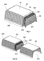
- the invention also provides for the use of portal-shaped elments, hereinafter called head elements (St) ( Figure 2 ), particularly suited to form the enlarged heads of the beams of the ribbed floor, that is, heads whose width exceeds the width of the beam body, suited to ensure greater shearing strength of the beam or rib at the level of the bearing point.
- head elements hereinafter called head elements (St) ( Figure 2 )
- St portal-shaped elments
- Said modular head element (St) is a monolithic body substantially rectangular in plan view, whose size, in plan view, is preferably comparable to the size of said normal portal-shaped elements (Sn), that is, having modular length, for example 60-100 cm, and width comparable to the distance between the beams of the ribbed floor, for example 60 cm, excluding the supporting and overlapping parts.
- Said portal-shaped head elements (St) also comprise a horizontal plane upper base (S1), at least two opposing lateral walls (S21, S22), for example slightly inclined, and at least one closed end (S51), that is, at least one head wall (S511) in contact with the concrete casting, with horizontal plane lower part or edge (S61) in contact with the concrete casting, in order to increase the thickness of the beam, and wherein said lateral walls (S21, S22) converge to form, with said plane upper base (S1), a projection that is substantially triangular, trapezoidal or generically arched in plan view, with longitudinal axis of symmetry in relation to the portal-shaped element (St) itself.
- the base of said projection coincides with one of the coupling ends, male (S41) or female (S42), while said head wall (S511) connecting said lateral walls (S21, S22) is directed towards the front edge (S611) of said lower plane part (S61) and is preferably positioned backward in relation to it.
- portal-shaped head element (St) has the edge (S421) of the open end (S42) folded in the shape of a U in order to be aligned with and removably fixed to a portal-shaped element (Sn) aligned behind it, as shown in Figure 2 .
- one or more portal-shaped element/s is/are used, hereinafter called partition element/s (Sp1, Sp2) ( Figures 3 and 4 ), with upper base (S1) at least partially lowered, that is, comprising at least one partially or completely lowered intermediate part (S131, S132), interposed between two opposing end sections (S11, S12) raised substantially at the same height, that is at the height of said plane upper base (S1) in contact with the concrete casting of the adjacent portal-shaped elements (Sn, Sp1, Sp2, St).
- partition element/s Sp1, Sp2
- Said portal-shaped partition elements comprise, analogously to said portal-shaped elements (Sn), lateral lower edges (S31, S32) suited to rest on said temporary bearing structure and open ends (S41, S42) with edges (S411, S412) provided with seats and/or projections suited to be aligned with and removably fixed to the other portal-shaped elements.
- Said portal-shaped partition elements (Sp1, Sp2), properly alternated with said portal-shaped elements (Sn), create the seats for casting the partitions of the floor, that is, of cross ribs of the slab, in order to distribute the load among the beams or ribs of the floor.
- portal-shaped elements with closed ends comprising an upper base in contact with the concrete casting (S1), at least two opposing lateral walls (S21, S22) in contact with the concrete casting, and at least two head walls (S71, S72), each one provided with a lower edge or plane head part (S61, S62) in contact with the concrete casting.
- Positioning said portal-shaped elements (Sc1, Sc2) beside other portal-shaped elements arranged symmetrically in relation to the elements of the temporary bearing structure means obtaining seats that are defined at the bottom by said lateral lower edges (S31, S32) and at the sides by said lateral walls (S21, S22), wherein the width and depth of said seats are such as to house the reinforcement for making the ribs of the reinforced concrete floor.
- Said head walls (S71, S72), instead, substantially serve as covering or formwork bottom surfaces and, if aligned with other modular elements (Sc1,
- the width of said lower head parts (S61, S62) exceeds the width of said lateral lower edges (S31, S32).
- said portal-shaped element (Sc1) with closed ends may be rectangular in plan view, with ribbed (S8) lateral walls (S21', S22') and head walls (S71', S72').
- said portal-shaped element with closed ends may be square in plan view, with non ribbed upper base (S1), lateral walls (S21, S22) and head walls (S71, S72).
- said portal-shaped element with closed ends can have ribbed lateral walls (S21', S22') and/or head walls (S71', S72').
- head and connection elements (Sb) ( Figure 7 ), which comprise an upper base (S1), at least two opposing lateral walls (S21', S22') and one or two closed head walls (S71', S72'), wherein said head and connection element (Sb) has shape and size suited to allow it to be inserted, at least partially, in longitudinal direction, in at least one of said portal-shaped elements, which can be a normal (Sn) and/or head (St) and/or partition (Sp1, Sp2) element.
- Sn normal
- St head
- Sp1, Sp2 partition
- Said head and connection element (Sb) may also comprise one or more lower feet (S9) suited to rest on the quick-dismantling elements that make up the temporary bearing structure.
- said head and connection element (Sb) can be used as a closing element of an open end (S41 and/or S42) of a modular element (Sn, St, Sp1, Sp2).
- said head and connection element (Sb) is at least partially inserted, longitudinally, in at least one portal-shaped element (Sn), so that the relative upper bases (S1, S1') and lateral walls (S21', S22') are correspondingly coupled.
- Said head and connection element (Sb) can be inserted in the portal-shaped element (Sn) to different degrees, in such a way as to increase/reduce the overall length of the formwork, according to the actual size of the ribbing to be obtained.
- Said head and connection element (Sb) can thus be effectively used to connect or join two aligned portal-shaped modular elements (Sn, St, Sp1, Sp2) ( Figure 8a ).
- said head and connection element (Sb) is partially inserted in both the aligned modular elements (Sn, St, Sp1, Sp2), so that only an intermediate portion of its upper base (S1') and of its lateral walls (S21', S22') is external.
- each portal-shaped element comprises, distributed on the outer and/or inner surface of the upper base (S1') and/or of the lateral walls (S21', S22') and/or of the head walls (S71', S72'), a succession of ribs (S8), preferably transversal to the longitudinal direction of the elements themselves.
- said head and connection element (Sb) can be provided with a plurality of regularly spaced ribs (S8), which define an alternating succession of recesses (S81), wherein said recesses (S81) have shape and size suitable for the insertion of said U-shaped edges (S411, S421) of the portal-shaped elements (Sn, St, Sp1, Sp2).
- some of said recesses (S81) have shape and size suitable for the alternate insertion of the U-shaped male (S411) or female (S421) edge.
- said portal-shaped elements must be positioned on said temporary bearing structure in such a way as to create a plurality of continuous parallel seats, each one defined laterally between said lateral walls (S21, S22) of said portal-shaped elements and at the bottom by said edges (S31, S32) and/or plane base parts (S61, S62).
- Said seats alternate with plane surfaces, in turn defined by said upper bases (S1), on which the concrete casting of the floor slab (L2) will be carried out.
- a further important advantage offered by the present invention lies in that, after the formwork has been dismantled, the floor carried out in this way has a perfectly smooth lower surface, while this does not happen with disposable formworks which remain exposed and are subjected to weather agents that damage them and cause them to crumble, thus negatively affecting the appearance of the finished product.
- portal-shaped elements (Sn, St, Sp1, Sp2, Sc1, Sc2, Sb) preferably have bevelled and/or rounded corners.
Landscapes
- Engineering & Computer Science (AREA)
- Architecture (AREA)
- Mechanical Engineering (AREA)
- Civil Engineering (AREA)
- Structural Engineering (AREA)
- Forms Removed On Construction Sites Or Auxiliary Members Thereof (AREA)
Applications Claiming Priority (1)
| Application Number | Priority Date | Filing Date | Title |
|---|---|---|---|
| ITPD20070347 ITPD20070347A1 (it) | 2007-10-22 | 2007-10-22 | Casseratura modulare riutilizzabile per la realizzazione di solai nervati in c. a. |
Publications (2)
| Publication Number | Publication Date |
|---|---|
| EP2053182A2 true EP2053182A2 (fr) | 2009-04-29 |
| EP2053182A3 EP2053182A3 (fr) | 2013-01-30 |
Family
ID=40032433
Family Applications (2)
| Application Number | Title | Priority Date | Filing Date |
|---|---|---|---|
| EP08166430.2A Active EP2053181B1 (fr) | 2007-10-22 | 2008-10-13 | Coffrage modulaire pour la réalisation de dalles de béton armé à nervures croisées |
| EP08166885A Withdrawn EP2053182A3 (fr) | 2007-10-22 | 2008-10-17 | Coffrage modulaire réutilisable pour la réalisation de dalles de béton armé nervurées |
Family Applications Before (1)
| Application Number | Title | Priority Date | Filing Date |
|---|---|---|---|
| EP08166430.2A Active EP2053181B1 (fr) | 2007-10-22 | 2008-10-13 | Coffrage modulaire pour la réalisation de dalles de béton armé à nervures croisées |
Country Status (2)
| Country | Link |
|---|---|
| EP (2) | EP2053181B1 (fr) |
| IT (1) | ITPD20070347A1 (fr) |
Cited By (1)
| Publication number | Priority date | Publication date | Assignee | Title |
|---|---|---|---|---|
| WO2023089600A1 (fr) * | 2022-12-12 | 2023-05-25 | Movasat Nader | Coffrage plastique réutilisable utilisé en remplacement des blocs dans des dalles unidirectionnelles de type blocs et solives avec des solives préfabriquées (acier ou béton renforcé) |
Families Citing this family (1)
| Publication number | Priority date | Publication date | Assignee | Title |
|---|---|---|---|---|
| ES2530595A1 (es) * | 2014-06-10 | 2015-03-03 | Sustainable Building S L | Sistema para construcción de forjados reticulares con diferente geometría de retículas |
Family Cites Families (12)
| Publication number | Priority date | Publication date | Assignee | Title |
|---|---|---|---|---|
| GB191206201A (en) * | 1912-03-12 | 1912-10-03 | Trussed Concrete Steel Co | Improvements in and relating to Ferro Concrete Construction for Floors and the like. |
| US1494538A (en) * | 1923-01-05 | 1924-05-20 | Gent Oscar Lawrence | Concrete mold |
| US1633715A (en) * | 1924-04-23 | 1927-06-28 | Nat Concrete Metal Forms Corp | Concrete form for building construction |
| US1530851A (en) * | 1924-07-22 | 1925-03-24 | Leon R Paul | Floor form |
| GB704541A (en) * | 1951-01-09 | 1954-02-24 | Arnold Loose | Shuttering for ceilings |
| DE1286730B (de) * | 1963-12-11 | 1969-01-09 | Hanekamp Hermann | Kunststoff-Fuellkoerper zur Herstellung von Beton-Kassetten-, Rippendecken od. dgl. |
| US3807681A (en) * | 1971-12-30 | 1974-04-30 | Kane S | Forming system for concrete floor and roof decks |
| GB2005332B (en) * | 1977-09-21 | 1982-03-24 | Rapid Metal Developments Ltd | Formword support system |
| GB2100331B (en) * | 1981-06-08 | 1985-08-07 | Acrow Eng Ltd | Formwork system |
| FR2858343B1 (fr) * | 2003-07-31 | 2007-04-20 | Fimurex | Entrevous emboitable moule |
| MX2007007608A (es) * | 2004-12-23 | 2007-08-03 | Bernard Mcnamara | Pared de encofrado modular con conectores de junta de cola de milano. |
| ATE541099T1 (de) * | 2005-06-23 | 2012-01-15 | Plasticform S R L | Füll- und dämmelement und bausystem mit solch einem element |
-
2007
- 2007-10-22 IT ITPD20070347 patent/ITPD20070347A1/it unknown
-
2008
- 2008-10-13 EP EP08166430.2A patent/EP2053181B1/fr active Active
- 2008-10-17 EP EP08166885A patent/EP2053182A3/fr not_active Withdrawn
Cited By (1)
| Publication number | Priority date | Publication date | Assignee | Title |
|---|---|---|---|---|
| WO2023089600A1 (fr) * | 2022-12-12 | 2023-05-25 | Movasat Nader | Coffrage plastique réutilisable utilisé en remplacement des blocs dans des dalles unidirectionnelles de type blocs et solives avec des solives préfabriquées (acier ou béton renforcé) |
Also Published As
| Publication number | Publication date |
|---|---|
| EP2053182A3 (fr) | 2013-01-30 |
| ITPD20070347A1 (it) | 2009-04-23 |
| EP2053181A3 (fr) | 2013-02-27 |
| EP2053181A2 (fr) | 2009-04-29 |
| EP2053181B1 (fr) | 2016-06-01 |
Similar Documents
| Publication | Publication Date | Title |
|---|---|---|
| US3238684A (en) | Reinforcement and shuttering assembly for concrete | |
| AU2015100173B4 (en) | An interlocking masonry block | |
| US8181415B2 (en) | Modular construction block | |
| US20090188186A1 (en) | Building Construction System and Structural Modules Thereof | |
| US7837174B2 (en) | Modular formwork wall with dovetail joint connectors | |
| DK2630306T3 (en) | Assemblable disposable FOR CONSTRUCTION OF MODULAR formwork FOR PRODUCTION OF CONCRETE FOUNDATION | |
| US8074958B1 (en) | Lintel form for concrete and block constructions | |
| US10260233B2 (en) | Prefabricated module for casting a concrete wall | |
| KR20200104108A (ko) | 자립형 거푸집을 이용한 합벽 순타 시공용 무지주 거푸집 시스템 및 이의 시공 방법 | |
| WO2000065166A1 (fr) | Structure a cadre metallique et procede de construction utilisant celle-ci | |
| KR100949785B1 (ko) | 피씨 보 제작용 몰드 | |
| KR101345898B1 (ko) | 선 조립된 철근다발을 가지는 벽체 및 이를 이용한 벽체 시공 방법 | |
| US3279135A (en) | Composite column for precast concrete structures | |
| KR101588115B1 (ko) | 트러스 데크를 활용한 프리패브 중공벽 및 그 제작방법 | |
| MX2012002674A (es) | Techo a base de bloques aligerados y su metodo de construccion. | |
| CN210164241U (zh) | 一种预设模板的预制边梁 | |
| EP2053181B1 (fr) | Coffrage modulaire pour la réalisation de dalles de béton armé à nervures croisées | |
| GB2056538A (en) | Shuttering system | |
| KR102848181B1 (ko) | 모듈러 콘크리트 건축물 및 그 시공 방법 | |
| AU5785001A (en) | A formwork component | |
| AU2014101506A4 (en) | An interlocking corner masonry block | |
| KR20100138454A (ko) | 조립식 유로폼 및 이것을 이용한 건축물의 시공방법 | |
| JP2864905B2 (ja) | プレキャスト壁の接合方法 | |
| JPH0144685Y2 (fr) | ||
| KR101554208B1 (ko) | 콘크리트 타설용 거푸집 지지체 |
Legal Events
| Date | Code | Title | Description |
|---|---|---|---|
| PUAI | Public reference made under article 153(3) epc to a published international application that has entered the european phase |
Free format text: ORIGINAL CODE: 0009012 |
|
| AK | Designated contracting states |
Kind code of ref document: A2 Designated state(s): AT BE BG CH CY CZ DE DK EE ES FI FR GB GR HR HU IE IS IT LI LT LU LV MC MT NL NO PL PT RO SE SI SK TR |
|
| AX | Request for extension of the european patent |
Extension state: AL BA MK RS |
|
| PUAL | Search report despatched |
Free format text: ORIGINAL CODE: 0009013 |
|
| AK | Designated contracting states |
Kind code of ref document: A3 Designated state(s): AT BE BG CH CY CZ DE DK EE ES FI FR GB GR HR HU IE IS IT LI LT LU LV MC MT NL NO PL PT RO SE SI SK TR |
|
| AX | Request for extension of the european patent |
Extension state: AL BA MK RS |
|
| RIC1 | Information provided on ipc code assigned before grant |
Ipc: E04G 11/46 20060101AFI20121221BHEP Ipc: E04B 5/26 20060101ALI20121221BHEP |
|
| AKY | No designation fees paid | ||
| REG | Reference to a national code |
Ref country code: DE Ref legal event code: R108 Effective date: 20131002 |
|
| STAA | Information on the status of an ep patent application or granted ep patent |
Free format text: STATUS: THE APPLICATION IS DEEMED TO BE WITHDRAWN |
|
| 18D | Application deemed to be withdrawn |
Effective date: 20130731 |