EP2053202A2 - Außendichtung für eine Turbinenschaufel mit verbesserter thermomechanischen Ermüdungsbeständigkeit - Google Patents
Außendichtung für eine Turbinenschaufel mit verbesserter thermomechanischen Ermüdungsbeständigkeit Download PDFInfo
- Publication number
- EP2053202A2 EP2053202A2 EP08253487A EP08253487A EP2053202A2 EP 2053202 A2 EP2053202 A2 EP 2053202A2 EP 08253487 A EP08253487 A EP 08253487A EP 08253487 A EP08253487 A EP 08253487A EP 2053202 A2 EP2053202 A2 EP 2053202A2
- Authority
- EP
- European Patent Office
- Prior art keywords
- outer air
- thickness
- air seal
- blade outer
- blade
- Prior art date
- Legal status (The legal status is an assumption and is not a legal conclusion. Google has not performed a legal analysis and makes no representation as to the accuracy of the status listed.)
- Granted
Links
Images

Classifications
-
- F—MECHANICAL ENGINEERING; LIGHTING; HEATING; WEAPONS; BLASTING
- F01—MACHINES OR ENGINES IN GENERAL; ENGINE PLANTS IN GENERAL; STEAM ENGINES
- F01D—NON-POSITIVE DISPLACEMENT MACHINES OR ENGINES, e.g. STEAM TURBINES
- F01D11/00—Preventing or minimising internal leakage of working-fluid, e.g. between stages
- F01D11/08—Preventing or minimising internal leakage of working-fluid, e.g. between stages for sealing space between rotor blade tips and stator
- F01D11/12—Preventing or minimising internal leakage of working-fluid, e.g. between stages for sealing space between rotor blade tips and stator using a rubstrip, e.g. erodible. deformable or resiliently-biased part
- F01D11/122—Preventing or minimising internal leakage of working-fluid, e.g. between stages for sealing space between rotor blade tips and stator using a rubstrip, e.g. erodible. deformable or resiliently-biased part with erodable or abradable material
-
- F—MECHANICAL ENGINEERING; LIGHTING; HEATING; WEAPONS; BLASTING
- F05—INDEXING SCHEMES RELATING TO ENGINES OR PUMPS IN VARIOUS SUBCLASSES OF CLASSES F01-F04
- F05D—INDEXING SCHEME FOR ASPECTS RELATING TO NON-POSITIVE-DISPLACEMENT MACHINES OR ENGINES, GAS-TURBINES OR JET-PROPULSION PLANTS
- F05D2230/00—Manufacture
- F05D2230/90—Coating; Surface treatment
-
- F—MECHANICAL ENGINEERING; LIGHTING; HEATING; WEAPONS; BLASTING
- F05—INDEXING SCHEMES RELATING TO ENGINES OR PUMPS IN VARIOUS SUBCLASSES OF CLASSES F01-F04
- F05D—INDEXING SCHEME FOR ASPECTS RELATING TO NON-POSITIVE-DISPLACEMENT MACHINES OR ENGINES, GAS-TURBINES OR JET-PROPULSION PLANTS
- F05D2250/00—Geometry
- F05D2250/10—Two-dimensional
- F05D2250/18—Two-dimensional patterned
- F05D2250/182—Two-dimensional patterned crenellated, notched
-
- F—MECHANICAL ENGINEERING; LIGHTING; HEATING; WEAPONS; BLASTING
- F05—INDEXING SCHEMES RELATING TO ENGINES OR PUMPS IN VARIOUS SUBCLASSES OF CLASSES F01-F04
- F05D—INDEXING SCHEME FOR ASPECTS RELATING TO NON-POSITIVE-DISPLACEMENT MACHINES OR ENGINES, GAS-TURBINES OR JET-PROPULSION PLANTS
- F05D2250/00—Geometry
- F05D2250/70—Shape
-
- F—MECHANICAL ENGINEERING; LIGHTING; HEATING; WEAPONS; BLASTING
- F05—INDEXING SCHEMES RELATING TO ENGINES OR PUMPS IN VARIOUS SUBCLASSES OF CLASSES F01-F04
- F05D—INDEXING SCHEME FOR ASPECTS RELATING TO NON-POSITIVE-DISPLACEMENT MACHINES OR ENGINES, GAS-TURBINES OR JET-PROPULSION PLANTS
- F05D2300/00—Materials; Properties thereof
- F05D2300/60—Properties or characteristics given to material by treatment or manufacturing
- F05D2300/611—Coating
-
- Y—GENERAL TAGGING OF NEW TECHNOLOGICAL DEVELOPMENTS; GENERAL TAGGING OF CROSS-SECTIONAL TECHNOLOGIES SPANNING OVER SEVERAL SECTIONS OF THE IPC; TECHNICAL SUBJECTS COVERED BY FORMER USPC CROSS-REFERENCE ART COLLECTIONS [XRACs] AND DIGESTS
- Y02—TECHNOLOGIES OR APPLICATIONS FOR MITIGATION OR ADAPTATION AGAINST CLIMATE CHANGE
- Y02T—CLIMATE CHANGE MITIGATION TECHNOLOGIES RELATED TO TRANSPORTATION
- Y02T50/00—Aeronautics or air transport
- Y02T50/60—Efficient propulsion technologies, e.g. for aircraft
Definitions
- the invention relates to an abradable protective coating for blade outer air seals, and more particularly to an abradable coating that is geometrically conditioned to result in more uniform thermal heat flux regions throughout the blade outer air seal.
- Blade outer air seals in the high pressure, high temperature regions within a gas turbine engine generally include some form of protective layering, such as a thermal barrier coating (TBC). These protective layers function to protect the blade outer air seals from oxidation, corrosion, and thermal-mechanical fatigue that can reduce part life and the repair-ability of engine run parts.
- TBC thermal barrier coating
- the seals include an abradable ceramic TBC that is removed over the life of the part by the rotation of turbine blades adjacent it.
- the effect of turbine blade abrasion is to create a clearance pocket on the blade outer air seal radially adjacent the turbine blade tips.
- Abrasion of the TBC typically provides a minimum clearance between the outer air seals and the turbine blades such that gas flow around the tips of the turbines is reduced. This reduction in gas flow prevents leakage that would result in reduction of engine efficiency.
- the pocket assists in reducing gas flow around the blade tips, some of the ancillary effects of this pocket are generally not desirable.
- the pocket is generally more pronounced along a turbine blade rub path that is created by rotating motion of the turbine blades relative to the static blade outer air seal.
- the pocket is also a region of high heat flux due to aerodynamics and less insulating material being located in that region.
- One drawback of the conventional pocket blade outer air seal design is that it geometrically creates a non-uniform TBC thickness. The overall effect of this nonuniformity in the TBC creates a thermal gradient that increases thermal-mechanical fatigue, and concentrates stresses in the blade outer air seals. This phenomenon accelerates base metal degradation in the pocket area.
- a blade outer air seal for a gas turbine includes an abradable coating that is shaped to reduce or eliminate creation of a pocket of reduced layer thickness.
- the abradable coating has thickness within a blade rub path area that is greater than its thickness in areas outside the blade rub path. A portion of the greater thickness coating in the blade path area is removable by service use of the gas turbine, so that a generally uniform thickness of the abradable coating results.
- a method of providing a blade outer air seal includes the steps of providing a blade outer air seal with an abradable coating that has areas of different thickness, disposing the blade outer air seal within a gas turbine; and causing turbine blades to rotate and remove a portion of the abradable coating in a blade rub path so that the abradable coating has a generally uniform thickness during regular service use of the gas turbine.
- FIG. 1 shows portions of high pressure turbine section 10 of a gas turbine engine.
- Turbine section 10 includes turbine blades 12 that extend radially outward from rotor disk 17.
- Blade outer air seals 20 are arranged circumferentially around the outer ends of blades 12 and act as an outer wall for gas flow G in the turbine section 10.
- Blade outer air seal 20 is secured by a support section 18 to outer case 16, which creates a boundary for gas flow G and extends around turbine section 10.
- Blade outer air seals 20 include an abradable coating 22 on their inner surface which faces and interacts with the tips T of blades 12.
- the abradable coating typically includes a bond coat on the substrate of blade outer air seal 20, and a thermal barrier coating (TBC) over the bond coat.
- TBC thermal barrier coating
- the substrate of blade outer air seal 20 is typically a nickel or cobalt based superalloy.
- the bond coat may be, for example a MCrAlY alloy or an aluminide layer (such as nickel aluminide, nickel chromium aluminide, and platinum aluminide).
- MCrAlY refers to a metal coating composition in which M denotes nickel, cobalt, iron, or mixtures thereof; Cr denotes chromium; Al denotes aluminum; and Y denotes yttrium.
- the bond layer can be deposited onto the substrate utilizing processes such as a thermal spray, vapor deposition, arc deposition, sputtering, or electron beam physical vapor deposition.
- the thickness of the bond coat generally ranges from between about 0.13 mm to 0.3 mm (about 5 to 12 mils).
- the abradable TBC may be, for example, of a ceramic such as yttria stabilized zirconia, although other TBCs can be used.
- a ceramic such as yttria stabilized zirconia
- One example of a commonly used TBC is 7 or 8 weight percent yttria stabilized zirconia.
- the thickness of the TBC generally ranges from between about 0.25 mm to about 1.02 mm (10 to 40 mils) for aircraft applications and about 12 mm to about 31.2 mm (473 to 1230 mils) for industrial gas turbine power generation applications.
- the tip clearance between turbine blades 12 and blade outer air seals 20 is very small, typically about 0.00 mm to about 1.27 mm (0 mils to 50 mils). Abrasion of the TBC will result in a blade rub path due to thermal, centrifugal, and maneuver load induced blade-to-air seal interaction. Much of this interaction is due to non-synchronized disk and case expansion/shrinkage. In the past, this abrasion of the TBC has produced a pocket in the TBC along the blade rub path.
- a more uniform thickness TBC on blade outer air seal 20 during use can be achieved by initially forming the TBC with a greater thickness in the blade rub path area than in the adjacent area of the TBC, such as the leading and trailing areas of the TBC upstream and downstream respectively, from the blade rub area.
- blade tip abrasion of the thicker rub path area of the TBC will cause the thickness of the blade rub path area to be reduced until the TBC has an essentially uniform thickness across both the rubbed and adjacent unrubbed areas.
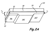
- FIGS. 2A and 2B illustrate a first embodiment in which blade outer air seal 20 includes substrate 30, and abradable coating 22 includes bond coat 32, and thermal barrier coating 34.
- FIG. 2A shows blade outer air seal 20 before turbine 10 is operated and abrasion of TBC 34 in the blade rub path has occurred.
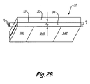
- FIG. 2B shows blade outer air seal 20 after turbine 10 has run and abrasion of TBC 34 has established a final thickness of TBC 34 in the blade rub path.
- TBC 34 includes leading portion 34L and trailing portion 34T of thickness t 1 , and central portion 34C of greater thickness t 2 .
- the TBC may be deposited as a uniform thickness layer of thickness t 2 , and leading and trailing portions 34L and 34T can then be formed by selective removal using abrasive grinding, milling, lapping, water jetting, laser removal, single or multipoint turning, or other removal techniques, so that central portion 34C extends radially inward with respect to leading and trailing portions 34L and 34T.
- central portion 34C may be deposited to a greater thickness using controlled spraying or masking processes.
- Thickness t 1 is determined to be the thickness necessary to create a clearance fit between TBC 34 and the turbine blade tip T when blade outer air seal 20 is secured by support section 18 to outer case 16.
- acceptable industry standards for the clearance distance between the blade outer air seal 20 and turbine blade tip T is between about 0.025 mm (1 mil) and about 1.27 mm (50 mils).
- Central portion 34C of TBC 34 is initially left proud with a radial thickness t 2 greater than thickness t 1 .
- Central portion 34C is located so that it will be within the blade rub path of turbine blade 12. This blade rub path is created by motion of turbine blade 12 in the circumferential direction along TBC 34 relative to stationary blade outer air seal 20.
- the radial thickness t 1 required for the leading and trailing portions 34L, 34T can be predetermined by modeling factors such as turbine blade expansion or blade outer air seal abradable loss under turbine operating conditions (i.e. temperature and pressure). Alternatively radial thickness t 1 can be predetermined during repair or replacement by measuring turbine blade 12 rub depth along the turbine rub path of the blade outer seal 20 being repaired or replaced.
- FIG. 2B illustrates blade outer air seal 20 after initial service use of the gas turbine engine 10.
- the greater thickness of central portion 34C (shown in FIG. 2A ) has been reduced by rotation of turbine blade 12 relative to the blade outer air seal 20.
- Blade rub portion 34R of TBC 34 now has a radial thickness t 3 similar to or identical to thickness t 1 of leading portion 34L and trailing portion 34T.
- This radial thickness t 1 is typically the thickness necessary to create a clearance fit between TBC 34 and turbine blade tip T during normal service use of the turbine 10.
- variations between the radial thickness t 1 of leading and trailing portions 34L and 34T and radial thickness t 3 of blade rub portion 34R of between about 0.025 mm (1 mil) and about 0.125 mm (5mil) may be achieved. In other embodiments, variations may occur depending on the type of TBC utilized, for example a variation between t 1 and t 3 of greater than about 0.125mm (5mil) may be experienced when a zirconia based ceramic is utilized. Variations of less than about 0.025 mm (1mil) between the radial thickness t 1 of leading and trailing portions 34L and 34T and radial thickness t 3 of blade rub portion 34R are also possible.
- the resulting TBC 34 has substantially uniform radial thickness.
- the geometric uniformity of TBC 34 leads to reduced thermal gradients in the blade outer air seal 20, reduced heat transfer, and reduced thermal-mechanical fatigue.
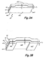
- FIGS. 3A and 3B show another embodiment of blade outer air seal 20.
- the blade outer air seal 20 includes substrate 60, bond coat 62 and TBC 64, and substrate 60 has a circumferentially extending central depression 60C.
- TBC 64 has an outer surface profile that is generally flat prior to service use, so that leading portion 64L and trailing portion 64T have a thickness t 1 while central portion 64C has a greater thickness t 2 .
- the TBC 64 is initially deposited with a substantially uniform outer surface but with differing thicknesses t 1 and t 2 .
- the outer surface of TBC 64 may initially be formed to follow the contour of substrate 60, for example, and a material removal process performed such as lapping or grinding after TBC 64 has been deposited. Alternatively, deposition of TBC 64 can be varied to produce areas of different thickness as shown in FIG 3A .
- FIG. 3B illustrates blade outer air seal 20 of FIG. 3A after initial service use of gas turbine 10.
- blade rub portion 64R material has been removed by radial and thermal interaction of turbine blade 12 relative to static blade outer air seal 20.
- Blade rub portion 64R (which is located in what was the thicker central portion 64C of TBC 64 in FIG. 3A ) has a radial thickness t 3 similar to or identical to that of the radial thickness t 1 of leading portion 64L and trailing portion 64T. Because of the similarity in thicknesses t 1 and t 3 of TBC 64 after blade rub portion 64R has formed, blade outer air seal 20 receives a more uniform heat flux.
- the abradable protective coating e.g. a TBC
- the abradable protective coating e.g. a TBC
- a more uniform thickness TBC is achieved during service use.
- thermal-mechanical cracking and associated stresses in the blade outer air seal 20 can be reduced. This helps to prevent the base metal of the blade outer air seal from being exposed in the blade path, and therefore, reduce heat transfer, thermal gradients and thermal-mechanical fatigue later in engine life after there has been TBC thickness loss by erosion.
Landscapes
- Engineering & Computer Science (AREA)
- Mechanical Engineering (AREA)
- General Engineering & Computer Science (AREA)
- Turbine Rotor Nozzle Sealing (AREA)
Applications Claiming Priority (1)
| Application Number | Priority Date | Filing Date | Title |
|---|---|---|---|
| US11/977,579 US8100640B2 (en) | 2007-10-25 | 2007-10-25 | Blade outer air seal with improved thermomechanical fatigue life |
Publications (3)
| Publication Number | Publication Date |
|---|---|
| EP2053202A2 true EP2053202A2 (de) | 2009-04-29 |
| EP2053202A3 EP2053202A3 (de) | 2012-02-01 |
| EP2053202B1 EP2053202B1 (de) | 2017-09-27 |
Family
ID=40202174
Family Applications (1)
| Application Number | Title | Priority Date | Filing Date |
|---|---|---|---|
| EP08253487.6A Active EP2053202B1 (de) | 2007-10-25 | 2008-10-27 | Außendichtung für eine Turbinenschaufel mit verbesserter thermomechanischen Ermüdungsbeständigkeit |
Country Status (2)
| Country | Link |
|---|---|
| US (1) | US8100640B2 (de) |
| EP (1) | EP2053202B1 (de) |
Cited By (2)
| Publication number | Priority date | Publication date | Assignee | Title |
|---|---|---|---|---|
| WO2015073321A1 (en) * | 2013-11-13 | 2015-05-21 | United Technologies Corporation | Turbomachinery blade outer air seal |
| FR3100048A1 (fr) * | 2019-08-23 | 2021-02-26 | Safran Ceramics | Anneau de turbine en CMC avec revêtement de protection à épaisseur variable et procédé de fabrication d’un tel anneau |
Families Citing this family (19)
| Publication number | Priority date | Publication date | Assignee | Title |
|---|---|---|---|---|
| US20110086163A1 (en) * | 2009-10-13 | 2011-04-14 | Walbar Inc. | Method for producing a crack-free abradable coating with enhanced adhesion |
| US9062558B2 (en) | 2011-07-15 | 2015-06-23 | United Technologies Corporation | Blade outer air seal having partial coating |
| US9995165B2 (en) | 2011-07-15 | 2018-06-12 | United Technologies Corporation | Blade outer air seal having partial coating |
| US9080459B2 (en) | 2012-01-03 | 2015-07-14 | General Electric Company | Forward step honeycomb seal for turbine shroud |
| US10215033B2 (en) * | 2012-04-18 | 2019-02-26 | General Electric Company | Stator seal for turbine rub avoidance |
| US9464536B2 (en) | 2012-10-18 | 2016-10-11 | General Electric Company | Sealing arrangement for a turbine system and method of sealing between two turbine components |
| US9833869B2 (en) | 2013-02-11 | 2017-12-05 | United Technologies Corporation | Blade outer air seal surface |
| US9957826B2 (en) | 2014-06-09 | 2018-05-01 | United Technologies Corporation | Stiffness controlled abradeable seal system with max phase materials and methods of making same |
| GB201410264D0 (en) * | 2014-06-10 | 2014-07-23 | Rolls Royce Plc | An assembly |
| US10132185B2 (en) | 2014-11-07 | 2018-11-20 | Rolls-Royce Corporation | Additive process for an abradable blade track used in a gas turbine engine |
| US20160201498A1 (en) * | 2014-12-15 | 2016-07-14 | United Technologies Corporation | Seal coating |
| EP3088672A1 (de) * | 2015-04-27 | 2016-11-02 | Siemens Aktiengesellschaft | Verfahren zum entwurf einer strömungsmaschine sowie strömungsmaschine |
| US10443426B2 (en) | 2015-12-17 | 2019-10-15 | United Technologies Corporation | Blade outer air seal with integrated air shield |
| US10213883B2 (en) | 2016-02-22 | 2019-02-26 | General Electric Company | System and method for in situ repair of gas turbine engine casing clearance |
| US11181002B2 (en) * | 2016-09-29 | 2021-11-23 | General Electric Company | Turbine systems with sealing components |
| US10823412B2 (en) | 2017-04-03 | 2020-11-03 | Raytheon Technologies Corporation | Panel surface pockets for coating retention |
| US10900371B2 (en) | 2017-07-27 | 2021-01-26 | Rolls-Royce North American Technologies, Inc. | Abradable coatings for high-performance systems |
| US10858950B2 (en) | 2017-07-27 | 2020-12-08 | Rolls-Royce North America Technologies, Inc. | Multilayer abradable coatings for high-performance systems |
| US10808565B2 (en) * | 2018-05-22 | 2020-10-20 | Rolls-Royce Plc | Tapered abradable coatings |
Citations (2)
| Publication number | Priority date | Publication date | Assignee | Title |
|---|---|---|---|---|
| US5439348A (en) | 1994-03-30 | 1995-08-08 | United Technologies Corporation | Turbine shroud segment including a coating layer having varying thickness |
| EP0965730A2 (de) | 1998-06-18 | 1999-12-22 | United Technologies Corporation | Gegenstand mit einer abriebesten Beschichtung sowie mit einer örtlich abreibbaren Beschichtung |
Family Cites Families (14)
| Publication number | Priority date | Publication date | Assignee | Title |
|---|---|---|---|---|
| US4422648A (en) | 1982-06-17 | 1983-12-27 | United Technologies Corporation | Ceramic faced outer air seal for gas turbine engines |
| US4566700A (en) | 1982-08-09 | 1986-01-28 | United Technologies Corporation | Abrasive/abradable gas path seal system |
| FR2558900B1 (fr) | 1984-02-01 | 1988-05-27 | Snecma | Dispositif d'etancheite peripherique d'aubage de compresseur axial |
| US4936745A (en) | 1988-12-16 | 1990-06-26 | United Technologies Corporation | Thin abradable ceramic air seal |
| US5022816A (en) | 1989-10-24 | 1991-06-11 | United Technologies Corporation | Gas turbine blade shroud support |
| US5603603A (en) | 1993-12-08 | 1997-02-18 | United Technologies Corporation | Abrasive blade tip |
| US5423659A (en) | 1994-04-28 | 1995-06-13 | United Technologies Corporation | Shroud segment having a cut-back retaining hook |
| US5791871A (en) | 1996-12-18 | 1998-08-11 | United Technologies Corporation | Turbine engine rotor assembly blade outer air seal |
| US6146089A (en) | 1998-11-23 | 2000-11-14 | General Electric Company | Fan containment structure having contoured shroud for optimized tip clearance |
| US6350102B1 (en) | 2000-07-19 | 2002-02-26 | General Electric Company | Shroud leakage flow discouragers |
| US6670046B1 (en) * | 2000-08-31 | 2003-12-30 | Siemens Westinghouse Power Corporation | Thermal barrier coating system for turbine components |
| US6537021B2 (en) | 2001-06-06 | 2003-03-25 | Chromalloy Gas Turbine Corporation | Abradeable seal system |
| FR2832180B1 (fr) * | 2001-11-14 | 2005-02-18 | Snecma Moteurs | Revetement abradable pour parois de turbines a gaz |
| JP2006104577A (ja) * | 2004-10-04 | 2006-04-20 | United Technol Corp <Utc> | セグメント化ガドリニアジルコニア被膜およびその形成方法、セグメント化セラミック被覆システムならびに被膜部品 |
-
2007
- 2007-10-25 US US11/977,579 patent/US8100640B2/en active Active
-
2008
- 2008-10-27 EP EP08253487.6A patent/EP2053202B1/de active Active
Patent Citations (2)
| Publication number | Priority date | Publication date | Assignee | Title |
|---|---|---|---|---|
| US5439348A (en) | 1994-03-30 | 1995-08-08 | United Technologies Corporation | Turbine shroud segment including a coating layer having varying thickness |
| EP0965730A2 (de) | 1998-06-18 | 1999-12-22 | United Technologies Corporation | Gegenstand mit einer abriebesten Beschichtung sowie mit einer örtlich abreibbaren Beschichtung |
Cited By (3)
| Publication number | Priority date | Publication date | Assignee | Title |
|---|---|---|---|---|
| WO2015073321A1 (en) * | 2013-11-13 | 2015-05-21 | United Technologies Corporation | Turbomachinery blade outer air seal |
| US10280783B2 (en) | 2013-11-13 | 2019-05-07 | United Technologies Corporation | Turbomachinery blade outer air seal |
| FR3100048A1 (fr) * | 2019-08-23 | 2021-02-26 | Safran Ceramics | Anneau de turbine en CMC avec revêtement de protection à épaisseur variable et procédé de fabrication d’un tel anneau |
Also Published As
| Publication number | Publication date |
|---|---|
| EP2053202A3 (de) | 2012-02-01 |
| US8100640B2 (en) | 2012-01-24 |
| EP2053202B1 (de) | 2017-09-27 |
| US20090110536A1 (en) | 2009-04-30 |
Similar Documents
| Publication | Publication Date | Title |
|---|---|---|
| EP2053202B1 (de) | Außendichtung für eine Turbinenschaufel mit verbesserter thermomechanischen Ermüdungsbeständigkeit | |
| US4914794A (en) | Method of making an abradable strain-tolerant ceramic coated turbine shroud | |
| EP2494210B1 (de) | Maschine mit schleifbaren leisten und verfahren | |
| US20090142548A1 (en) | Air cooled gas turbine components and methods of manufacturing and repairing the same | |
| US20080014094A1 (en) | Coated bucket damper pin | |
| US12460555B2 (en) | Substrate edge configurations for ceramic coatings | |
| US11319829B2 (en) | Geometrically segmented abradable ceramic thermal barrier coating with improved spallation resistance | |
| CN105443165B (zh) | 可磨耗密封件及用于形成可磨耗密封件的方法 | |
| EP2982831B1 (de) | Geometrisch segmentierte beschichtung auf gekrümmten oberflächen | |
| US20160281204A1 (en) | Thermal barrier coating repair | |
| US20200095666A1 (en) | Abradable coating | |
| EP3725909A1 (de) | Geometrisch segmentierte wärmedämmschicht mit splitterunterbrechermerkmalen | |
| EP3161268B1 (de) | Gasturbinenanlage mit einem ueberleitkanal und zugehöriges herstellungsverfahren eines ueberleitkanals | |
| US20220349312A1 (en) | Hybrid Thermal Barrier Coating | |
| US20250243770A1 (en) | Internal aluminide coating for vanes and blades and method of manufacture | |
| EP2574545A2 (de) | Verschleißfeste Beschichtung und Verwendung davon | |
| EP4636224A1 (de) | Geometrisch segmentierte beschichtung zur wärmedämmung und abreibbarkeitsschutz | |
| US20260110096A1 (en) | Turbine blade outermost abrasive layer using graded ceramics |
Legal Events
| Date | Code | Title | Description |
|---|---|---|---|
| PUAI | Public reference made under article 153(3) epc to a published international application that has entered the european phase |
Free format text: ORIGINAL CODE: 0009012 |
|
| AK | Designated contracting states |
Kind code of ref document: A2 Designated state(s): AT BE BG CH CY CZ DE DK EE ES FI FR GB GR HR HU IE IS IT LI LT LU LV MC MT NL NO PL PT RO SE SI SK TR |
|
| AX | Request for extension of the european patent |
Extension state: AL BA MK RS |
|
| PUAL | Search report despatched |
Free format text: ORIGINAL CODE: 0009013 |
|
| AK | Designated contracting states |
Kind code of ref document: A3 Designated state(s): AT BE BG CH CY CZ DE DK EE ES FI FR GB GR HR HU IE IS IT LI LT LU LV MC MT NL NO PL PT RO SE SI SK TR |
|
| AX | Request for extension of the european patent |
Extension state: AL BA MK RS |
|
| RIC1 | Information provided on ipc code assigned before grant |
Ipc: F01D 11/12 20060101AFI20111223BHEP |
|
| 17P | Request for examination filed |
Effective date: 20120801 |
|
| AKX | Designation fees paid |
Designated state(s): DE GB |
|
| 17Q | First examination report despatched |
Effective date: 20160405 |
|
| RAP1 | Party data changed (applicant data changed or rights of an application transferred) |
Owner name: UNITED TECHNOLOGIES CORPORATION |
|
| GRAP | Despatch of communication of intention to grant a patent |
Free format text: ORIGINAL CODE: EPIDOSNIGR1 |
|
| STAA | Information on the status of an ep patent application or granted ep patent |
Free format text: STATUS: GRANT OF PATENT IS INTENDED |
|
| INTG | Intention to grant announced |
Effective date: 20170420 |
|
| GRAS | Grant fee paid |
Free format text: ORIGINAL CODE: EPIDOSNIGR3 |
|
| GRAA | (expected) grant |
Free format text: ORIGINAL CODE: 0009210 |
|
| STAA | Information on the status of an ep patent application or granted ep patent |
Free format text: STATUS: THE PATENT HAS BEEN GRANTED |
|
| AK | Designated contracting states |
Kind code of ref document: B1 Designated state(s): DE GB |
|
| REG | Reference to a national code |
Ref country code: GB Ref legal event code: FG4D |
|
| REG | Reference to a national code |
Ref country code: DE Ref legal event code: R096 Ref document number: 602008052240 Country of ref document: DE |
|
| REG | Reference to a national code |
Ref country code: DE Ref legal event code: R097 Ref document number: 602008052240 Country of ref document: DE |
|
| PLBE | No opposition filed within time limit |
Free format text: ORIGINAL CODE: 0009261 |
|
| STAA | Information on the status of an ep patent application or granted ep patent |
Free format text: STATUS: NO OPPOSITION FILED WITHIN TIME LIMIT |
|
| 26N | No opposition filed |
Effective date: 20180628 |
|
| REG | Reference to a national code |
Ref country code: DE Ref legal event code: R081 Ref document number: 602008052240 Country of ref document: DE Owner name: RAYTHEON TECHNOLOGIES CORPORATION (N.D.GES.D.S, US Free format text: FORMER OWNER: UNITED TECHNOLOGIES CORPORATION, FARMINGTON, CONN., US Ref country code: DE Ref legal event code: R081 Ref document number: 602008052240 Country of ref document: DE Owner name: RTX CORPORATION (N.D.GES.D. STAATES DELAWARE),, US Free format text: FORMER OWNER: UNITED TECHNOLOGIES CORPORATION, FARMINGTON, CONN., US |
|
| P01 | Opt-out of the competence of the unified patent court (upc) registered |
Effective date: 20230519 |
|
| PGFP | Annual fee paid to national office [announced via postgrant information from national office to epo] |
Ref country code: GB Payment date: 20250923 Year of fee payment: 18 |
|
| REG | Reference to a national code |
Ref country code: DE Ref legal event code: R081 Ref document number: 602008052240 Country of ref document: DE Owner name: RTX CORPORATION (N.D.GES.D. STAATES DELAWARE),, US Free format text: FORMER OWNER: RAYTHEON TECHNOLOGIES CORPORATION (N.D.GES.D.STAATES DELAWARE), ARLINGTON, VA, US |
|
| PGFP | Annual fee paid to national office [announced via postgrant information from national office to epo] |
Ref country code: DE Payment date: 20250923 Year of fee payment: 18 |