EP2053228A2 - Bossage d'axe d'un piston - Google Patents
Bossage d'axe d'un piston Download PDFInfo
- Publication number
- EP2053228A2 EP2053228A2 EP08017698A EP08017698A EP2053228A2 EP 2053228 A2 EP2053228 A2 EP 2053228A2 EP 08017698 A EP08017698 A EP 08017698A EP 08017698 A EP08017698 A EP 08017698A EP 2053228 A2 EP2053228 A2 EP 2053228A2
- Authority
- EP
- European Patent Office
- Prior art keywords
- piston
- connecting rod
- pin
- curved
- anformung
- Prior art date
- Legal status (The legal status is an assumption and is not a legal conclusion. Google has not performed a legal analysis and makes no representation as to the accuracy of the status listed.)
- Withdrawn
Links
Images


Classifications
-
- F—MECHANICAL ENGINEERING; LIGHTING; HEATING; WEAPONS; BLASTING
- F02—COMBUSTION ENGINES; HOT-GAS OR COMBUSTION-PRODUCT ENGINE PLANTS
- F02F—CYLINDERS, PISTONS OR CASINGS, FOR COMBUSTION ENGINES; ARRANGEMENTS OF SEALINGS IN COMBUSTION ENGINES
- F02F3/00—Pistons
Definitions
- the invention relates to a particular cast from a lightweight metal material piston, which is intended for internal combustion engines.
- the connected via a connecting rod with a crankshaft of the internal combustion engine piston forms a piston skirt, which includes two diametrically opposed pin bosses.
- a hub bore is introduced, which is intended to receive a piston pin on which the connecting rod is articulated on the piston.
- the DE 198 37 596 C1 shows a light metal piston having the bearing of the piston pin rolled rolled metal bushes bearing bushes.
- the bearing bushes are shrunk or pressed into the hub bores in a position-oriented manner such that their butt joints are offset in the installed state relative to a piston longitudinal axis.
- Such bushings require an increased installation effort and a complex handling and defined shape tolerances to ensure a permanent tight fit.
- cast light metal piston is from the EP 0 270 139 A known to pour in the direction of the piston crown oriented fiber moldings in the hub bores. Apart from the fact that the fiber molding requires an increased effort in the machining of the hub bore, this measure does not lead to an increase in the structural strength in all voltage levels.
- the object of the present invention is to increase the load capacity of the piston pin bearing, in particular the pin boss by cost-effective measures.
- the solution of this problem consists in accordance with the features of claim 1 in an arrangement of the piston pin bearing, wherein the pin boss in an upper, the piston crown area facing the supporting surface of the piston pin increasing local Anformung, camber or approach forms.
- the Anformung invention simultaneously causes a prolonged apex line of the hub bore in the direction of a Pleuel technique or in the direction of the upper connecting rod.
- the locally enlarged support surface of the piston pin in the region of the upper vertex of the hub bore decisively reduces the surface pressure.
- an advantageously small distance from the connecting rod eye is realized in the upper apex region of the hub bore, in which the pivoting movement of the upper connecting rod eye has only a slight effect, because of the protrusion forming in the bolt axis direction.
- the shaping in the area of the hub bore is designed and dimensioned in such a way that a uniform stress distribution, ie an optimum structural strength, is established in all stress levels.
- the simple and inexpensive realizable measures of the invention cause a task-appropriate increased pin hub load and thus a high piston loads enduring support and storage of the piston pin.
- This measure significantly improves the stability of heavy-duty, made of light metal pistons, which are preferably used for performance-enhanced diesel internal combustion engines.
- the constructive, the hub bore partially extending inventive, the life of the piston increasing concept is inexpensive realized by a simple, not the casting process adaptation of the casting tool.
- the inventive measure, the piston load increasing measure further advantageously has no adverse effect on the piston weight, so that this piston can also be used in performance-enhanced and rotating at higher speeds internal combustion engines.
- a preferred embodiment of the invention provides that the Anformung the pin boss has a frontal rounded contour which extends at a distance from the envelope of the pivoting connecting rod. For this purpose, it lends itself to the curved or curved extending contour of Anformung rounded so designed that it is performed while maintaining a safe distance to close to the connecting rod or the connecting rod of the connecting rod.
- frontal curved or curved also to be designated as a bulge or approach, inventive Anformung determined by the pivoting range of the connecting rod envelope of the connecting rod. This measure allows over the entire width of the pin boss, that is a virtually unchanged optimal low pitch of the pivoted Pleuelauges between the frontal contour of the Anformung and the envelope adjusts.
- the invention further includes a locally reduce the distances between the Anformung and the connecting rod.
- This measure lends itself, for example, to take into account special structural conditions of the connecting rod eye.
- FIG. 1 shows a piston 1 in a longitudinal section, which is made as a cast piston made of light metal.
- a piston head 2 of the piston 1 which comprises a combustion chamber trough 3, a ring field 4 and a piston skirt 5 adjoin the outside.
- the ring field 4 is for receiving in FIG. 1 not shown piston rings.
- the piston shaft 5 forms two diametrically opposite, each a hub bore 7 enclosing pin bosses 6.
- the piston 1 is pivotally connected to a connecting rod 8.
- a piston pin 9 is inserted floatingly mounted in the bore hole to be designated as a pin bore 7, which is simultaneously guided by a receptacle 10 of a connecting rod 11.
- each pin boss 6 forms above the hub bore 7, aligned with the piston head 2, a support surface 13 projecting axially in the direction of a connecting rod receptacle 12.
- the support surface 13 designed as a local bulge or molding 14 lengthens a apex line in the region of a hub peak 15 of the hub bore 7, thereby reducing a self-adjusting surface pressure between the piston pin 9 and the hub bore 7 at the same time.
- the projections 14 reduce a hub distance "L", which is established between end faces 16 of the pin bosses 6 and also influences a fitting clearance between the end faces 16 and the connecting rod eye 11, which decreases from the dimension "S 1 " to "S 2 ".
- the sectional view according to FIG. 2 illustrates in particular the design of the Anformung 14 on the piston 1, with the in FIG. 1 illustrated piston 1 largely matches.
- the further description is therefore limited to the formation of Anformung 14, which adjoins the hub bore 7 and tapers like a dome inside the Pleuelability 12 to the piston head 2.
- the Anformung 14 marked with different shades of gray illustrates different design options.
- the one by the angle "a” designated area is limited to a narrow area on both sides of the crest line 15 of ⁇ 10 °.
- the much larger projection, designated " ⁇ " extends on both sides of the apex line 15 over an angle of ⁇ 80 °.
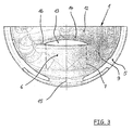
- FIG. 3 Shown partial view of the piston 1 on a piston interior 19 shows the support surface 13 in part as a circular segment.
- This illustration illustrates the largest axial extension of the support surface 13 in the region of a longitudinal axis 17 of the hub bore 7, according to FIG. 3 Starting from the maximum length of the supporting surface 13 supporting Anformung 14, this tapers continuously to a value that largely corresponds to a diameter of the hub bore 7.
- FIG. 4 shows various geometric shapes of the axially projecting Anformung 14 on the front side 16 of the pin boss 6 above the hub bore 7.
- the Anformung 14 denoted by “a” shows a curved running frontal course of Anformung 14.
- An alternative to the curved end face forms with "b” characterized Anformung 12.
- an envelope 18 of the connecting rod 11 is shown, which corresponds to a pivoting of the connecting rod 11.
- the distance measure “S 2 " illustrates the self-adjusting safety distance between the designated with "b” Anformung 14 and the envelope 18 of the connecting rod 11 in the operating state, which is constant over almost the entire travel or pivoting of the connecting rod 11.
Landscapes
- Engineering & Computer Science (AREA)
- Chemical & Material Sciences (AREA)
- Combustion & Propulsion (AREA)
- Mechanical Engineering (AREA)
- General Engineering & Computer Science (AREA)
- Pistons, Piston Rings, And Cylinders (AREA)
Applications Claiming Priority (1)
| Application Number | Priority Date | Filing Date | Title |
|---|---|---|---|
| DE102007050516 | 2007-10-23 |
Publications (2)
| Publication Number | Publication Date |
|---|---|
| EP2053228A2 true EP2053228A2 (fr) | 2009-04-29 |
| EP2053228A3 EP2053228A3 (fr) | 2014-12-10 |
Family
ID=40044118
Family Applications (1)
| Application Number | Title | Priority Date | Filing Date |
|---|---|---|---|
| EP08017698.5A Withdrawn EP2053228A3 (fr) | 2007-10-23 | 2008-10-09 | Bossage d'axe d'un piston |
Country Status (2)
| Country | Link |
|---|---|
| EP (1) | EP2053228A3 (fr) |
| DE (1) | DE102008051089A1 (fr) |
Families Citing this family (1)
| Publication number | Priority date | Publication date | Assignee | Title |
|---|---|---|---|---|
| JP2020180573A (ja) * | 2019-04-25 | 2020-11-05 | 株式会社クボタ | ピストンとコンロッドの支承構造 |
Citations (5)
| Publication number | Priority date | Publication date | Assignee | Title |
|---|---|---|---|---|
| JPS59120755A (ja) * | 1982-12-27 | 1984-07-12 | Toyota Motor Corp | 内燃機関用ピストン |
| DE3609019C1 (en) | 1986-03-18 | 1987-09-10 | Mahle Gmbh | Method for the production of the hub hole of a trunk piston, particularly for internal combustion engines |
| EP0270139A1 (fr) | 1986-11-21 | 1988-06-08 | KOLBENSCHMIDT Aktiengesellschaft | Piston léger pour moteurs à combustion interne |
| DE3840841A1 (de) | 1988-12-03 | 1990-06-07 | Kolbenschmidt Ag | Leichtmetallkolben fuer brennkraftmaschinen |
| DE19837596C1 (de) | 1998-08-19 | 2000-01-05 | Ks Kolbenschmidt Gmbh | Kolben für Verbrennungskraftmaschinen |
Family Cites Families (2)
| Publication number | Priority date | Publication date | Assignee | Title |
|---|---|---|---|---|
| JPS56167831A (en) * | 1980-05-28 | 1981-12-23 | Yanmar Diesel Engine Co Ltd | Piston for internal combustion engine |
| JPS6198948A (ja) * | 1984-10-22 | 1986-05-17 | Toyota Motor Corp | 内燃機関用ピストン |
-
2008
- 2008-10-09 EP EP08017698.5A patent/EP2053228A3/fr not_active Withdrawn
- 2008-10-09 DE DE102008051089A patent/DE102008051089A1/de active Pending
Patent Citations (5)
| Publication number | Priority date | Publication date | Assignee | Title |
|---|---|---|---|---|
| JPS59120755A (ja) * | 1982-12-27 | 1984-07-12 | Toyota Motor Corp | 内燃機関用ピストン |
| DE3609019C1 (en) | 1986-03-18 | 1987-09-10 | Mahle Gmbh | Method for the production of the hub hole of a trunk piston, particularly for internal combustion engines |
| EP0270139A1 (fr) | 1986-11-21 | 1988-06-08 | KOLBENSCHMIDT Aktiengesellschaft | Piston léger pour moteurs à combustion interne |
| DE3840841A1 (de) | 1988-12-03 | 1990-06-07 | Kolbenschmidt Ag | Leichtmetallkolben fuer brennkraftmaschinen |
| DE19837596C1 (de) | 1998-08-19 | 2000-01-05 | Ks Kolbenschmidt Gmbh | Kolben für Verbrennungskraftmaschinen |
Also Published As
| Publication number | Publication date |
|---|---|
| DE102008051089A1 (de) | 2009-04-30 |
| EP2053228A3 (fr) | 2014-12-10 |
Similar Documents
| Publication | Publication Date | Title |
|---|---|---|
| EP0171566B1 (fr) | Pistons pour moteurs à combustion interne | |
| DE60301636T2 (de) | Kolben | |
| DE3621421C1 (de) | Kolbenmaschine | |
| DE69404992T2 (de) | Kolbenzusammenbau mit verteilter belastung und zentral befestigten kolbenbolzen | |
| DE102007018932A1 (de) | Belastungsoptimierter Innenraum eines Kolbens | |
| EP0714485B1 (fr) | Piston en metal leger pour moteurs a combustion interne tres sollicites | |
| DE2253868A1 (de) | Einteiliger, mit einer pleuelstange verbundener kolben | |
| EP0189767B1 (fr) | Piston à plusieurs parties, refroidi par de l'huile, pour moteurs à combustion interne à piston alternatif | |
| DE3210771A1 (de) | Kolbentrieb fuer hubkolben-brennkraftmaschinen, wie dieselmotoren u.a. | |
| EP0643216B1 (fr) | Palier de vilebrequin | |
| DE4314892A1 (de) | Bolzenstopfen zur Verwendung in einer Kolbenanordnung | |
| WO1996007841A1 (fr) | Piston en metal leger pour moteurs a combustion interne fortement sollicites | |
| EP3334918B1 (fr) | Piston pour moteur à combustion interne | |
| EP2663760A1 (fr) | Piston à utiliser dans des moteurs à combustion interne | |
| DE69506386T2 (de) | Achse für zweiteiligen kolben | |
| DE3609019C1 (en) | Method for the production of the hub hole of a trunk piston, particularly for internal combustion engines | |
| WO2010142389A1 (fr) | Piston en métal léger à bol de combustion multi-cavité | |
| WO2003098078A1 (fr) | Paliers d'axe de piston pour moteurs a combustion interne | |
| EP2053228A2 (fr) | Bossage d'axe d'un piston | |
| DE10130253A1 (de) | Gleitlager, insbesondere einer Pleuelstange für Hubkolbenbrennkraftmaschinen | |
| DE10101605B4 (de) | Kolben für Brennkraftmaschinen | |
| DE19916492A1 (de) | Kurbelwelle für eine Brennkraftmaschine | |
| DE3932563A1 (de) | Leichtmetallkolben fuer verbrennungskraftmaschinen | |
| EP1920174B1 (fr) | Geometrie d'alesage d'axe de piston continue destinee a un piston d'un moteur a combustion interne | |
| EP0254340A2 (fr) | Piston pour une machine à pistons |
Legal Events
| Date | Code | Title | Description |
|---|---|---|---|
| PUAI | Public reference made under article 153(3) epc to a published international application that has entered the european phase |
Free format text: ORIGINAL CODE: 0009012 |
|
| AK | Designated contracting states |
Kind code of ref document: A2 Designated state(s): AT BE BG CH CY CZ DE DK EE ES FI FR GB GR HR HU IE IS IT LI LT LU LV MC MT NL NO PL PT RO SE SI SK TR |
|
| AX | Request for extension of the european patent |
Extension state: AL BA MK RS |
|
| PUAL | Search report despatched |
Free format text: ORIGINAL CODE: 0009013 |
|
| AK | Designated contracting states |
Kind code of ref document: A3 Designated state(s): AT BE BG CH CY CZ DE DK EE ES FI FR GB GR HR HU IE IS IT LI LT LU LV MC MT NL NO PL PT RO SE SI SK TR |
|
| AX | Request for extension of the european patent |
Extension state: AL BA MK RS |
|
| RIC1 | Information provided on ipc code assigned before grant |
Ipc: F02F 3/00 20060101AFI20141106BHEP Ipc: F16J 1/02 20060101ALI20141106BHEP |
|
| 17P | Request for examination filed |
Effective date: 20150603 |
|
| RBV | Designated contracting states (corrected) |
Designated state(s): AT BE BG CH CY CZ DE DK EE ES FI FR GB GR HR HU IE IS IT LI LT LU LV MC MT NL NO PL PT RO SE SI SK TR |
|
| AKX | Designation fees paid |
Designated state(s): AT BE BG CH CY CZ DE DK EE ES FI FR GB GR HR HU IE IS IT LI LT LU LV MC MT NL NO PL PT RO SE SI SK TR |
|
| AXX | Extension fees paid |
Extension state: RS Extension state: BA Extension state: MK Extension state: AL |
|
| STAA | Information on the status of an ep patent application or granted ep patent |
Free format text: STATUS: EXAMINATION IS IN PROGRESS |
|
| 17Q | First examination report despatched |
Effective date: 20171129 |
|
| STAA | Information on the status of an ep patent application or granted ep patent |
Free format text: STATUS: THE APPLICATION IS DEEMED TO BE WITHDRAWN |
|
| 18D | Application deemed to be withdrawn |
Effective date: 20210208 |