EP2053252B1 - Hydraulikanordnung zum Ansteuern zumindest einer Komponente eines Fahrzeuges - Google Patents
Hydraulikanordnung zum Ansteuern zumindest einer Komponente eines Fahrzeuges Download PDFInfo
- Publication number
- EP2053252B1 EP2053252B1 EP08017112.7A EP08017112A EP2053252B1 EP 2053252 B1 EP2053252 B1 EP 2053252B1 EP 08017112 A EP08017112 A EP 08017112A EP 2053252 B1 EP2053252 B1 EP 2053252B1
- Authority
- EP
- European Patent Office
- Prior art keywords
- housing
- piston
- hydraulic arrangement
- piston rod
- arrangement according
- Prior art date
- Legal status (The legal status is an assumption and is not a legal conclusion. Google has not performed a legal analysis and makes no representation as to the accuracy of the status listed.)
- Not-in-force
Links
Images

Classifications
-
- F—MECHANICAL ENGINEERING; LIGHTING; HEATING; WEAPONS; BLASTING
- F15—FLUID-PRESSURE ACTUATORS; HYDRAULICS OR PNEUMATICS IN GENERAL
- F15B—SYSTEMS ACTING BY MEANS OF FLUIDS IN GENERAL; FLUID-PRESSURE ACTUATORS, e.g. SERVOMOTORS; DETAILS OF FLUID-PRESSURE SYSTEMS, NOT OTHERWISE PROVIDED FOR
- F15B7/00—Systems in which the movement produced is definitely related to the output of a volumetric pump; Telemotors
- F15B7/06—Details
- F15B7/08—Input units; Master units
-
- F—MECHANICAL ENGINEERING; LIGHTING; HEATING; WEAPONS; BLASTING
- F16—ENGINEERING ELEMENTS AND UNITS; GENERAL MEASURES FOR PRODUCING AND MAINTAINING EFFECTIVE FUNCTIONING OF MACHINES OR INSTALLATIONS; THERMAL INSULATION IN GENERAL
- F16D—COUPLINGS FOR TRANSMITTING ROTATION; CLUTCHES; BRAKES
- F16D25/00—Fluid-actuated clutches
- F16D25/08—Fluid-actuated clutches with fluid-actuated member not rotating with a clutching member
-
- F—MECHANICAL ENGINEERING; LIGHTING; HEATING; WEAPONS; BLASTING
- F16—ENGINEERING ELEMENTS AND UNITS; GENERAL MEASURES FOR PRODUCING AND MAINTAINING EFFECTIVE FUNCTIONING OF MACHINES OR INSTALLATIONS; THERMAL INSULATION IN GENERAL
- F16D—COUPLINGS FOR TRANSMITTING ROTATION; CLUTCHES; BRAKES
- F16D25/00—Fluid-actuated clutches
- F16D25/08—Fluid-actuated clutches with fluid-actuated member not rotating with a clutching member
- F16D2025/081—Hydraulic devices that initiate movement of pistons in secondary cylinders for actuating clutches, i.e. primary cylinders
Definitions
- the present invention relates to a hydraulic system for driving at least one component of a vehicle according to the preamble of claim 1.
- the present invention relates to a hydraulic arrangement with a master cylinder comprising a pressure chamber formed in its housing, in which a displaceable piston is movable, wherein Limiting the extension movement of the piston, at least one stop is provided, which cooperates with a piston-side stop.
- a hydraulic system for a motor vehicle comprising a master cylinder with a housing and a piston arranged axially displaceably in this.
- the piston delimits a filled with a hydraulic fluid pressure chamber and is axially displaced upon actuation of the master cylinder by means of a piston rod acting on the piston, wherein the piston rod is connected via a ball joint with the piston.
- the pressure chamber of the master cylinder is connected via a pressure line with a slave cylinder. With the slave cylinder a releaser of a clutch is actuated via a release mechanism.
- a stop plate is arranged on the side facing away from the piston of the ball joint.
- the movement of the piston is limited by a retaining clip backwards by the stopper plate abuts the retaining clip. In this way, an effective in the pulling direction stop exists.
- the retaining clip is attached in the known hydraulic arrangement to a welding ring. The welding ring in turn receives the piston for axial guidance and is welded to the housing.
- the piston rod of the master cylinder has to transmit a pull-out force of up to 1500 Newtons.
- This pull-out force is transmitted through the stop or the retaining clip and the welding ring on the housing. Therefore, the weld must be made very robust in the known hydraulic arrangement, so that destruction of this compound is prevented in extreme pedal operations.
- a hydraulic system according to the preamble of claim 1 is known from DE 103 51 907 A1 known.
- the present invention is based on the object to propose a hydraulic system of the type described above, which ensures the safest possible operation and in the installation space and installation adjustments without extensive changes are possible.
- the housing is designed in several parts, the pull-out force is absorbed, for example, in a pedal stop directly from the housing parts.
- the connection between the welding ring and the housing is not acted upon by the pull-out force, so that this connection does not have to be made additionally robust.
- the welding ring as an inner component in a space or installation adjustment does not need to be adjusted. This results in a significant reduction of the required modification effort, since only the housing parts may be changed as external parts.
- the welding ring can be standardized, so as to be able to save development costs and development time. Any change requests to the master cylinder can be carried out quickly, because only the housing is provided as an outer part.
- the housing part associated with the piston rod has recesses or the like in the radial direction for receiving a retaining element.
- the housing part is connected to an additional holding element in order to jointly form the housing-side stop area.
- the holding element may extend in the radial direction through the housing.
- the retaining element can be releasably retained in recesses or the like of the housing. In this case, for example, positive or non-positive connections can be used.
- the holding element is preferably designed as a roughly U-shaped retaining clip or the like.
- the retaining clip for example, can be inserted radially through the housing part associated with the piston rod in the region of the piston rod, thus forming a housing-side stop region for the piston.
- the two legs of the U-shaped retaining clip have a distance between each other, which is at least slightly smaller than the diameter of a stop plate designed as a piston-side stop. In this way, the two legs form a housing-side stop for the stop plate.
- the shape of the stop plate can be chosen arbitrarily.
- the stop plate may be attached to the piston rod. There are also other possible arrangements of the stop plate conceivable.
- the distance is at least slightly greater than the diameter of the piston rod.
- the piston rod associated with the housing part is releasably connected as a lid to the housing base part. It is also conceivable that further housing parts are provided. As a releasable connection may preferably be provided a snap ring connection or a bayonet closure. However, other types of connection are conceivable.
- the hydraulic system can preferably be used for driving a clutch.
- other applications are conceivable.
- the hydraulic arrangement comprises a master cylinder 1, which has a multi-part housing with a housing base part 2 and a further housing part 3 as cover. By the housing, a pressure chamber 16 is formed.
- a pressure medium connection 18 is arranged, which is connected to a pressure medium line, not shown, which leads to a slave cylinder also not shown for driving the clutch.
- the housing base part 2 and the housing part 3 are connected to each other via a detachable connection, for example via a snap-in connection or a bayonet closure.
- the connecting piece 4 is connected to a pressure medium reservoir, not shown, can run from the pressure medium.
- an axially displaceable piston 5 is arranged in the filled with a hydraulic fluid pressure chamber 16, an axially displaceable piston 5 is arranged.
- the piston 5 Upon actuation of the master cylinder 1, the piston 5 is displaced axially against the spring force of a return spring 9 via a piston rod 5 fastened to the piston 5, in order to produce a corresponding pressure in the slave cylinder for actuating the clutch applied.
- the axial movement of the piston 5 is supported by a welding ring 10 which is fixed to the housing 2.
- a stop plate 7 for limiting the extension movement of the piston 5, e.g. arranged on the piston rod 6 a stop plate 7 as a piston-side stop, which cooperates with a housing-side stop.
- the housing-side stop is realized by a stopper portion 15 on the housing part 3.
- the axial stop region 15 corresponds to the stop plate 7 designed as a piston-side stop, so that the retraction movement of the piston 5 is correspondingly limited.
- the stop area 15 also has an axial passage 17 for the piston rod 6.
- the passage 17 is formed as a slot whose width is at least slightly larger than the diameter of the piston rod 6 and at least slightly smaller than the diameter of the stop plate 7.
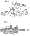
- the housing-side stop is in the embodiment according to the FIGS. 3 and 4 realized by a holding element which is connected to the housing part 3.
- the holding element is designed as an approximately U-shaped retaining clip 8.
- the retaining clip 8 is with their legs through corresponding recesses 13, 13 '; 14, 14 'guided at the top and at the bottom of the housing part 3 to extend radially through the housing part 3.
- the distance between the two legs is at least slightly smaller than the diameter of the stop plate 7, so that the extension movement of the piston 5 is limited. In this case, the distance between the two legs is slightly larger than the diameter of the piston rod 6 in order to allow the piston rod 6 to be freely movable between the legs.
- the retaining clip 8 is connected directly to the housing part 3 of the master cylinder 1, so that the pull-out force is transmitted upon reaching the stop directly from the retaining clip 8 to the housing.
- the assembly process is thereby hardly affected because the retaining clip 8 is inserted directly into the housing part 3.
- the housing part 3 provided as cover is fastened to the housing base part 2 via a detachable connection.
Landscapes
- Engineering & Computer Science (AREA)
- General Engineering & Computer Science (AREA)
- Mechanical Engineering (AREA)
- Physics & Mathematics (AREA)
- Fluid Mechanics (AREA)
- Hydraulic Clutches, Magnetic Clutches, Fluid Clutches, And Fluid Joints (AREA)
- Transmission Of Braking Force In Braking Systems (AREA)
Description
- Die vorliegende Erfindung betrifft eine Hydraulikanordnung zum Ansteuern zumindest einer Komponente eines Fahrzeuges gemäß dem Oberbegriff des Patentanspruchs 1. Insbesondere betrifft die vorliegende Erfindung eine Hydraulikanordnung mit einem Geberzylinder, der einen in seinem Gehäuse gebildeten Druckraum umfasst, in dem ein verschiebbarer Kolben bewegbar ist, wobei zur Begrenzung der Auszugbewegung des Kolbens zumindest ein Anschlag vorgesehen ist, der mit einem kolbenseitigen Anschlag zusammen wirkt.
- Beispielsweise aus der Druckschrift
DE 103 27 437 A1 ist ein hydraulisches System für ein Kraftfahrzeug bekannt, umfassend einen Geberzylinder mit einem Gehäuse und einem in diesem axial verschiebbar angeordneten Kolben. Der Kolben begrenzt einen mit einer Hydraulikflüssigkeit gefüllten Druckraum und wird bei Betätigung des Geberzylinders mittels einer auf den Kolben wirkenden Kolbenstange axial verschoben, wobei die Kolbenstange über ein Kugelgelenk mit dem Kolben verbunden ist. Der Druckraum des Geberzylinders wird ist über eine Druckleitung mit einem Nehmerzylinder verbunden. Mit dem Nehmerzylinder wird über eine Ausrückmechanik ein Ausrücker einer Kupplung betätigt. - Um die Bewegung des Kolbens begrenzen zu können, ist an der dem Kolben abgewandten Seite des Kugelgelenkes ein Anschlagteller angeordnet. Die Bewegung des Kolbens wird durch eine Halteklammer rückwärts begrenzt, indem der Anschlagteller an die Halteklammer anstößt. Auf diese Weise ist ein in Zugrichtung wirksamer Anschlag vorhanden. Die Halteklammer ist bei der bekannten Hydraulikanordnung an einem Schweißring befestigt. Der Schweißring wiederum nimmt den Kolben zur Axialführung auf und ist mit dem Gehäuse verschweißt.
- Üblicherweise muss die Kolbenstange des Geberzylinders eine Auszugkraft von bis zu 1500 Newton übertragen. Diese Auszugkraft wird durch den Anschlag beziehungsweise die Halteklammer und den Schweißring auf das Gehäuse weitergeleitet. Deshalb muss die Schweißverbindung sehr robust bei der bekannten Hydraulikanordnung ausgeführt sein, damit eine Zerstörung dieser Verbindung bei extremen Pedalbetätigungen verhindert wird.
- Ferner ergibt sich der Nachteil, dass aufgrund eventueller Bauraum- und Einbauanpassungen umfangreiche Änderungen an der Hydraulikanordnung erforderlich sind. Aufgrund der Verbindung einerseits zwischen dem Schweißring und dem Gehäuse sowie, andererseits zwischen den Schweißring und der Halteklammer sind Änderungen an zumindest den vorgenannten Bauteilen unvermeidbar. Dies erhöht die Herstellungskosten bei erforderlichen Anpassungen.
- Eine Hydraulikanordnung gemäß dem Oberbegriff des Patentanspruchs 1 ist aus der
DE 103 51 907 A1 bekannt. - Der vorliegenden Erfindung liegt die Aufgabe zu Grunde, eine Hydraulikanordnung der eingangs beschriebenen Gattung vorzuschlagen, welche einen möglichst sicheren Betrieb gewährleistet und bei der Bauraum- und Einbauanpassungen ohne umfangreiche Änderungen möglich sind.
- Diese Aufgabe wird erfindungsgemäß durch die Merkmale des Patentanspruches 1 gelöst. Weitere vorteilhafte Ausgestaltungen ergeben sich aus den Unteransprüchen und der Zeichnung.
- Somit wird eine Hydraulikanordnung zum Ansteuern zumindest einer Komponente, beispielsweise einer Kupplung eines Fahrzeuges mit einem Geberzylinder vorgeschlagen, der einen in seinem Gehäuse gebildeten Druckraum umfasst, in dem ein verschiebbarer Kolben (axial) bewegbar ist, wobei zur Begrenzung der Auszugbewegung des Kolbens zumindest ein Anschlag vorgesehen ist, welcher mit einem kolbenseitigen Anschlag zusammenwirkt, wobei das Gehäuse mehrteilig ausgebildet ist, wobei das einer Kolbenstange zugeordnete Gehäuseteil als gehäuseseitiger Anschlag vorgesehen ist. Aufgrund der Tatsache, dass das Gehäuse mehrteilig ausgebildet ist, wird die Auszugkraft zum Beispiel bei einem Pedalanschlag direkt von den Gehäuseteilen aufgenommen. Somit wird die Verbindung zwischen dem Schweißring und dem Gehäuse nicht mit der Auszugkraft beaufschlagt, so dass diese Verbindung nicht zusätzlich robust ausgestaltet werden muss. Zudem ergibt sich der Vorteil, dass der Schweißring als inneres Bauteil bei einer Bauraum- oder Einbauanpassung nicht angepasst werden muss. Daraus ergibt sich eine deutliche Reduzierung des erforderlichen Änderungsaufwandes, da lediglich die Gehäuseteile als Außenteile eventuell geändert werden.
- Somit kann der Schweißring standardisiert werden, um somit Entwicklungskosten und Entwicklungszeit einsparen zu können. Eventuelle Änderungswünsche an dem Geberzylinder können schnell durchgeführt werden, weil nur das Gehäuse als Außenteil vorgesehen ist.
- Das der Kolbenstange zugeordnete Gehäuseteil weist in radialer Richtung Ausnehmungen oder dergleichen zum Aufnehmen eines Halteelementes auf. Bei dieser Ausführungsvariante wird das Gehäuseteil mit einem zusätzlichen Halteelement verbunden, um gemeinsam den gehäuseseitigen Anschlagbereich zu bilden. Vorzugsweise kann sich das Halteelement in radialer Richtung durch das Gehäuse erstrecken. Es sind auch andere Anordnungsmöglichkeiten des Halteelementes bezogen auf das Gehäuse denkbar. Vorzugsweise kann das Halteelement in Ausnehmungen oder dergleichen des Gehäuses lösbar gehalten werden. Dabei können zum Beispiel formschlüssige oder auch kraftschlüssige Verbindungen verwendet werden.
- Eine nächste mögliche Weiterbildung bei der Hydraulikanordnung kann vorsehen, dass das Halteelement vorzugsweise als etwa U-förmige Halteklammer oder dergleichen ausgebildet ist. Die Halteklammer kann beispielsweise radial durch das der Kolbenstange zugeordnete Gehäuseteil im Bereich der Kolbenstange gesteckt werden, um somit einen gehäuseseitigen Anschlagbereich für den Kolben zu bilden. Es sind auch andere Formen bei dem Halteelement denkbar.
- Es ist beispielsweise möglich, dass die beiden Schenkel der U-förmigen Halteklammer einen Abstand zwischen einander aufweisen, der zumindest geringfügig kleiner als der Durchmesser eines als kolbenseitigen Anschlag ausgebildeten Anschlagtellers ist. Auf diese Weise bilden die beiden Schenkel einen gehäuseseitigen Anschlag für den Anschlagteller. Die Form des Anschlagtellers kann beliebig gewählt werden. Vorzugsweise kann der Anschlagteller an der Kolbenstange befestigt sein. Es sind auch andere Anordnungsmöglichkeiten des Anschlagtellers denkbar.
- Gemäß einer nächsten Weiterbildung kann vorgesehen sein, dass der Abstand zumindest geringfügig größer als der Durchmesser der Kolbenstange ist. Somit kann die Kolbenstange ohne weiteres zwischen den Schenkeln der U-förmigen Halteklammer geführt werden.
- Unabhängig von der jeweiligen Ausführungsvariante der Hydraulikanordnung kann vorgesehen sein, dass das der Kolbenstange zugeordnete Gehäuseteil als Deckel mit dem Gehäusegrundteil lösbar verbunden ist. Es ist auch denkbar, dass weitere Gehäuseteilen vorgesehen sind. Als lösbare Verbindung kann vorzugsweise eine Schnappringverbindung oder ein Bajonettverschluss vorgesehen sein. Es sind jedoch auch andere Verbindungsarten denkbar.
- Die Hydraulikanordnung kann vorzugsweise zum Ansteuern einer Kupplung eingesetzt werden. Es sind jedoch auch andere Anwendungsmöglichkeiten denkbar.
- Nachfolgend wird die Erfindung anhand der Zeichnungen näher erläutert.
Es zeigen: - Fig.1
- eine dreidimensionale Ansicht einer nicht erfindungsgemäßen Hydraulikanordnung;
- Fig.2
- eine längs geschnittene Ansicht eines Geberzylinders der Hydraulikanordnung gemäß
Figur 1 ; - Fig.3
- eine dreidimensionale Ansicht einer Ausführungsvariante einer Hydraulikanordnung; und
- Fig.4
- eine längs geschnittene Ansicht eines Geberzylinders der Hydraulikanordnung gemäß
Figur 3 . - In den
Figuren 1 und 2 sowie 3 und 4 ist jeweils eine Hydraulikanordnung zum Ansteuern beispielsweise einer Kupplung eines Fahrzeuges dargestellt. Die Hydraulikanordnung umfasst unabhängig von der jeweiligen Ausführungsvariante einen Geberzylinder 1, der ein mehrteiliges Gehäuse mit einem Gehäusegrundteil 2 und einem weiteren Gehäuseteil 3 als Deckel aufweist. Indem dem Gehäuse wird ein Druckraum 16 gebildet. An dem Gehäusegrundteil 2 ist ein Druckmittelanschluss 18 angeordnet, der mit einer nicht weiter dargestellten Druckmittelleitung verbunden ist, die zu einem ebenfalls nicht weiter dargestellten Nehmerzylinder zum Ansteuern der Kupplung führt. Das Gehäusegrundteil 2 und der Gehäuseteil 3 sind über eine lösbare Verbindung, z.B. über eine Schnappkreisverbindung oder einen Bajonettverschluss, miteinander verbunden. Der Anschlußstutzen 4 ist mit einem nicht dargestellten Druckmittelreservoir verbunden, aus dem Druckmittel nachlaufen kann. - In dem mit einer Hydraulikflüssigkeit gefüllten Druckraum 16 ist ein axial verschiebbarer Kolben 5 angeordnet. Bei Betätigung des Geberzylinders 1 wird der Kolben 5 über eine an dem Kolben 5 befestigten Kolbenstange 6 axial entgegen die Federkraft einer Rückstellfeder 9 verschoben, um einen entsprechenden Druck im Nehmerzylinder zur Ansteuerung der Kupplung aufzubringen. Die axiale Bewegung des Kolbens 5 wird durch einen Schweißring 10 unterstützt, der an dem Gehäuse 2 befestigt ist.
- Zur Begrenzung der Auszugbewegung des Kolbens 5 ist z.B. an der Kolbenstange 6 ein Anschlagteller 7 als kolbenseitiger Anschlag angeordnet, der mit einem gehäuseseitigen Anschlag zusammenwirkt.
- Bei der nicht erfindungsgemäßen Hydraulikanordnung gemäß der
Figuren 1 und 2 wird der gehäuseseitige Anschlag durch einen Anschlagbereich 15 an dem Gehäuseteil 3 realisiert. Der axiale Anschlagbereich 15 korrespondiert zu dem als kolbenseitigen Anschlag ausgebildeten Anschlagteller 7, so dass die Rückzugbewegung des Kolbens 5 entsprechend begrenzt wird. Der Anschlagbereich 15 weist zudem eine axiale Durchführung 17 für die Kolbenstange 6 auf. Die Durchführung 17 ist als Schlitz ausgebildet, dessen Breite zumindest geringfügig größer als der Durchmesser der Kolbenstange 6 und zumindest geringfügig kleiner als der Durchmesser des Anschlagtellers 7 ist. - Der gehäuseseitige Anschlag wird bei der Ausführungsvariante gemäß den
Figuren 3 und 4 durch ein Halteelement realisiert, welches mit dem Gehäuseteil 3 verbunden ist. Das Halteelement ist als etwa U-förmige Halteklammer 8 ausgebildet. Die Halteklammer 8 wird mit ihren Schenkeln durch entsprechende Ausnehmungen 13, 13'; 14, 14' an der Oberseite und an der Unterseite des Gehäuseteils 3 geführt, um radial durch das Gehäuseteil 3 zu verlaufen. Der Abstand zwischen den beiden Schenkeln ist zumindest geringfügig kleiner als der Durchmesser des Anschlagtellers 7, so dass die Auszugbewegung des Kolbens 5 begrenzt wird. Dabei ist der Abstand zwischen den beiden Schenkeln geringfügig größer als der Durchmesser der Kolbenstange 6, um es zu ermöglichen, dass die Kolbenstange 6 frei zwischen den Schenkeln durchführbar ist. - Bei der Hydraulikanordnung wird somit die Halteklammer 8 direkt mit dem Gehäuseteil 3 des Geberzylinders 1 verbunden, so dass die Auszugkraft bei Erreichen des Anschlages direkt von der Halteklammer 8 zum Gehäuse übertragen wird. Der Montageprozess wird dadurch kaum beeinflusst, da die Halteklammer 8 direkt in das Gehäuseteil 3 gesteckt wird.
- Unabhängig von der jeweiligen Ausführungsvariante wird das als Deckel vorgesehene Gehäuseteil 3 über eine lösbare Verbindung an dem Gehäusegrundteil 2 befestigt.
-
- 1
- Geberzylinder
- 2
- Gehäusegrundteil
- 3
- Gehäuseteil
- 4
- Anschlußstutzen
- 5
- Kolben
- 6
- Kolbenstange
- 7
- Anschlagteller
- 8
- Halteklammer
- 9
- Rückstellfeder
- 10
- Schweißring
- 13, 13'
- Ausnehmungen an der Oberseite des Gehäuses
- 14, 14'
- Ausnehmungen an der Unterseite des Gehäuses
- 15
- gehäuseseitiger Anschlagbereich
- 16
- Druckraum
- 17
- axiale Durchführung
- 18
- Druckmittelanschluss
Claims (7)
- Hydraulikanordnung zum Ansteuern zumindest einer Komponente eines Fahrzeuges, mit einem Geberzylinder (1), der einen in seinem Gehäuse gebildeten Druckraum (16) umfasst, in dem ein verschiebbarer Kolben (5) bewegbar ist, wobei zur Begrenzung der Auszugbewegung des Kolbens (5) zumindest ein Anschlag vorgesehen ist, welcher mit einem kolbenseitigen Anschlag zusammenwirkt, wobei das Gehäuse mehrteilig ausgebildet ist, und das einer Kolbenstange (6) zugeordnete Gehäuseteil (3) als gehäuseseitiger Anschlag vorgesehen ist, dadurch gekennzeichnet, dass das der Kolbenstange (6) zugeordnete Gehäuseteil (3) in radialer Richtung Ausnehmungen (13, 13'; 14, 14') zum Aufnehmen eines Halteelementes aufweist.
- Hydraulikanordnung nach Anspruch 1, dadurch gekennzeichnet, dass das Halteelement als etwa U-förmige Halteklammer (8) ausgebildet ist.
- Hydraulikanordnung nach Anspruch 2, dadurch gekennzeichnet, dass beide Schenkel der U-förmigen Halteklammer (8) mit dem Gehäuseteil (3) den gehäuseseitigen Anschlag für einen kolbenseitigen Anschlagteller (7) bilden.
- Hydraulikanordnung nach einem der Ansprüche 3, dadurch gekennzeichnet, dass der Abstand zwischen den Schenkeln der U-förmigen Halteklammer (8) zumindest geringfügig kleiner als der Durchmesser des Anschlagtellers (7) ist.
- Hydraulikanordnung nach einem der Ansprüche 2 bis 4, dadurch gekennzeichnet, dass der Abstand zwischen beiden Schenkeln der U-förmigen Halteklammer (8) zumindest geringfügig größer als der Durchmesser der Kolbenstange (6) ist.
- Hydraulikanordnung nach einem der vorangehenden Ansprüche, dadurch gekennzeichnet, dass das der Kolbenstange (6) zugeordnete Gehäuseteil (3) als Deckel mit einem Gehäusegrundteil (2) lösbar verbunden ist.
- Hydraulikanordnung nach Anspruch 6, dadurch gekennzeichnet, dass die lösbare Verbindung als eine Schnappringverbindung oder ein Bajonettverschluss ausgebildet ist.
Applications Claiming Priority (1)
| Application Number | Priority Date | Filing Date | Title |
|---|---|---|---|
| DE102007051066 | 2007-10-25 |
Publications (3)
| Publication Number | Publication Date |
|---|---|
| EP2053252A2 EP2053252A2 (de) | 2009-04-29 |
| EP2053252A3 EP2053252A3 (de) | 2012-08-08 |
| EP2053252B1 true EP2053252B1 (de) | 2013-11-27 |
Family
ID=40259133
Family Applications (1)
| Application Number | Title | Priority Date | Filing Date |
|---|---|---|---|
| EP08017112.7A Not-in-force EP2053252B1 (de) | 2007-10-25 | 2008-09-29 | Hydraulikanordnung zum Ansteuern zumindest einer Komponente eines Fahrzeuges |
Country Status (2)
| Country | Link |
|---|---|
| EP (1) | EP2053252B1 (de) |
| DE (1) | DE102008049424A1 (de) |
Cited By (3)
| Publication number | Priority date | Publication date | Assignee | Title |
|---|---|---|---|---|
| DE102016216994A1 (de) | 2016-09-07 | 2018-03-08 | Schaeffler Technologies AG & Co. KG | Geberzylinder mit einer montagevereinfachenden Einführfase |
| DE102021122699A1 (de) | 2021-09-02 | 2023-03-02 | Schaeffler Technologies AG & Co. KG | Hydraulikzylinder |
| DE102021122718A1 (de) | 2021-09-02 | 2023-03-02 | Schaeffler Technologies AG & Co. KG | Geberzylinder |
Families Citing this family (3)
| Publication number | Priority date | Publication date | Assignee | Title |
|---|---|---|---|---|
| JP6049695B2 (ja) * | 2011-04-27 | 2016-12-21 | シェフラー テクノロジーズ アー・ゲー ウント コー. カー・ゲーSchaeffler Technologies AG & Co. KG | マスタシリンダ及びマスタシリンダの組付け方法 |
| DE102016219768A1 (de) | 2016-10-12 | 2018-04-12 | Schaeffler Technologies AG & Co. KG | Kupplungsgeberzylinder mit einem in einen Hohlraum einer Kolbenstange eingreifenden Anschlag |
| CN112377483B (zh) * | 2020-11-02 | 2025-01-14 | 国合机械装备制造江苏有限公司 | 智能同相分离机多点式液压装置 |
Family Cites Families (7)
| Publication number | Priority date | Publication date | Assignee | Title |
|---|---|---|---|---|
| US4162616A (en) * | 1976-04-02 | 1979-07-31 | Tokico Ltd. | Hydraulic master cylinder |
| US4510752A (en) * | 1981-07-10 | 1985-04-16 | The Bendix Corporation | Master cylinder |
| DE3149628A1 (de) * | 1981-12-15 | 1983-07-21 | FAG Kugelfischer Georg Schäfer & Co, 8720 Schweinfurt | Kugelgelenkverbindung |
| DE20208568U1 (de) * | 2002-06-03 | 2002-08-29 | FTE automotive GmbH, 96106 Ebern | Hydraulikzylinder |
| DE10327437A1 (de) | 2002-06-24 | 2004-01-22 | Luk Lamellen Und Kupplungsbau Beteiligungs Kg | Hydraulisches System |
| DE10351907B4 (de) * | 2002-11-12 | 2016-09-22 | Schaeffler Technologies AG & Co. KG | Hydraulisches System |
| JP2004278639A (ja) * | 2003-03-14 | 2004-10-07 | Nabco Ltd | 脈動吸収装置およびクラッチマスタシリンダ |
-
2008
- 2008-09-29 EP EP08017112.7A patent/EP2053252B1/de not_active Not-in-force
- 2008-09-29 DE DE102008049424A patent/DE102008049424A1/de not_active Withdrawn
Cited By (3)
| Publication number | Priority date | Publication date | Assignee | Title |
|---|---|---|---|---|
| DE102016216994A1 (de) | 2016-09-07 | 2018-03-08 | Schaeffler Technologies AG & Co. KG | Geberzylinder mit einer montagevereinfachenden Einführfase |
| DE102021122699A1 (de) | 2021-09-02 | 2023-03-02 | Schaeffler Technologies AG & Co. KG | Hydraulikzylinder |
| DE102021122718A1 (de) | 2021-09-02 | 2023-03-02 | Schaeffler Technologies AG & Co. KG | Geberzylinder |
Also Published As
| Publication number | Publication date |
|---|---|
| EP2053252A3 (de) | 2012-08-08 |
| EP2053252A2 (de) | 2009-04-29 |
| DE102008049424A1 (de) | 2009-04-30 |
Similar Documents
| Publication | Publication Date | Title |
|---|---|---|
| EP2053252B1 (de) | Hydraulikanordnung zum Ansteuern zumindest einer Komponente eines Fahrzeuges | |
| EP3509920B1 (de) | Bremsgerät für eine hydraulische kraftfahrzeugbremsanlage | |
| EP1512882B1 (de) | Hydraulikzylinder | |
| WO2017089234A1 (de) | Bremsgerät für eine hydraulische kraftfahrzeugbremsanlage | |
| DE102009050346A1 (de) | Kupplungsausrücksystem mit Verdrehsicherung für Nehmerzylinderkolben | |
| DE102007008724B4 (de) | Scheibenbremse, insbesondere für ein Nutzfahrzeug | |
| WO2009092463A1 (de) | Druckzylindervorrichtung für einen druckmittelbetätigbaren kupplungsaktuator | |
| DE102008050292A1 (de) | Hydraulikanordnung zum Ansteuern zumindest einer Komponente eines Fahrzeuges | |
| EP3380373A1 (de) | Bremsgerät für eine hydraulische kraftfahrzeugbremsanlage | |
| DE102004013662B4 (de) | Hauptbremszylinder mit integrierter Transportsicherung | |
| DE112013004714B4 (de) | Nehmerzylinder eines Ausrücksystems für Kupplungs- oder Bremssysteme | |
| DE102016211545A1 (de) | Dämpfungsvorrichtung mit Schwingungsdämpfeinheit und geclipstem Einsatzelement | |
| EP1487683B1 (de) | Kolbeneinheit mit gefesselter feder | |
| DE102008035179A1 (de) | Bremskrafterzeuger für eine Kraftfahrzeugbremsanlage mit Stützeinrichtung für Rückstellfeder | |
| EP2459424B1 (de) | Hauptzylinder insbesondere für ein geregeltes kraftfahrzeugbremssystem | |
| DE10054251B4 (de) | Steuerventilgehäuse für einen Unterdruck-Bremskraftverstärker | |
| DE102015201643A1 (de) | Hydraulikzylinder für ein Kupplungsbetätigungssystem oder Bremsbetätigungssystem mit einem Wegmesssystem | |
| DE102013222066A1 (de) | Kolben-Zylinder-Einheit | |
| EP2379387B1 (de) | Pneumatischer bremskraftverstärker für eine fahrzeugbremsanlage | |
| DE102016202035B3 (de) | Betätigungszylinder mit an ihm befestigten Faltenbalg | |
| DE102015209785A1 (de) | Pneumatischer Bremskraftverstärker | |
| DE102022204460B3 (de) | Betätigungseinrichtung für die Betätigung eines Getriebeelements | |
| DE102016213904B4 (de) | Kolben-Zylinder-Einheit | |
| DE102008053363A1 (de) | Hydraulikzylinder | |
| EP3749876B1 (de) | Nehmerzylinder mit kolben ausgebildet zur verschleissreduzierung; betätigungseinrichtung; sowie kupplungssystem |
Legal Events
| Date | Code | Title | Description |
|---|---|---|---|
| PUAI | Public reference made under article 153(3) epc to a published international application that has entered the european phase |
Free format text: ORIGINAL CODE: 0009012 |
|
| AK | Designated contracting states |
Kind code of ref document: A2 Designated state(s): AT BE BG CH CY CZ DE DK EE ES FI FR GB GR HR HU IE IS IT LI LT LU LV MC MT NL NO PL PT RO SE SI SK TR |
|
| AX | Request for extension of the european patent |
Extension state: AL BA MK RS |
|
| RAP1 | Party data changed (applicant data changed or rights of an application transferred) |
Owner name: SCHAEFFLER TECHNOLOGIES AG & CO. KG |
|
| PUAL | Search report despatched |
Free format text: ORIGINAL CODE: 0009013 |
|
| AK | Designated contracting states |
Kind code of ref document: A3 Designated state(s): AT BE BG CH CY CZ DE DK EE ES FI FR GB GR HR HU IE IS IT LI LT LU LV MC MT NL NO PL PT RO SE SI SK TR |
|
| AX | Request for extension of the european patent |
Extension state: AL BA MK RS |
|
| RIC1 | Information provided on ipc code assigned before grant |
Ipc: F16D 25/08 20060101ALI20120629BHEP Ipc: F15B 7/08 20060101AFI20120629BHEP |
|
| 17P | Request for examination filed |
Effective date: 20130208 |
|
| AKX | Designation fees paid |
Designated state(s): AT BE BG CH CY CZ DE DK EE ES FI FR GB GR HR HU IE IS IT LI LT LU LV MC MT NL NO PL PT RO SE SI SK TR |
|
| RIC1 | Information provided on ipc code assigned before grant |
Ipc: F16D 25/08 20060101ALI20130312BHEP Ipc: F15B 7/08 20060101AFI20130312BHEP |
|
| GRAP | Despatch of communication of intention to grant a patent |
Free format text: ORIGINAL CODE: EPIDOSNIGR1 |
|
| INTG | Intention to grant announced |
Effective date: 20130701 |
|
| GRAS | Grant fee paid |
Free format text: ORIGINAL CODE: EPIDOSNIGR3 |
|
| GRAA | (expected) grant |
Free format text: ORIGINAL CODE: 0009210 |
|
| AK | Designated contracting states |
Kind code of ref document: B1 Designated state(s): AT BE BG CH CY CZ DE DK EE ES FI FR GB GR HR HU IE IS IT LI LT LU LV MC MT NL NO PL PT RO SE SI SK TR |
|
| REG | Reference to a national code |
Ref country code: GB Ref legal event code: FG4D Free format text: NOT ENGLISH |
|
| REG | Reference to a national code |
Ref country code: CH Ref legal event code: EP |
|
| REG | Reference to a national code |
Ref country code: AT Ref legal event code: REF Ref document number: 642841 Country of ref document: AT Kind code of ref document: T Effective date: 20131215 |
|
| REG | Reference to a national code |
Ref country code: IE Ref legal event code: FG4D Free format text: LANGUAGE OF EP DOCUMENT: GERMAN |
|
| REG | Reference to a national code |
Ref country code: DE Ref legal event code: R096 Ref document number: 502008011005 Country of ref document: DE Effective date: 20140123 |
|
| RAP2 | Party data changed (patent owner data changed or rights of a patent transferred) |
Owner name: SCHAEFFLER TECHNOLOGIES GMBH & CO. KG |
|
| REG | Reference to a national code |
Ref country code: NL Ref legal event code: VDEP Effective date: 20131127 |
|
| REG | Reference to a national code |
Ref country code: DE Ref legal event code: R081 Ref document number: 502008011005 Country of ref document: DE Owner name: SCHAEFFLER TECHNOLOGIES GMBH & CO. KG, DE Free format text: FORMER OWNER: SCHAEFFLER TECHNOLOGIES AG & CO. KG, 91074 HERZOGENAURACH, DE Effective date: 20140214 Ref country code: DE Ref legal event code: R081 Ref document number: 502008011005 Country of ref document: DE Owner name: SCHAEFFLER TECHNOLOGIES AG & CO. KG, DE Free format text: FORMER OWNER: SCHAEFFLER TECHNOLOGIES AG & CO. KG, 91074 HERZOGENAURACH, DE Effective date: 20140214 |
|
| REG | Reference to a national code |
Ref country code: LT Ref legal event code: MG4D |
|
| PG25 | Lapsed in a contracting state [announced via postgrant information from national office to epo] |
Ref country code: NO Free format text: LAPSE BECAUSE OF FAILURE TO SUBMIT A TRANSLATION OF THE DESCRIPTION OR TO PAY THE FEE WITHIN THE PRESCRIBED TIME-LIMIT Effective date: 20140227 Ref country code: IS Free format text: LAPSE BECAUSE OF FAILURE TO SUBMIT A TRANSLATION OF THE DESCRIPTION OR TO PAY THE FEE WITHIN THE PRESCRIBED TIME-LIMIT Effective date: 20140327 Ref country code: LT Free format text: LAPSE BECAUSE OF FAILURE TO SUBMIT A TRANSLATION OF THE DESCRIPTION OR TO PAY THE FEE WITHIN THE PRESCRIBED TIME-LIMIT Effective date: 20131127 Ref country code: HR Free format text: LAPSE BECAUSE OF FAILURE TO SUBMIT A TRANSLATION OF THE DESCRIPTION OR TO PAY THE FEE WITHIN THE PRESCRIBED TIME-LIMIT Effective date: 20131127 Ref country code: SE Free format text: LAPSE BECAUSE OF FAILURE TO SUBMIT A TRANSLATION OF THE DESCRIPTION OR TO PAY THE FEE WITHIN THE PRESCRIBED TIME-LIMIT Effective date: 20131127 Ref country code: FI Free format text: LAPSE BECAUSE OF FAILURE TO SUBMIT A TRANSLATION OF THE DESCRIPTION OR TO PAY THE FEE WITHIN THE PRESCRIBED TIME-LIMIT Effective date: 20131127 Ref country code: NL Free format text: LAPSE BECAUSE OF FAILURE TO SUBMIT A TRANSLATION OF THE DESCRIPTION OR TO PAY THE FEE WITHIN THE PRESCRIBED TIME-LIMIT Effective date: 20131127 |
|
| PG25 | Lapsed in a contracting state [announced via postgrant information from national office to epo] |
Ref country code: CY Free format text: LAPSE BECAUSE OF FAILURE TO SUBMIT A TRANSLATION OF THE DESCRIPTION OR TO PAY THE FEE WITHIN THE PRESCRIBED TIME-LIMIT Effective date: 20131127 Ref country code: ES Free format text: LAPSE BECAUSE OF FAILURE TO SUBMIT A TRANSLATION OF THE DESCRIPTION OR TO PAY THE FEE WITHIN THE PRESCRIBED TIME-LIMIT Effective date: 20131127 Ref country code: LV Free format text: LAPSE BECAUSE OF FAILURE TO SUBMIT A TRANSLATION OF THE DESCRIPTION OR TO PAY THE FEE WITHIN THE PRESCRIBED TIME-LIMIT Effective date: 20131127 |
|
| PG25 | Lapsed in a contracting state [announced via postgrant information from national office to epo] |
Ref country code: PT Free format text: LAPSE BECAUSE OF FAILURE TO SUBMIT A TRANSLATION OF THE DESCRIPTION OR TO PAY THE FEE WITHIN THE PRESCRIBED TIME-LIMIT Effective date: 20140327 |
|
| PG25 | Lapsed in a contracting state [announced via postgrant information from national office to epo] |
Ref country code: EE Free format text: LAPSE BECAUSE OF FAILURE TO SUBMIT A TRANSLATION OF THE DESCRIPTION OR TO PAY THE FEE WITHIN THE PRESCRIBED TIME-LIMIT Effective date: 20131127 |
|
| REG | Reference to a national code |
Ref country code: DE Ref legal event code: R097 Ref document number: 502008011005 Country of ref document: DE |
|
| PG25 | Lapsed in a contracting state [announced via postgrant information from national office to epo] |
Ref country code: PL Free format text: LAPSE BECAUSE OF FAILURE TO SUBMIT A TRANSLATION OF THE DESCRIPTION OR TO PAY THE FEE WITHIN THE PRESCRIBED TIME-LIMIT Effective date: 20131127 Ref country code: CZ Free format text: LAPSE BECAUSE OF FAILURE TO SUBMIT A TRANSLATION OF THE DESCRIPTION OR TO PAY THE FEE WITHIN THE PRESCRIBED TIME-LIMIT Effective date: 20131127 Ref country code: SK Free format text: LAPSE BECAUSE OF FAILURE TO SUBMIT A TRANSLATION OF THE DESCRIPTION OR TO PAY THE FEE WITHIN THE PRESCRIBED TIME-LIMIT Effective date: 20131127 Ref country code: RO Free format text: LAPSE BECAUSE OF FAILURE TO SUBMIT A TRANSLATION OF THE DESCRIPTION OR TO PAY THE FEE WITHIN THE PRESCRIBED TIME-LIMIT Effective date: 20131127 |
|
| PG25 | Lapsed in a contracting state [announced via postgrant information from national office to epo] |
Ref country code: DK Free format text: LAPSE BECAUSE OF FAILURE TO SUBMIT A TRANSLATION OF THE DESCRIPTION OR TO PAY THE FEE WITHIN THE PRESCRIBED TIME-LIMIT Effective date: 20131127 |
|
| PLBE | No opposition filed within time limit |
Free format text: ORIGINAL CODE: 0009261 |
|
| STAA | Information on the status of an ep patent application or granted ep patent |
Free format text: STATUS: NO OPPOSITION FILED WITHIN TIME LIMIT |
|
| 26N | No opposition filed |
Effective date: 20140828 |
|
| REG | Reference to a national code |
Ref country code: DE Ref legal event code: R097 Ref document number: 502008011005 Country of ref document: DE Effective date: 20140828 |
|
| PG25 | Lapsed in a contracting state [announced via postgrant information from national office to epo] |
Ref country code: SI Free format text: LAPSE BECAUSE OF FAILURE TO SUBMIT A TRANSLATION OF THE DESCRIPTION OR TO PAY THE FEE WITHIN THE PRESCRIBED TIME-LIMIT Effective date: 20131127 |
|
| PG25 | Lapsed in a contracting state [announced via postgrant information from national office to epo] |
Ref country code: LU Free format text: LAPSE BECAUSE OF FAILURE TO SUBMIT A TRANSLATION OF THE DESCRIPTION OR TO PAY THE FEE WITHIN THE PRESCRIBED TIME-LIMIT Effective date: 20140929 Ref country code: MC Free format text: LAPSE BECAUSE OF FAILURE TO SUBMIT A TRANSLATION OF THE DESCRIPTION OR TO PAY THE FEE WITHIN THE PRESCRIBED TIME-LIMIT Effective date: 20131127 |
|
| REG | Reference to a national code |
Ref country code: CH Ref legal event code: PL |
|
| REG | Reference to a national code |
Ref country code: DE Ref legal event code: R081 Ref document number: 502008011005 Country of ref document: DE Owner name: SCHAEFFLER TECHNOLOGIES AG & CO. KG, DE Free format text: FORMER OWNER: SCHAEFFLER TECHNOLOGIES GMBH & CO. KG, 91074 HERZOGENAURACH, DE Effective date: 20150401 |
|
| GBPC | Gb: european patent ceased through non-payment of renewal fee |
Effective date: 20140929 |
|
| PG25 | Lapsed in a contracting state [announced via postgrant information from national office to epo] |
Ref country code: BE Free format text: LAPSE BECAUSE OF NON-PAYMENT OF DUE FEES Effective date: 20140930 |
|
| REG | Reference to a national code |
Ref country code: IE Ref legal event code: MM4A |
|
| PG25 | Lapsed in a contracting state [announced via postgrant information from national office to epo] |
Ref country code: CH Free format text: LAPSE BECAUSE OF NON-PAYMENT OF DUE FEES Effective date: 20140930 Ref country code: GB Free format text: LAPSE BECAUSE OF NON-PAYMENT OF DUE FEES Effective date: 20140929 Ref country code: LI Free format text: LAPSE BECAUSE OF NON-PAYMENT OF DUE FEES Effective date: 20140930 |
|
| PG25 | Lapsed in a contracting state [announced via postgrant information from national office to epo] |
Ref country code: IT Free format text: LAPSE BECAUSE OF FAILURE TO SUBMIT A TRANSLATION OF THE DESCRIPTION OR TO PAY THE FEE WITHIN THE PRESCRIBED TIME-LIMIT Effective date: 20131127 Ref country code: IE Free format text: LAPSE BECAUSE OF NON-PAYMENT OF DUE FEES Effective date: 20140929 |
|
| REG | Reference to a national code |
Ref country code: FR Ref legal event code: PLFP Year of fee payment: 8 |
|
| REG | Reference to a national code |
Ref country code: AT Ref legal event code: MM01 Ref document number: 642841 Country of ref document: AT Kind code of ref document: T Effective date: 20140929 |
|
| PG25 | Lapsed in a contracting state [announced via postgrant information from national office to epo] |
Ref country code: AT Free format text: LAPSE BECAUSE OF NON-PAYMENT OF DUE FEES Effective date: 20140929 |
|
| PG25 | Lapsed in a contracting state [announced via postgrant information from national office to epo] |
Ref country code: BG Free format text: LAPSE BECAUSE OF FAILURE TO SUBMIT A TRANSLATION OF THE DESCRIPTION OR TO PAY THE FEE WITHIN THE PRESCRIBED TIME-LIMIT Effective date: 20131127 |
|
| PG25 | Lapsed in a contracting state [announced via postgrant information from national office to epo] |
Ref country code: MT Free format text: LAPSE BECAUSE OF FAILURE TO SUBMIT A TRANSLATION OF THE DESCRIPTION OR TO PAY THE FEE WITHIN THE PRESCRIBED TIME-LIMIT Effective date: 20131127 Ref country code: GR Free format text: LAPSE BECAUSE OF FAILURE TO SUBMIT A TRANSLATION OF THE DESCRIPTION OR TO PAY THE FEE WITHIN THE PRESCRIBED TIME-LIMIT Effective date: 20140228 |
|
| PG25 | Lapsed in a contracting state [announced via postgrant information from national office to epo] |
Ref country code: TR Free format text: LAPSE BECAUSE OF FAILURE TO SUBMIT A TRANSLATION OF THE DESCRIPTION OR TO PAY THE FEE WITHIN THE PRESCRIBED TIME-LIMIT Effective date: 20131127 Ref country code: HU Free format text: LAPSE BECAUSE OF FAILURE TO SUBMIT A TRANSLATION OF THE DESCRIPTION OR TO PAY THE FEE WITHIN THE PRESCRIBED TIME-LIMIT; INVALID AB INITIO Effective date: 20080929 |
|
| REG | Reference to a national code |
Ref country code: FR Ref legal event code: PLFP Year of fee payment: 9 |
|
| REG | Reference to a national code |
Ref country code: FR Ref legal event code: PLFP Year of fee payment: 10 |
|
| REG | Reference to a national code |
Ref country code: FR Ref legal event code: PLFP Year of fee payment: 11 |
|
| PGFP | Annual fee paid to national office [announced via postgrant information from national office to epo] |
Ref country code: FR Payment date: 20180928 Year of fee payment: 11 |
|
| PGFP | Annual fee paid to national office [announced via postgrant information from national office to epo] |
Ref country code: DE Payment date: 20181130 Year of fee payment: 11 |
|
| REG | Reference to a national code |
Ref country code: DE Ref legal event code: R119 Ref document number: 502008011005 Country of ref document: DE |
|
| PG25 | Lapsed in a contracting state [announced via postgrant information from national office to epo] |
Ref country code: DE Free format text: LAPSE BECAUSE OF NON-PAYMENT OF DUE FEES Effective date: 20200401 |
|
| PG25 | Lapsed in a contracting state [announced via postgrant information from national office to epo] |
Ref country code: FR Free format text: LAPSE BECAUSE OF NON-PAYMENT OF DUE FEES Effective date: 20190930 |
|
| P01 | Opt-out of the competence of the unified patent court (upc) registered |
Effective date: 20230523 |