EP2053348A1 - Procédé et dispositif destinés à la saisie optique d'objets - Google Patents
Procédé et dispositif destinés à la saisie optique d'objets Download PDFInfo
- Publication number
- EP2053348A1 EP2053348A1 EP07024244A EP07024244A EP2053348A1 EP 2053348 A1 EP2053348 A1 EP 2053348A1 EP 07024244 A EP07024244 A EP 07024244A EP 07024244 A EP07024244 A EP 07024244A EP 2053348 A1 EP2053348 A1 EP 2053348A1
- Authority
- EP
- European Patent Office
- Prior art keywords
- camera
- reference light
- points
- light beams
- calculated
- Prior art date
- Legal status (The legal status is an assumption and is not a legal conclusion. Google has not performed a legal analysis and makes no representation as to the accuracy of the status listed.)
- Withdrawn
Links
Images

Classifications
-
- G—PHYSICS
- G01—MEASURING; TESTING
- G01B—MEASURING LENGTH, THICKNESS OR SIMILAR LINEAR DIMENSIONS; MEASURING ANGLES; MEASURING AREAS; MEASURING IRREGULARITIES OF SURFACES OR CONTOURS
- G01B11/00—Measuring arrangements characterised by the use of optical techniques
- G01B11/02—Measuring arrangements characterised by the use of optical techniques for measuring length, width or thickness
-
- G—PHYSICS
- G01—MEASURING; TESTING
- G01N—INVESTIGATING OR ANALYSING MATERIALS BY DETERMINING THEIR CHEMICAL OR PHYSICAL PROPERTIES
- G01N21/00—Investigating or analysing materials by the use of optical means, i.e. using sub-millimetre waves, infrared, visible or ultraviolet light
- G01N21/84—Systems specially adapted for particular applications
- G01N21/88—Investigating the presence of flaws or contamination
- G01N21/8806—Specially adapted optical and illumination features
-
- G—PHYSICS
- G06—COMPUTING OR CALCULATING; COUNTING
- G06T—IMAGE DATA PROCESSING OR GENERATION, IN GENERAL
- G06T5/00—Image enhancement or restoration
- G06T5/80—Geometric correction
-
- G—PHYSICS
- G06—COMPUTING OR CALCULATING; COUNTING
- G06V—IMAGE OR VIDEO RECOGNITION OR UNDERSTANDING
- G06V10/00—Arrangements for image or video recognition or understanding
- G06V10/10—Image acquisition
- G06V10/12—Details of acquisition arrangements; Constructional details thereof
- G06V10/14—Optical characteristics of the device performing the acquisition or on the illumination arrangements
- G06V10/141—Control of illumination
-
- G—PHYSICS
- G06—COMPUTING OR CALCULATING; COUNTING
- G06V—IMAGE OR VIDEO RECOGNITION OR UNDERSTANDING
- G06V10/00—Arrangements for image or video recognition or understanding
- G06V10/20—Image preprocessing
- G06V10/24—Aligning, centring, orientation detection or correction of the image
- G06V10/243—Aligning, centring, orientation detection or correction of the image by compensating for image skew or non-uniform image deformations
-
- G—PHYSICS
- G06—COMPUTING OR CALCULATING; COUNTING
- G06T—IMAGE DATA PROCESSING OR GENERATION, IN GENERAL
- G06T2207/00—Indexing scheme for image analysis or image enhancement
- G06T2207/30—Subject of image; Context of image processing
- G06T2207/30108—Industrial image inspection
- G06T2207/30124—Fabrics; Textile; Paper
Definitions
- the invention has for its object to provide a method for detecting an object of the type mentioned, which is characterized by improved accuracy of the produced measurement results.
- a device for carrying out this method can be specified.
- the object to be optically detected is illuminated with reference light beams which strike the object at impact points. It does not matter if the reference light beams produce only individual points or lines on the object by superposing many reference light beams. If a plurality of reference light beams complement each other to a straight line, these reference light beams being convergent, at least one more single reference light beam is still required to satisfy the condition that the reference light beams do not lie in a plane. In contrast, if the reference light beams complement each other to a non-straight line, the individual reference light beams are no longer in a plane and are not parallel to each other. In this case, no further reference light beams are required.
- the reference light beams could complement each other to a circle or a square, wherein from the distortion of this geometric figure all geometric aberrations can be calculated.
- the enumeration of these geometric shapes is not conclusive. It is important that the reference light beams are not parallel to each other. Basically, it does not matter if the reference light beams converge towards each other or diverging from each other. This depends in particular on the size of the observed object in relation to the camera size. For large objects, a diverging arrangement is preferable in order to make the reference light source compact. For very small objects, the convergent variant may be cheaper.
- the non-parallel light direction of the reference light beams ensures that the mutual distance of the points of incidence of the reference light beams on the object becomes dependent on the object distance. In this way, the distance of the object from the reference light source or a camera connected to it can be determined directly. If the examined surface of the object is inclined to the lens axis of the camera, the result is additionally a perspective distortion, which can be described as a combination of a parallelogram-like and a trapezoidal distortion. In this way, the angles between connecting lines of two impact points are distorted. From these distortions so that the angular position of the object can be determined relative to the camera axis.
- the image data recorded by the camera wherein the points of incidence of the reference light beams recorded by the camera on the object serve as reference markers.
- the undistorted position of the impact points can be set immediately.
- the impingement points contained in the image data then become theirs Sollagen brought so that a total of an equalized image.
- a surface structure such as a fabric web pattern with an undefined distance and angular position of the camera and to calculate the equalized image of the pattern from the obtained image data. This allows accurate measurements on such patterns to detect, for example, errors. Since the image data and the impact points of the reference light beams are detected by the same camera and the same lens, aberrations of the camera system are also corrected.
- an equalized camera image is calculated from the incident of the reference light beams detected by the camera on the object. This is based on a parameterized transformation that compensates for the entire perspective distortion of the camera image. The incident points of the reference light beams detected in the camera image are then subjected to this transformation, the transformed values being assumed to be given. If, for example, four reference light beams are provided, with each two adjacent reference light beams enclosing the same angle to one another and at the same time all reference light beams lying on a conical surface, the undistorted image consists of four points which form the corner points of a square. From this eight information in the pixel image of the camera results in a system of equations, from which the transformation parameters can be calculated directly.
- the camera image is subjected to at least one translation, rotation, strain, parallelogram or trapezoidal transformation.
- the corresponding transformation parameters are calculated directly from the impact points in the camera image.
- the transformation of the raw image data into the equalized image can be calculated directly, as a result of which the equation system itself is generally quite complicated.
- the inverse transformation of the rectified image data into the distorted image data can be calculated, which is usually quite simple given the simple location of the undistorted impingement points in the coordinate system.
- the inverse transformation must then be determined, which depends exclusively on the parameters of the calculated transformation. This inverse transformation is then applied to the entire image data.
- the object distance or the angle between the camera axis and the object surface can also be calculated directly from the impact points measured in the camera image.
- the recording parameters have to be logged or from a plurality of camera images only a few are to be equalized, can be saved in this way much computing power.
- the distance of the Camera it is favorable, from the mutual distance between two points of impact or from the mean value of a plurality of distances of impact points, the distance of the Camera to calculate the object. It is exploited that with divergent light beams, the distance of the impact points with increasing distance from the imaginary intersection of the reference light beams is greater. Thus, from the middle distance of the impact point in the camera image with a known focal length of the lens directly the distance of the object can be determined.
- the reference light beams With an intense light source for the reference light beams, it is basically possible to identify them in the camera image. However, in this way, the dynamic range of the camera must be limited. It is easier if according to claim 7, the reference light beams are driven synchronously to the camera. For example, the reference light beams can be made only on every other camera image, so that essentially only the signal of the reference light beams is obtained from the difference between two camera images. In this way, the detection can the impact points in the camera image are facilitated.
- the camera periodic structures of the object it is advantageous to measure with the help of the camera periodic structures of the object. It does not matter whether a period length or a spatial frequency of the periodic structure is detected. In any case, it is important to correct camera aberrations. This is most easily done by an image analysis on the rectified camera image. Alternatively, the original image can also be used, whereby correction factors are obtained from the measured points of incidence of the reference light beams in the camera image. In this way, an exact measurement of the periodic structure of the object is possible. This method is preferably used for meshing or thread counting a running web.
- the camera is adjusted perpendicular to the object or in a predefined angle.
- the calculated values help to find the right adjustment of the camera.
- the calculated values act on a control, which influence adjusting motors for the alignment of the camera. In this way, the camera is automatically adjusted, so that this process can be performed quickly and accurately.
- the device has proven itself according to claim 10.
- These Device is used to detect an object, in particular a moving web. It has a camera and at least one reference light source, which directs reference light beams against the object. It is possible that a reference light source generates a plurality of reference light beams. In principle, the reference light source can also generate all required reference light beams in this way. Alternatively, each individual reference light beam can also be generated by a separate reference light source. The reference light beams generate impingement points on the object, which can be converted by the camera into electrical signals. The individual impact points are therefore provided within the detection range of the camera in order to serve as a geometric reference.
- the device also has an arithmetic circuit that can calculate distances or angles between the points of impact in the camera image. These distances or angles measured in pixels form the basis for a later equalization of the recorded camera image or for a calculation of the object distance or the object inclination.
- the reference light source has at least one laser.
- a laser is characterized by a low divergence, so that the point of impact remains defined on the object at various distances. In addition, this results in a high light flux of the reference light source, so that the impact points in the camera image are clearly visible.
- the reference light source nachordnen at least one diffraction grating, a partially transparent mirror or birefringent refractor.
- a diffraction grating splits the light from the reference light source into a plurality of sub-beams at different angles, called orders. The individual orders include the same angle, which simplifies the evaluation of the camera image.
- a cross-grating is used to achieve a two-dimensional diffraction effect. This creates a grid of approximately equidistant points on the undistorted object, which is distorted by alignment errors.
- the beam of the reference light source can be split into two sub-beams, which can be split by subsequent optical elements in any divergence.
- a birefringent refractor generates by its two different refractive indices from a beam two beams with different propagation direction, so that also in this way very easily a plurality of reference beams can be generated.
- the reference light beams form the corner points of a square in a plane perpendicular to the optical axis of the camera.
- the origin of the coordinates can be placed in an impingement point, with two further impingement points lying on the coordinate axes in the undistorted case.
- nachordnen the reference light source a cylindrical lens.
- the object is illuminated in a line, so that the angle of the individual lines can be measured each other very accurately.
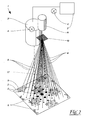
- the FIG. 1 shows a spatial representation of a device 1 for optically detecting an object 2, in particular a moving web 2.
- the device 1 has a camera 3, which is preferably designed as a CCD or CMOS camera. In principle, however, the subject of the invention is not limited to these kinds of cameras.
- the camera 3 detects the object 2 optically, wherein light sources 4 are indicated only symbolically.
- an optically scannable pattern 5 is provided, which is detected by the device 1.
- the device 1 is intended to measure the pattern 5 as accurately as possible, which basically requires a precise alignment of the camera 3 with respect to the object 2. However, this exact alignment is often not feasible in practice, as there is usually little time available. In particular, when running webs as object 2, there is the additional problem that either the entire system would have to stand still during the adjustment of the camera 3 or the functionality of the production plant is not completely guaranteed because of a maladjustment of the camera 3.
- the image which the camera 3 detects is changed in size.
- the image is distorted in perspective, which makes it impossible to accurately detect the pattern 5 provided on the object 2.
- the device 1 provides an additional reference by means of which the image distortions can be quantitatively detected.
- This reference is formed by four reference light sources 6 in the form of lasers 6, which are connected via a holder 7 fixed to the camera 3.
- the lasers 6 are adjusted in such a way that the reference light beams 8 emanating from them do not run parallel to one another.
- the reference light beams 8 rather diverge from an imaginary point above the camera 3.
- the divergence angle is determined by the orientation of the laser 6.
- the reference light beams 8 span the mantle edges of a pyramid.
- the reference light beams 8 hit the object 2 in four points of incidence 9.
- the wavelength of the reference light sources 6 is chosen such that it can be detected by the camera 3.
- the impact points 9 of the reference light beams 8 are therefore characterized in the camera image by an increased brightness. It is also intended to operate the reference light sources 6 not in continuous wave mode, but pulsed, wherein the pulse period is a multiple of the cycle time of the camera 3. In this way, certain images that the camera 3 generates are generated with and others without reference light beams 8. A simple difference between the two images thus results exclusively in the effect of the reference light beams, so that in this way the points of impingement 9 can be measured particularly accurately and reliably.
- the camera 3 is followed by an arithmetic circuit 3 ', which equalizes the recorded image.
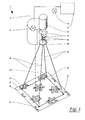
- FIG. 2 shows an alternative embodiment of the device 1 according to FIG. 1 , wherein like reference numerals designate like parts. In the following, only the differences from the embodiment according to FIG. 1 received.
- the device 1 according to FIG. 2 has only one reference light source 6 in the form of a laser 6. This also simplifies the holder 7, the in FIG. 2 has been omitted for simplicity.
- the laser 6 is followed by an optical grating 10 whose mesh size is in the range of a few microns.
- the cross-shaped representation of the grid 10 according to FIG. 2 serves only the basic illustration and differs considerably from a scale representation.
- the emittered by the laser 6 reference light beam 8 is diffracted, whereby a grid-shaped diffraction pattern is formed.
- the points of impingement 9 of the reference light beams 8 on the object 2 form a matrix in this case, with adjacent points of incidence 9 having substantially equal distances.
- This arrangement has over the embodiment according to FIG. 1 the significant advantage that only a single laser 6 is required to produce all the reference light beams 8.
- the location of the impact points 9 does not depend on an adjustment of the laser 6 from each other, this is exclusively due to the grid 10 used, which can be produced with high precision.
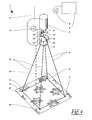
- FIG. 3 shows a further embodiment of the device 1 according to FIG. 2 , wherein like reference numerals designate like parts. In the following, only the differences from the embodiment according to FIG. 2 received.
- two birefringent crystals 11 are used in this case. Due to the oblique incidence, these birefringent crystals 11 cause an offset of the reference light beam 8. This offset occurs on the one hand in the X direction and on the other hand in the Y direction. so that a total of four reference light beams 8 are formed. It is important in this context, however, that the reference light source 6 emits unpolarized light to use the birefringence. If the reference light source 6 emits polarized light, it is expedient to set the polarization plane such that it is inclined at about 45 ° to the optical axis of the birefringent crystals 11.
- FIG. 4 shows a further embodiment of the device according to FIG. 3 , wherein like reference numerals again designate like parts. In the following, only the differences from the embodiment according to FIG. 3 received.
- the embodiment according to FIG. 4 instead of birefringent crystals 11, semipermeable mirrors 13, to which parallel aligned mirrors 14 are assigned, are used.
- the reference light beam 8 first strikes the upper semitransparent mirror 13, which transmits a part of the light and reflects a part.
- the reflected beam 15 then passes to a parallel to the semitransparent mirror 13 aligned mirror 14, the reflected beam 15 parallel to the original propagation direction of the reference light beam 8 deflects.
- Both beams 8, 15 then pass to the second semitransparent mirror 13, which transmits part of the light and in turn reflects a part.
- the two reflected beams 16 then pass to a mirror 14 oriented in parallel, which deflects the reflected beams 16 parallel to the original propagation direction of the reference light beam 8. In this way, four parallel reference light beams 8, which in turn are divergent aligned by the lens 12.
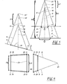
- FIG. 5 shows a front view of the device 1 according to FIG. 4 , except for the representation of the camera 3 and the reference light source 6 for the sake of simplicity of illustration.
- the divergent reference light beams 8 are incident on the object 2, so that the impact points 9 in the camera image will appear correspondingly brighter.
- the reference light beams 8 include a divergence angle 18. This divergence angle 18 is structurally predetermined and therefore constant. The distance 19 between the impingement points 9 is therefore directly proportional to the distance between the object 2 and a convergence point 21 of the reference light beams 8.
- the object 2 includes with the camera axis 17 is a non-rectangular inclination angle 22, which in particular from the in FIG. 6 is shown above elevation view.
- FIG. 6 an associated side elevation is shown on the right.
- the imaginary connecting lines 23 between the impingement points 9 shown in this figure run parallel to one another, since in this direction the object 2 is oriented perpendicular to the camera axis 17.
- connecting lines 24 in the direction which is basically normal in this case converge due to the inclination of the object 2.
- FIG. 6 centrally represented plan view corresponding perspective distortion. Because of this distortion, the points of impact 9 no longer lie on the vertices of a square, but on those of a trapezoid.
- the distance 20 of the object 2 from the camera 3 can in a similar way - as to FIG. 5 described - be calculated.
- the following expression must be calculated, the one in FIG. 6 with the dashed line 25 shown average value P m of the pixel number of the lengths 26, 27 contains.
- a K N G - P m ⁇ cot ⁇ cot 2 ⁇ - cot 2 ⁇ cot ⁇ cot 2 ⁇ - cot 2 ⁇ - K
- the inclination angle 22 of the object 2 can be calculated directly. For this, consider the plan view according to FIG. 6 which is received by the camera 3 in this form.
- the measured pixel values can also be used for the variables u , v .
- the rule described above is used for both coordinates.
- the inclination of the object 2 causes perspective distortion in both coordinate directions, so that the original square becomes an irregular square.
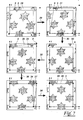
- FIG. 7 a method for equalizing the image 28 taken by the camera 3 using the impingement points 9 contained in the camera image 28.
- the correction process begins at the top left, where the original camera image 28 is shown.
- the impact points 9 form an irregular. Quadrilateral which is in no way aligned with the coordinate axes x, y.
- the entire image 28 is first subjected to translation and rotation 29.
- the lower left impingement point 9 is moved to the coordinate origin and the right lower impingement point 9 is rotated on the X axis.
- This operation is applied to the entire image data 28, so that both the recorded pattern 5 and the landing points 9 are transformed accordingly.
- the transformed image 31 is subjected to a parallelogram transformation, through which the upper left impingement point 9 comes to rest on the Y axis.
- the X-axis is unaffected by this transformation, so that the lower impact points 9 in their position remain. This transformation is also applied to the entire image data 31.
- the re-transformed image 33 is subjected to an expansion that affects both the X and Y axes. Due to this elongation 32, the upper left and lower right landing points 9 respectively reach normalized values of the Y or X axis. Now only the right upper impact point 9 is not in its correct position at the upper right corner of the normalized square 34th
- the retransformed image 35 is subjected to a trapezoidal transformation 36, wherein the trapezoidal axis passes through the upper left impingement point 9. In this way, all points on the X or Y axis remain untouched by the transformation. Through this trapezoidal transformation 36, the upper right landing point 9 reaches the correct Y value.
- the transformed image 37 is subjected to another trapezoidal transformation 38.
- the axis of the trapezoidal transformation 38 in this case runs through the lower right incidence point 9.
- This transformation 38 leaves the values on the X or Y axis unaffected. In this way, the right upper impact point 9 comes to lie in the upper right corner of the normalized square 34.
- This transformation 38 like all the above-mentioned transformations, is applied to all image data, so that the result is an equalized image 39, in which the impact points 9 form the vertices of the normalized square 34.
- the pattern 5 can be measured accurately.
- the rectified camera image 39 can also be used without problems for pattern-appropriate straightening, since distortions contained in these image data originate unambiguously from the textile web itself and not from alignment errors of the camera 3.
- the entire equalization can also be done in a single step.
- the pixels ( x , y ) of the original camera image 28 are subjected to the following transformation to produce the equalized pixels ( x ' , y ').
- x ' y ' a b + x y + c + gy f e d + hx
- the sought-after transformation parameters a to h are on the left-hand side, while the measured positions of the impact points 9 in the camera image 28 and the associated normalized positions are on the right-hand side.
- the normalized positions P ' result directly from the geometry of the reference light beams 8.
- the transformation parameters can be calculated directly from the measured positions of the points of impingement 9 in the camera image 28 without having to always transform the entire image data.
- the above-described transformation is once applied to the entire image data 28 so as to directly calculate the equalized image 39.
Landscapes
- Engineering & Computer Science (AREA)
- Physics & Mathematics (AREA)
- General Physics & Mathematics (AREA)
- Theoretical Computer Science (AREA)
- Multimedia (AREA)
- Life Sciences & Earth Sciences (AREA)
- Health & Medical Sciences (AREA)
- Chemical & Material Sciences (AREA)
- Analytical Chemistry (AREA)
- Biochemistry (AREA)
- General Health & Medical Sciences (AREA)
- Immunology (AREA)
- Pathology (AREA)
- Length Measuring Devices By Optical Means (AREA)
Priority Applications (1)
| Application Number | Priority Date | Filing Date | Title |
|---|---|---|---|
| EP07024244A EP2053348A1 (fr) | 2007-10-23 | 2007-12-13 | Procédé et dispositif destinés à la saisie optique d'objets |
Applications Claiming Priority (2)
| Application Number | Priority Date | Filing Date | Title |
|---|---|---|---|
| EP07020691 | 2007-10-23 | ||
| EP07024244A EP2053348A1 (fr) | 2007-10-23 | 2007-12-13 | Procédé et dispositif destinés à la saisie optique d'objets |
Publications (1)
| Publication Number | Publication Date |
|---|---|
| EP2053348A1 true EP2053348A1 (fr) | 2009-04-29 |
Family
ID=40342460
Family Applications (1)
| Application Number | Title | Priority Date | Filing Date |
|---|---|---|---|
| EP07024244A Withdrawn EP2053348A1 (fr) | 2007-10-23 | 2007-12-13 | Procédé et dispositif destinés à la saisie optique d'objets |
Country Status (1)
| Country | Link |
|---|---|
| EP (1) | EP2053348A1 (fr) |
Citations (4)
| Publication number | Priority date | Publication date | Assignee | Title |
|---|---|---|---|---|
| EP0157299A1 (fr) * | 1984-03-26 | 1985-10-09 | Hitachi, Ltd. | Appareil d'exploitation d'images |
| EP0974811A1 (fr) * | 1998-07-21 | 2000-01-26 | Hewlett-Packard Company | Caméras numériques |
| EP1431708A2 (fr) * | 2002-12-20 | 2004-06-23 | Delphi Technologies, Inc. | Caractérisation d'une surface d'un objet en utilisant la triangulation optique et une seule caméra |
| US20040128102A1 (en) * | 2001-02-23 | 2004-07-01 | John Petty | Apparatus and method for obtaining three-dimensional positional data from a two-dimensional captured image |
-
2007
- 2007-12-13 EP EP07024244A patent/EP2053348A1/fr not_active Withdrawn
Patent Citations (4)
| Publication number | Priority date | Publication date | Assignee | Title |
|---|---|---|---|---|
| EP0157299A1 (fr) * | 1984-03-26 | 1985-10-09 | Hitachi, Ltd. | Appareil d'exploitation d'images |
| EP0974811A1 (fr) * | 1998-07-21 | 2000-01-26 | Hewlett-Packard Company | Caméras numériques |
| US20040128102A1 (en) * | 2001-02-23 | 2004-07-01 | John Petty | Apparatus and method for obtaining three-dimensional positional data from a two-dimensional captured image |
| EP1431708A2 (fr) * | 2002-12-20 | 2004-06-23 | Delphi Technologies, Inc. | Caractérisation d'une surface d'un objet en utilisant la triangulation optique et une seule caméra |
Similar Documents
| Publication | Publication Date | Title |
|---|---|---|
| EP3003633B1 (fr) | Dispositif et procédé pour déterminer la position focale d'un faisceau d'énergie à haute densité | |
| DE102013008273B4 (de) | Dreidimensionale Bilderfassungsvorrichtung | |
| DE2256736C3 (de) | Meßanordnung zur automatischen Prüfung der Oberflächenbeschaffenheit und Ebenheit einer Werkstückoberfläche | |
| DE3715864C2 (de) | Verfahren und Vorrichtung zum Erfassen/Einstellen einer Verschiebung | |
| EP0502930B1 (fr) | Procede et dispositif de mesure optoelectronique d'objets | |
| DE3013498C2 (fr) | ||
| DE2802416A1 (de) | Optische vorrichtung | |
| DE102013213547A1 (de) | Kalibriereinrichtung und Kalibrierverfahren für eine Vorrichtung zum schichtweisen Herstellen eines Objekts | |
| DE102017205889B4 (de) | Optische Anordnung und Verfahren zur Laserinterferenzstrukturierung einer Probe | |
| DE102011012611A1 (de) | Verfahren und Vorrichtung zur berührungslosen Messung eines Winkels | |
| DE102017215976B4 (de) | Verfahren zur Vermessung eines Laserstrahls | |
| DE102018005903B4 (de) | Optisches System, optische Vorrichtung, Computerprogrammprodukt und Messverfahren | |
| EP3592499B1 (fr) | Procédé et dispositif de formation d'un rayonnement cohérent | |
| DE2653590A1 (de) | Vorrichtung zum ermitteln von fehlern in flaechenhaften mustern, insbesondere in photomasken | |
| EP4562378A1 (fr) | Ensemble de détection, ensemble de mesure et procédé de détermination de la position spatiale d'un faisceau laser | |
| DE4426107A1 (de) | Laser-Zeicheneinrichtung | |
| EP3953077B1 (fr) | Dispositif de mesure permettant de déterminer l'angle de pliage | |
| EP0128119B1 (fr) | Procédé et dispositif pour la mise au point de la distance d'un rayon lumineux sur un objet | |
| DE102011001475B4 (de) | Verfahren und Vorrichtungen zur Positionsbestimmung | |
| DE69105893T2 (de) | Vorrichtung zur Messung der Polarisation. | |
| EP2053348A1 (fr) | Procédé et dispositif destinés à la saisie optique d'objets | |
| EP2546599A1 (fr) | Système déflectométrique destiné à lýinspection de surfaces | |
| DE102007017649A1 (de) | Verfahren zum Bestimmen der Fokuslage von mindestens zwei Kanten von Strukturen auf einem Substrat | |
| DE102004020881B4 (de) | Verfahren und Vorrichtung zum geometrischen Kalibrieren von optoelektronischen Messbildkameras | |
| DE102016211310B3 (de) | Vorrichtung zur messung einer aberration, abbildungssysteme und verfahren zur messung einer aberration |
Legal Events
| Date | Code | Title | Description |
|---|---|---|---|
| PUAI | Public reference made under article 153(3) epc to a published international application that has entered the european phase |
Free format text: ORIGINAL CODE: 0009012 |
|
| AK | Designated contracting states |
Kind code of ref document: A1 Designated state(s): AT BE BG CH CY CZ DE DK EE ES FI FR GB GR HU IE IS IT LI LT LU LV MC MT NL PL PT RO SE SI SK TR |
|
| AX | Request for extension of the european patent |
Extension state: AL BA HR MK RS |
|
| AKX | Designation fees paid | ||
| STAA | Information on the status of an ep patent application or granted ep patent |
Free format text: STATUS: THE APPLICATION IS DEEMED TO BE WITHDRAWN |
|
| 18D | Application deemed to be withdrawn |
Effective date: 20091030 |
|
| REG | Reference to a national code |
Ref country code: DE Ref legal event code: 8566 |