EP2053388B1 - Biosensor-messsystem und messverfahren - Google Patents
Biosensor-messsystem und messverfahren Download PDFInfo
- Publication number
- EP2053388B1 EP2053388B1 EP07791365.5A EP07791365A EP2053388B1 EP 2053388 B1 EP2053388 B1 EP 2053388B1 EP 07791365 A EP07791365 A EP 07791365A EP 2053388 B1 EP2053388 B1 EP 2053388B1
- Authority
- EP
- European Patent Office
- Prior art keywords
- electrode
- measurement
- electrode system
- biosensor
- voltage
- Prior art date
- Legal status (The legal status is an assumption and is not a legal conclusion. Google has not performed a legal analysis and makes no representation as to the accuracy of the status listed.)
- Active
Links
Images


Classifications
-
- G—PHYSICS
- G01—MEASURING; TESTING
- G01N—INVESTIGATING OR ANALYSING MATERIALS BY DETERMINING THEIR CHEMICAL OR PHYSICAL PROPERTIES
- G01N27/00—Investigating or analysing materials by the use of electric, electrochemical, or magnetic means
- G01N27/26—Investigating or analysing materials by the use of electric, electrochemical, or magnetic means by investigating electrochemical variables; by using electrolysis or electrophoresis
-
- G—PHYSICS
- G01—MEASURING; TESTING
- G01N—INVESTIGATING OR ANALYSING MATERIALS BY DETERMINING THEIR CHEMICAL OR PHYSICAL PROPERTIES
- G01N27/00—Investigating or analysing materials by the use of electric, electrochemical, or magnetic means
- G01N27/26—Investigating or analysing materials by the use of electric, electrochemical, or magnetic means by investigating electrochemical variables; by using electrolysis or electrophoresis
- G01N27/28—Electrolytic cell components
- G01N27/30—Electrodes, e.g. test electrodes; Half-cells
- G01N27/327—Biochemical electrodes, e.g. electrical or mechanical details for in vitro measurements
- G01N27/3271—Amperometric enzyme electrodes for analytes in body fluids, e.g. glucose in blood
- G01N27/3274—Corrective measures, e.g. error detection, compensation for temperature or hematocrit, calibration
-
- G—PHYSICS
- G01—MEASURING; TESTING
- G01N—INVESTIGATING OR ANALYSING MATERIALS BY DETERMINING THEIR CHEMICAL OR PHYSICAL PROPERTIES
- G01N27/00—Investigating or analysing materials by the use of electric, electrochemical, or magnetic means
- G01N27/26—Investigating or analysing materials by the use of electric, electrochemical, or magnetic means by investigating electrochemical variables; by using electrolysis or electrophoresis
- G01N27/28—Electrolytic cell components
- G01N27/30—Electrodes, e.g. test electrodes; Half-cells
- G01N27/327—Biochemical electrodes, e.g. electrical or mechanical details for in vitro measurements
-
- G—PHYSICS
- G01—MEASURING; TESTING
- G01N—INVESTIGATING OR ANALYSING MATERIALS BY DETERMINING THEIR CHEMICAL OR PHYSICAL PROPERTIES
- G01N27/00—Investigating or analysing materials by the use of electric, electrochemical, or magnetic means
- G01N27/26—Investigating or analysing materials by the use of electric, electrochemical, or magnetic means by investigating electrochemical variables; by using electrolysis or electrophoresis
- G01N27/416—Systems
-
- G—PHYSICS
- G01—MEASURING; TESTING
- G01N—INVESTIGATING OR ANALYSING MATERIALS BY DETERMINING THEIR CHEMICAL OR PHYSICAL PROPERTIES
- G01N33/00—Investigating or analysing materials by specific methods not covered by groups G01N1/00 - G01N31/00
- G01N33/48—Biological material, e.g. blood, urine; Haemocytometers
Definitions
- the present invention relates to a biosensor measurement system and a measurement method and, more particularly, to those capable of detecting an impact due to such as falling of a biosensor.
- a biosensor in which a sample is introduced into a cavity from a front-end sample supply port by a surfactant layer applied to an upper surface in the cavity.
- a sensor electrode is composed of a working electrode and a counter electrode, and an oxidation-reduction current value between the counter electrode and the working electrode is measured to determine the quantity of a target substance.
- an enzyme sensor is configured such that a working electrode and a counter electrode are placed apart from each other with a predetermined interval and contacting a reduced electron carrier that is obtained by a specific reaction between the target substance and the enzyme, and a voltage is applied between the working electrode and the counter electrode for a predetermined period to oxidize the reduced electron carrier, and a current value (waveform) obtained at this time is measured to determine the quantity of the target substance.
- a biosensor measurement system 700 includes a biosensor 30 having a sample application part 30a at its front end, and a measurement device 10 which measures the concentration of a specific component in a liquid sample applied to the sample application part 30a.
- the measurement device 10 includes a support part 2 in which the biosensor 30 is inserted, and a display part 11 which displays the measurement result.
- Figure 8 shows an example of the biosensor 30, which is obtained by laminating a cover 31, a spacer 33, a reagent layer 35, and an insulating substrate 36.
- the cover 31 has a vent hole 32 in its center.
- the spacer 33 has an approximately rectangular sample supply channel 34.
- the reagent layer 35 supports a reagent which enzymatically reacts with the specific component in the liquid sample.
- the insulating substrate 36 comprises polyethylene terephthalate or the like, and an electrode layer is formed at its surface.
- the electrode layer is divided by laser or printing, thereby forming a working electrode 37, a detection electrode 38, and a counter electrode 39.
- a disordered waveform is caused by an external factor such as an impact due to falling of the sensor during measurement, or a procedure of sample application, or a deterioration of the sensor itself due to such as exposure, resulting in abnormal values.
- the reduced electron carrier substance which is obtained by a specific reaction between the target substance and the enzyme is oxidized by applying a voltage between the working electrode and the counter electrode for a predetermined period, and the obtained current value (waveform) is measured to determine the quantity of the target substance.
- the conventional self monitoring blood-glucose biosensor comprising the sensor and the measurement device is very small in size, it might be dropped due to faulty operation or the like.
- a disordered waveform (abnormal waveform) is caused by an external factor such as an impact due to falling of the sensor or a procedure of sample application during the measurement time, and thereby the measured value is significantly deviated from the true value.
- the present invention is made to solve the above-described problems and has for its object to provide a biosensor measurement system and a measurement method having high measurement precision, which can eliminate the measurement results that are obtained when an impact due to such as falling of the biosensor occurs, or under other abnormal conditions.
- a measurement method using a biosensor having a first electrode system for measuring a target substance, which comprises a working electrode and a counter electrode, and a reagent layer containing an oxidation-reduction enzyme for oxidizing or reducing the target substance, which is disposed in the vicinity of the first electrode system, the method including the steps of applying a voltage to the first electrode system after a liquid sample is introduced onto the first electrode system, detecting an oxidation-reduction current that is generated by the voltage application, and converting the current value into the quantity of the target component, wherein the biosensor has, in addition to the first electrode system, a second electrode system for abnormality detection which comprises a working electrode and a counter electrode, and a voltage is applied to the second electrode system during the target measurement period so as to detect an abnormal waveform current during the target measurement period.
- a voltage application pattern to the first electrode system has a halt period when no voltage is applied.
- a voltage is continuously applied to the second electrode system during the target measurement period.
- a constant voltage is continuously applied to the second electrode system during the measurement period.
- a predetermined threshold range is set when monitoring the current waveform of the second electrode system, and the monitored waveform is judged as an abnormal waveform when the waveform is outside the threshold range.
- the predetermined threshold range is set based on normal measurement response values, or it is set using differences of the response values between the respective measurement points.
- a biosensor measurement system having a measurement device and a biosensor including a first electrode system for measuring a target component, which comprises a working electrode and a counter electrode, and a reagent layer containing at least an oxidation-reduction enzyme for oxidizing or reducing a specific target component, which is disposed in the vicinity of the first electrode system, said measurement device being adapted to apply a voltage to the first electrode system after a liquid sample is introduced onto the first electrode system, to detect an oxidation-reduction current that is generated by the voltage application, and to convert the current value into the quantity of the target component to determine the quantity of the target component, wherein the biosensor further includes, in addition to the first electrode system, a second electrode system for abnormality detection which comprises a working electrode and a counter electrode, and said measurement device being adapted to supply a voltage to said second electrode system during the target measurement period so as to detect an abnormal current during the target measurement period.
- the second electrode system shares its counter electrode with the first electrode system.
- At least the working electrode of the second electrode system is disposed so as not to contact with the reagent layer.
- At least the working electrode of the second electrode system is placed at an upper position in the stream of introducing the liquid sample than the first electrode system.
- the electrodes constituting the second electrode system are also used as a sample detection electrode, a hematocrit correction electrode, or an interfering substance correction electrode other than the first electrode system.
- a biosensor measurement system which includes a target substance measurement electrode system comprising a working electrode and a counter electrode, and applies a voltage to the target substance measurement electrode system using a predetermined voltage application pattern to output an oxidation-reduction current measurement value obtained during the voltage application period, and the biosensor measurement system further includes, in addition to the target substance measurement electrode, an abnormal waveform detection electrode system for detecting an abnormal waveform, and detects an abnormal waveform using the abnormal waveform detection electrode system. Therefore, when an output of a normal measurement value cannot be expected in the following cases (1) to (4):
- a biosensor measurement system according to a first embodiment of the present invention, and a method for detecting an abnormal waveform in a biosensor.
- a blood glucose sensor which adopts blood as a sample to measure the glucose concentration in blood.
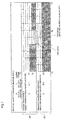
- Figure 1 is a diagram illustrating voltage application algorithms for a target substance measurement electrode and an abnormal waveform detection electrode in the biosensor measurement system of this first embodiment.
- abnormal waveform monitoring output shown in figure 1(b)
- a voltage of V3 is constantly applied to the abnormal waveform detection electrode to perform monitoring of abnormal waveforms
- abnormal waveform monitoring output is performed throughout the period from the voltage application start time T0 to the voltage application end time T3.
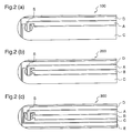
- Figure 2 is a diagram illustrating the configuration of the electrodes in the biosensor of this first embodiment.
- the fundamental configuration such as the arrangement of the cover, the spacer, the reagent, and the sample supply port is identical to that of the conventional biosensor.
- Figure 2(a) shows an electrode configuration in a first example 100 of the first embodiment, wherein A is a working electrode and C is a counter electrode. At least a reagent layer (not shown) for oxidizing or reducing a specific target component is disposed on these target substance measurement electrodes A and C.
- S shows the reagent layer placement position.
- D shows an abnormal waveform detection electrode. Since this abnormal waveform detection electrode D is disposed so as not to contact the reagent layer, only detection of an abnormal waveform can be carried out without affected by a reduced electron carrier substance which is caused by a reaction between the target substance and the reagent.
- the abnormal waveform detection electrode D is desirably disposed upstream the target substance measurement electrodes A and C, i.e., on the sample supply port (not shown) side which exists at the apex of the semicircular shape, in order to prevent the electrode D from being affected by the reduced electron carrier substance which is caused by the reaction between the target substance and the reagent.
- Figure 2(b) shows an electrode configuration of a second example 200 of the first embodiment, wherein A is a working electrode, B is a sample detection electrode, and C is a counter electrode.
- a reagent layer (not shown) is disposed on these target substance measurement electrodes A, B, and C.
- D is an abnormal waveform detection electrode. Since this abnormal waveform detection electrode D is disposed so as not to contact the reagent layer, only detection of an abnormal waveform can be carried out without affected by a reduced electron carrier substance which is caused by a reaction between the target substance and the reagent.
- the abnormal waveform detection electrode D is desirably disposed upstream the target substance measurement electrodes A, B, and C, i.e., on the sample supply port (not shown) side which exists at the apex of the semicircular shape, in order to prevent the electrode D from being affected by the reduced electron carrier substance which is caused by the reaction between the target substance and the reagent.
- the abnormal waveform detection electrode system may share its counter electrode with the target substance measurement electrode system.
- Figure 2(c) shows an electrode configuration of a third example 300 of the first embodiment, wherein A, B, C, and D are identical to those of the second example 200.
- a hematocrit correction electrode or an interfering substance correction electrode is provided as an electrode E.
- the abnormal waveform detection electrode may be implemented by the same electrode as the sample detection electrode, or the hematocrit correction electrode, or the interfering substance correction electrode other than the target substance measurement electrode. In this case, the biosensor can be easily configured.
- FIG. 3 is a diagram illustrating a detection flow in the biosensor abnormal waveform detection method of the first embodiment of the present invention.
- S1 is a step of judging whether the biosensor is set or not
- S2 is a step of judging whether introduction of blood is detected or not
- S3 is a step of starting measurement by the abnormal waveform detection electrode when the judgment result in the judgment step S2 is "Yes”
- S4 is a step of judging whether an abnormal waveform is detected or not
- S5 is a step of performing error display when the judgment result in the judgment step S4 is "Yes”
- S6 is a step of starting measurement of the target substance simultaneously with the measurement start step S3 by the abnormal waveform detection electrode when the judgment result in the judgment step S2 is "Yes”
- S7 is a step of calculating the concentration of the target substance after the step S6, and S8 is a step of displaying the concentration of the target substance.
- Figure 4 is a diagram illustrating the electrode configuration of the biosensor 200 (second example) and the block configuration of the measurement device 400 which are the constituents of the biosensor measurement system of the first embodiment.
- A, B, C, and D denote a working electrode, a sample detection electrode, a counter electrode, and an abnormal waveform detection electrode, respectively.
- C1, C2, C3, and C4 denote connectors
- SW denotes a switching circuit
- 40 denotes a reference voltage supply
- 41 denotes a current/voltage conversion circuit
- 42 denotes an A/D conversion circuit
- 43 denotes a CPU
- 44 denotes a display part comprising a liquid crystal display (LCD).
- LCD liquid crystal display
- the connectors C1, C2, C3, and C4 contact the working electrode A, the detection electrode B, the counter electrode C, and the abnormal waveform detection electrode D of the biosensor 200, respectively.
- the reference voltage supply 40 applies a voltage between the connectors C1, C2, C3, and C4.
- the switching circuit SW changes the connections between the connectors C1, C2, C3, C4, and the reference voltage supply 40, and the connections between the connectors C1, C2, C3, C4, and the current/voltage conversion circuit 41.
- the current/voltage conversion circuit 41 converts the currents flowing through the respective electrode systems into voltages.
- the A/D conversion circuit 42 converts the output values from the current/voltage conversion circuit 41 into pulses.
- the CPU 43 calculates the concentration of the specific component in the liquid sample, for example, the concentration of glucose, on the basis of the pulses outputted from the A/D conversion circuit 42.
- the display part 44 comprising an LCD or the like displays the calculation result obtained by the CPU 43 such as the glucose concentration.
- Example 1 ⁇ detection of abnormal waveform due to impact>
- Example 2 ⁇ detection of abnormal waveform due to exposed sensor>
- This experiment performs a comparison between the normal measurement and the abnormal measurement in which an impact is artificially given.
- the response value of the abnormal waveform detection electrode in the abnormal measurement deviates from the waveform obtained in the normal measurement at the point of 2.9sec. when an impact is given, and therefore, the abnormal waveform detection electrode detects the impact by the fingertip.
- a threshold range R is determined (normal measurement response value ⁇ 0.65 ⁇ A) based on the normal measurement response value which is obtained when using the abnormal waveform detection electrode of the present invention.
- the response value of the abnormal waveform detection electrode in the abnormal measurement is outside the set threshold range at the point of 2.9sec. when the impact is given, it can be judged as an abnormal waveform.
- the threshold range R can be set at the normal measurement ⁇ 10S.D. considering the standard deviation (S.D.) at the normal measurement, and thereby the abnormal waveform can be detected without falsely judging the normal measurement as the abnormal measurement (false judgment rate: 1.5 ⁇ 10 -21 %).
- the threshold range may be set at normal measurement ⁇ 6S.D. or ⁇ 3S.D. as needed.
- the abnormal value is eliminated by error display.
- While the respective measurement points are set at intervals of 0.1sec., intervals of about 0.05sec. are desirable for further enhancement of the detection precision. Further, in order to enhance the precision of the waveform obtained, it is desired to continuously apply a constant voltage to the abnormal waveform detection electrode during the measurement period.
- Figure 5 shows the measurement results of Example 1 ( ⁇ detection of abnormal waveform due to impact>) of the first embodiment, wherein figure 5(a) shows the measurement electrode current value and figure 5(b) shows the abnormal waveform detection electrode current value.
- the abscissa shows the measurement time while the ordinate shows the glucose measurement electrode current value ( ⁇ A), and ⁇ dots show the normal measurement while ⁇ dots show the abnormal measurement.
- the abscissa shows the measurement time while the ordinate shows the abnormal waveform detection electrode current value ( ⁇ A), ⁇ dots show the normal measurement while A dots show the abnormal measurement, broken lines show the upper threshold value Tu and the lower threshold value Tl, and a threshold range R is determined by the upper threshold value Tu and the lower threshold value Tl.
- Example 1 ⁇ detection of abnormal waveform due to impact>
- the curve of the waveform shown by ⁇ marks is smooth in the glucose measurement electrode current waveform shown in figure 5(a) , that is, the transition of the current value during the abnormal measurement shown by ⁇ marks is smooth. Therefore, it is not possible to immediately judge that an impact such as falling of the sensor occurred, by seeing the curve of the waveform of ⁇ marks.
- the measured current value of the waveform of ⁇ marks obtained when the voltage application is ended significantly deviates from the current value obtained by the normal measurement of the sensor shown by ⁇ marks, but it is not desirable to recognize the measured current value of ⁇ marks as the measured current value in the normal state.
- the current value of the abnormal waveform detection electrode (the current value shown by A marks) shown in figure 5(b) jumps from 1.32 ⁇ A to 3.05 ⁇ A at the point around 2.9sec., and it is possible to judge by this "jumping" in the waveform that, also in figure 5(a) , there was an abnormality due to an impact at the point around 2.9sec. in the period from T1(2sec) to T2(3sec) where no output is detected.
- This experiment performs measurements of the exposed sensor and the normal sensor.
- the response value of the glucose measurement electrode in the exposed sensor is increased due to the deterioration of the sensor, and the response value deviates from that obtained by the normal sensor to display an abnormal value.
- the response value deviates from that of the normal sensor because the condition of the reagent is changed due to the exposure.
- a threshold value is set (normal measurement response value ⁇ 0.65 ⁇ A) based on the response value of the abnormal waveform detection electrode of the normal sensor.
- the response value of the abnormal waveform detection electrode obtained during the exposed sensor measurement is outside the threshold range, it can be judged as an abnormal waveform.
- the abnormal waveform When the abnormal waveform is detected by the abnormal waveform detection electrode, the abnormal value is eliminated by error display.
- Figure 6 shows the measurement result of Example 2 ( ⁇ detection of abnormal waveform due to exposed sensor>) of the first embodiment, wherein figure 6(a) shows the measurement electrode current value and figure 6(b) shows the abnormal waveform detection electrode current value.
- the abscissa shows the measurement time while the ordinate shows the glucose measurement electrode current value ( ⁇ A), and ⁇ dots show the normal sensor while ⁇ dots show the exposed sensor.
- the abscissa shows the measurement time while the ordinate shows the abnormal waveform detection electrode current value ( ⁇ A), ⁇ dots show the normal sensor while ⁇ dots show the exposed sensor, broken lines show the upper threshold value Tu and the lower threshold value Tl, and a threshold range R is determined by the upper threshold value Tu and the lower threshold value Tl.
- Example 2 ( ⁇ detection of abnormal waveform due to exposed sensor>)
- the results shown in figures 6(a) and 6(b) are obtained by performing measurements of the exposed sensor and the normal sensor, and the followings are found.
- the response value of the glucose measurement electrode of the exposed sensor is increased due to the deterioration of the sensor, and thereby the response value deviates from the response value of the glucose measurement electrode of the normal sensor to show the abnormal value.
- the response value deviates from that of the normal sensor because the condition of the reagent is changed due to the exposure.
- a threshold range to, for example, ⁇ 0.65 ⁇ A of the response value of the normal measurement on the basis of the response value of the abnormal waveform detection electrode of the normal sensor
- the response value of the abnormal waveform detection electrode obtained in the exposed sensor measurement can be judged as an abnormal waveform if the response value exceeds this threshold range, and thereby the sensor can be judged as an exposed sensor.
- the abnormal waveform detection electrode since the abnormal waveform detection electrode is newly provided in addition to the electrodes for target substance quantitation, when an impact due to such as falling of the sensor occurs in the halt period where no voltage is applied in the voltage application algorithm, the abnormal waveform detection electrode can detect this impact, and furthermore, even an exposed sensor can be detected by the abnormal waveform which is detected by the abnormal waveform detection electrode.
- the measurement target substance is not restricted to blood glucose, and it may be a biological sample such as cholesterol, triglyceride, lactic acid, uric acid, bilirubin, or alcohol, an ambient sample, or a food sample may be adopted with the same effects as described above.
- a self monitoring blood-glucose biosensor having high measurement precision can be obtained at reduced cost, and it is useful in hospitals, homes, and the like.
Landscapes
- Health & Medical Sciences (AREA)
- Life Sciences & Earth Sciences (AREA)
- Chemical & Material Sciences (AREA)
- Immunology (AREA)
- Molecular Biology (AREA)
- Pathology (AREA)
- Physics & Mathematics (AREA)
- Analytical Chemistry (AREA)
- Biochemistry (AREA)
- General Health & Medical Sciences (AREA)
- General Physics & Mathematics (AREA)
- Hematology (AREA)
- Chemical Kinetics & Catalysis (AREA)
- Electrochemistry (AREA)
- Engineering & Computer Science (AREA)
- Biomedical Technology (AREA)
- Urology & Nephrology (AREA)
- Food Science & Technology (AREA)
- Medicinal Chemistry (AREA)
- Investigating Or Analysing Biological Materials (AREA)
- Measuring Or Testing Involving Enzymes Or Micro-Organisms (AREA)
- Investigating Or Analyzing Materials By The Use Of Electric Means (AREA)
- Apparatus Associated With Microorganisms And Enzymes (AREA)
Claims (12)
- Messverfahren, das einen Biosensor (100, 200, 300) benutzt, aufweisend ein erstes Elektrodensystem zum Messen einer Zielsubstanz, das eine Arbeitselektrode (A) und eine Gegenelektrode (C) umfasst, und eine ein Oxidations-Reduktions-Enzym zum Oxidieren oder Reduzieren der Zielsubstanz umfassende Reagensschicht, welche in der Nähe des ersten Elektrodensystems angeordnet ist, wobei das Verfahren die Schritte (S6, S7) des Beaufschlagens des ersten Elektrodensystems mit einer Spannung nach Aufbringen einer flüssigen Probe auf dem ersten Elektrodensystem, des Erkennens eines oxidationsreduzierenden Stroms, der durch die Spannungsbeaufschlagung erzeugt wird und des Umwandelns des Stromwertes in die Menge der Zielkomponente umfasst, wobei
der Biosensor, zusätzlich zu dem ersten Elektrodensystem, ein zweites Elektrodensystem zur Erkennung von Anomalitäten aufweist, das eine Arbeitselektrode und eine Gegenelektrode umfasst, und wobei am zweiten Elektrodensystem während der Zielmessperiode eine Spannung angelegt wird, um während der Zielmessperiode einen Strom von unnormaler Wellenform (S3) zu erkennen. - Messverfahren nach Anspruch 1, wobei
ein Spannungsbeaufschlagungsmuster für das erste Elektrodensystem eine Unterbrechungsperiode, wenn keine Spannung angelegt ist, aufweist. - Messverfahren nach Anspruch 1 oder 2, wobei
eine Spannung während der Zielmessperiode kontinuierlich am zweiten Elektrodensystem angelegt ist. - Messverfahren nach einem der Ansprüche 1 bis 3, wobei
während der Zielmessperiode eine konstante Spannung kontinuierlich am zweiten Elektrodensystem angelegt ist. - Messverfahren nach einem der Ansprüche 1 bis 4, wobei
die Stromwellenform des zweiten Elektrodensystems zur Erkennung einer unnormalen Wellenform überwacht wird. - Messverfahren nach Anspruch 5, wobei
bei der Überwachung der Stromwellenform des zweiten Elektrodensystems ein im Voraus bestimmter Schwellenwertbereich (R) festgelegt ist und die überwachte Wellenform als eine unnormale Wellenform beurteilt wird, wenn die Wellenform außerhalb des Schwellenwertbereichs liegt. - Messverfahren nach Anspruch 7, wobei
der im Voraus bestimmte Schwellenwertbereich (R) auf Basis normaler Messreaktionswerte oder unter Anwenden der Unterschiede der Reaktionswerte zwischen den jeweiligen Messpunkten festgelegt ist. - Biosensor-Messsystem, aufweisend eine Messvorrichtung (400) und einen Biosensor (100, 200, 300), der ein erstes Elektrodensystem zum Messen einer Zielsubstanz umfasst, das eine Arbeitselektrode (A) und eine Gegenelektrode (C) aufweist und eine ein Oxidations-Reduktions-Enzym zum Oxidieren oder Reduzieren einer spezifischen Zielkomponente umfassende Reagensschicht, welche in der Nähe des ersten Elektrodensystems angeordnet ist, wobei die Messvorrichtung (400) angepasst ist zum Anlegen einer Spannung am ersten Elektrodensystem nach Aufbringen einer flüssigen Probe zum Erkennen eines oxidationsreduzierenden Stroms, der durch die Spannungsbeaufschlagung erzeugt wird, und zum Umwandeln des Stromwertes in die Menge der Zielkomponente zum Bestimmen der Menge der Zielkomponente,
wobei der Biosensor, zusätzlich zum ersten Elektrodensystem, ein zweites Elektrodensystem zur Erkennung von Anomalitäten ferner aufweist, das eine Arbeitselektrode und eine Gegenelektrode umfasst, und wobei die Messvorrichtung (400) angepasst ist zur Spannungsversorgung des zweiten Elektrodensystems während der Zielmessperiode, um während der Zielmessperiode einen unnormalen Strom zu erkennen. - Biosensor-Messsystem nach Anspruch 8, wobei
das zweite Elektrodensystem die Gegenelektrode (C) mit dem ersten Elektrodensystem teilt. - Biosensor-Messsystem nach Anspruch 8 oder 9, wobei
wenigstens die Arbeitselektrode (A) des zweiten Elektrodensystems so angeordnet ist, dass sie nicht mit der Reagensschicht in Berührung kommt. - Biosensor-Messsystem nach einem der Ansprüche 8 bis 10, wobei
wenigstens die Arbeitselektrode (C) des zweiten Elektrodensystems in einer höheren Position im Strom der Einführung der flüssigen Probe angeordnet ist als das erste Elektrodensystem. - Biosensor-Messsystem nach einem der Ansprüche 8 bis 11, wobei
die das zweite Elektrodensystem bildenden Elektroden außerdem angepasst sind für eine Anwendung als Probenerkennungselektrode, als Hämatokrit-Korrekturelektrode, als Störsubstanz-Korrekturelektrode oder ein anderes als das erste Elektrodensystem verwendet werden.
Applications Claiming Priority (2)
| Application Number | Priority Date | Filing Date | Title |
|---|---|---|---|
| JP2006203833 | 2006-07-26 | ||
| PCT/JP2007/064665 WO2008013224A1 (en) | 2006-07-26 | 2007-07-26 | Biosensor measuring system, and measuring method |
Publications (3)
| Publication Number | Publication Date |
|---|---|
| EP2053388A1 EP2053388A1 (de) | 2009-04-29 |
| EP2053388A4 EP2053388A4 (de) | 2013-12-25 |
| EP2053388B1 true EP2053388B1 (de) | 2016-08-31 |
Family
ID=38981535
Family Applications (1)
| Application Number | Title | Priority Date | Filing Date |
|---|---|---|---|
| EP07791365.5A Active EP2053388B1 (de) | 2006-07-26 | 2007-07-26 | Biosensor-messsystem und messverfahren |
Country Status (7)
| Country | Link |
|---|---|
| US (1) | US8945369B2 (de) |
| EP (1) | EP2053388B1 (de) |
| JP (1) | JP5239860B2 (de) |
| KR (1) | KR101096898B1 (de) |
| CN (1) | CN101495856B (de) |
| CA (1) | CA2658919C (de) |
| WO (1) | WO2008013224A1 (de) |
Families Citing this family (11)
| Publication number | Priority date | Publication date | Assignee | Title |
|---|---|---|---|---|
| CN103392127B (zh) | 2011-05-10 | 2016-05-04 | 松下健康医疗控股株式会社 | 生物体样本测定装置和使用其的生物体样本测定方法 |
| KR101367262B1 (ko) * | 2011-11-11 | 2014-02-26 | 주식회사 아이센스 | 자가혈당측정기 및 이를 이용한 측정 이상 감지 방법 |
| WO2013073073A1 (ja) * | 2011-11-18 | 2013-05-23 | 株式会社村田製作所 | バイオセンサおよびバイオセンサの製造方法 |
| JP5783891B2 (ja) * | 2011-12-12 | 2015-09-24 | グンゼ株式会社 | 計測表示装置 |
| JP6220170B2 (ja) | 2012-07-12 | 2017-10-25 | パナソニックヘルスケアホールディングス株式会社 | 液体試料測定装置 |
| CN103149244A (zh) * | 2013-01-11 | 2013-06-12 | 西北农林科技大学 | 一种便携式多指标阻抗生物传感器装置 |
| JP6404681B2 (ja) * | 2013-11-08 | 2018-10-10 | アークレイ株式会社 | 測定装置、及び測定方法 |
| JP6635789B2 (ja) * | 2013-11-27 | 2020-01-29 | Phcホールディングス株式会社 | 血液成分量の測定方法 |
| GB201511299D0 (en) * | 2015-06-26 | 2015-08-12 | Inside Biometrics Ltd | Test device and method of using a test device |
| US10746687B2 (en) | 2015-12-07 | 2020-08-18 | Arkray, Inc. | Method for measuring target component and apparatus for measuring target component |
| JP7781299B2 (ja) * | 2021-10-18 | 2025-12-05 | アグリトーク テクノロジー インコーポレイテッド | 生物検査用のチップベースの試薬ボックス及びその検測方法 |
Family Cites Families (19)
| Publication number | Priority date | Publication date | Assignee | Title |
|---|---|---|---|---|
| GB8332767D0 (en) | 1983-12-08 | 1984-01-18 | Lucas Ind Plc | Vehicle with load conscious brake pressure reducing valve |
| JP3011981B2 (ja) * | 1990-09-13 | 2000-02-21 | 新日本無線株式会社 | 複数基質濃度センサ |
| US5264103A (en) * | 1991-10-18 | 1993-11-23 | Matsushita Electric Industrial Co., Ltd. | Biosensor and a method for measuring a concentration of a substrate in a sample |
| US5352351A (en) | 1993-06-08 | 1994-10-04 | Boehringer Mannheim Corporation | Biosensing meter with fail/safe procedures to prevent erroneous indications |
| US5620579A (en) | 1995-05-05 | 1997-04-15 | Bayer Corporation | Apparatus for reduction of bias in amperometric sensors |
| JP3510461B2 (ja) | 1997-09-30 | 2004-03-29 | セラセンス インコーポレーテッド | バイオセンサデバイス |
| US6071391A (en) * | 1997-09-12 | 2000-06-06 | Nok Corporation | Enzyme electrode structure |
| US6576117B1 (en) * | 1998-05-20 | 2003-06-10 | Arkray | Method and apparatus for electrochemical measurement using statistical technique |
| JP2001183330A (ja) * | 1999-12-27 | 2001-07-06 | Matsushita Electric Ind Co Ltd | バイオセンサ |
| JP2002174641A (ja) | 2000-12-05 | 2002-06-21 | Ubukata Industries Co Ltd | 落下検出機構 |
| AU784254B2 (en) | 2001-05-21 | 2006-03-02 | Bayer Corporation | Improved electrochemical sensor |
| EP1452854B1 (de) * | 2001-11-20 | 2015-02-25 | ARKRAY, Inc. | Fehlerbeurteilungsverfahren zur analyse und analysegerät |
| WO2003044513A1 (en) * | 2001-11-20 | 2003-05-30 | Arkray, Inc. | Fail judging method and analyzer |
| JP2003270197A (ja) | 2002-03-12 | 2003-09-25 | Matsushita Electric Ind Co Ltd | バイオセンサ |
| US7132041B2 (en) * | 2003-02-11 | 2006-11-07 | Bayer Healthcare Llc | Methods of determining the concentration of an analyte in a fluid test sample |
| EP1642125B1 (de) | 2003-06-20 | 2017-09-27 | Roche Diabetes Care GmbH | Biosensor mit mehreren elektrischen funktionalitäten |
| EP3273232A2 (de) * | 2003-12-04 | 2018-01-24 | Panasonic Healthcare Holdings Co., Ltd. | Verfahren zur messung einer blutkomponente, sensor zur verwendung in dem verfahren und messgerät |
| US8357273B2 (en) | 2004-04-12 | 2013-01-22 | Arkray, Inc. | Analyzer |
| US8882987B2 (en) * | 2006-07-26 | 2014-11-11 | Panasonic Healthcare Co., Ltd. | Biosensor measurement system and method for detecting abnormal waveform in biosensor |
-
2007
- 2007-07-26 EP EP07791365.5A patent/EP2053388B1/de active Active
- 2007-07-26 WO PCT/JP2007/064665 patent/WO2008013224A1/ja not_active Ceased
- 2007-07-26 JP JP2008526802A patent/JP5239860B2/ja active Active
- 2007-07-26 US US12/375,111 patent/US8945369B2/en active Active
- 2007-07-26 CN CN2007800279906A patent/CN101495856B/zh active Active
- 2007-07-26 CA CA2658919A patent/CA2658919C/en active Active
- 2007-07-26 KR KR1020097003895A patent/KR101096898B1/ko active Active
Also Published As
| Publication number | Publication date |
|---|---|
| JPWO2008013224A1 (ja) | 2009-12-17 |
| CA2658919A1 (en) | 2008-01-31 |
| US20100000880A1 (en) | 2010-01-07 |
| KR101096898B1 (ko) | 2011-12-22 |
| EP2053388A4 (de) | 2013-12-25 |
| KR20090037483A (ko) | 2009-04-15 |
| WO2008013224A1 (en) | 2008-01-31 |
| US8945369B2 (en) | 2015-02-03 |
| EP2053388A1 (de) | 2009-04-29 |
| CN101495856B (zh) | 2013-06-05 |
| CN101495856A (zh) | 2009-07-29 |
| JP5239860B2 (ja) | 2013-07-17 |
| CA2658919C (en) | 2018-01-02 |
Similar Documents
| Publication | Publication Date | Title |
|---|---|---|
| US8945369B2 (en) | Biosensor measurement system and measurement method | |
| US7771583B2 (en) | Electrochemical determination of analytes | |
| AU2006233772B2 (en) | Analyte determination method and analyte meter | |
| US8882987B2 (en) | Biosensor measurement system and method for detecting abnormal waveform in biosensor | |
| AU2008279274B2 (en) | Electrochemical test strip | |
| EP2579031B1 (de) | Biosensor zur Messung einer Blutkomponente und von Hämatocrit | |
| TWI453401B (zh) | 使用時間解析電流測定法之用於分析物濃度測定的系統及方法(一) | |
| KR101102265B1 (ko) | 샘플에서 어날라이트를 측정하기 위한 시스템 및 방법 | |
| RU2594513C1 (ru) | Система и способ для обнаружения использованных и высохших датчиков | |
| EP2284526B1 (de) | Biosensorsystem und verfahren zur messung einer analytkonzentration in einer blutprobe | |
| US20100327886A1 (en) | Measurement device, measurement system, and concentration measurement method | |
| CA2639776A1 (en) | Systems and methods which discriminate between blood and non-blood samples, based on interferent current transients | |
| CN107250792A (zh) | 具有干扰校正的葡萄糖测试条 | |
| EP2916126B1 (de) | Analytisches werkzeug zur detektion eines probenbereitstellungszustands | |
| US20110036729A1 (en) | Control liquid judging method and analysis device | |
| US20100264942A1 (en) | Control Liquid Identifying Method and Analysis Device | |
| US20150276650A1 (en) | Method for fast measurement of specimen concentration | |
| AU2015258265B2 (en) | Analyte determination method and analyte meter | |
| KR20190038426A (ko) | 전기화학 바이오센서 에러 판별 장치 및 방법 | |
| HK1241462A1 (en) | Glucose test strip with interference correction | |
| AU2011205161A1 (en) | Analyte determination method and analyte meter |
Legal Events
| Date | Code | Title | Description |
|---|---|---|---|
| PUAI | Public reference made under article 153(3) epc to a published international application that has entered the european phase |
Free format text: ORIGINAL CODE: 0009012 |
|
| 17P | Request for examination filed |
Effective date: 20090224 |
|
| AK | Designated contracting states |
Kind code of ref document: A1 Designated state(s): AT BE BG CH CY CZ DE DK EE ES FI FR GB GR HU IE IS IT LI LT LU LV MC MT NL PL PT RO SE SI SK TR |
|
| AX | Request for extension of the european patent |
Extension state: AL BA HR MK RS |
|
| RBV | Designated contracting states (corrected) |
Designated state(s): DE ES FR GB IT PL |
|
| DAX | Request for extension of the european patent (deleted) | ||
| A4 | Supplementary search report drawn up and despatched |
Effective date: 20131126 |
|
| RIC1 | Information provided on ipc code assigned before grant |
Ipc: G01N 27/26 20060101AFI20131120BHEP Ipc: G01N 27/327 20060101ALI20131120BHEP Ipc: G01N 27/416 20060101ALI20131120BHEP |
|
| RAP1 | Party data changed (applicant data changed or rights of an application transferred) |
Owner name: PANASONIC HEALTHCARE CO., LTD. |
|
| RAP1 | Party data changed (applicant data changed or rights of an application transferred) |
Owner name: PANASONIC HEALTHCARE HOLDINGS CO., LTD. |
|
| REG | Reference to a national code |
Ref country code: DE Ref legal event code: R079 Ref document number: 602007047738 Country of ref document: DE Free format text: PREVIOUS MAIN CLASS: G01N0027260000 Ipc: G01N0027327000 |
|
| GRAP | Despatch of communication of intention to grant a patent |
Free format text: ORIGINAL CODE: EPIDOSNIGR1 |
|
| RIC1 | Information provided on ipc code assigned before grant |
Ipc: G01N 27/327 20060101AFI20151210BHEP |
|
| INTG | Intention to grant announced |
Effective date: 20160114 |
|
| GRAS | Grant fee paid |
Free format text: ORIGINAL CODE: EPIDOSNIGR3 |
|
| GRAA | (expected) grant |
Free format text: ORIGINAL CODE: 0009210 |
|
| AK | Designated contracting states |
Kind code of ref document: B1 Designated state(s): DE ES FR GB IT PL |
|
| REG | Reference to a national code |
Ref country code: GB Ref legal event code: FG4D |
|
| REG | Reference to a national code |
Ref country code: DE Ref legal event code: R096 Ref document number: 602007047738 Country of ref document: DE |
|
| PG25 | Lapsed in a contracting state [announced via postgrant information from national office to epo] |
Ref country code: ES Free format text: LAPSE BECAUSE OF FAILURE TO SUBMIT A TRANSLATION OF THE DESCRIPTION OR TO PAY THE FEE WITHIN THE PRESCRIBED TIME-LIMIT Effective date: 20160831 |
|
| PG25 | Lapsed in a contracting state [announced via postgrant information from national office to epo] |
Ref country code: PL Free format text: LAPSE BECAUSE OF FAILURE TO SUBMIT A TRANSLATION OF THE DESCRIPTION OR TO PAY THE FEE WITHIN THE PRESCRIBED TIME-LIMIT Effective date: 20160831 |
|
| REG | Reference to a national code |
Ref country code: DE Ref legal event code: R097 Ref document number: 602007047738 Country of ref document: DE |
|
| PLBE | No opposition filed within time limit |
Free format text: ORIGINAL CODE: 0009261 |
|
| STAA | Information on the status of an ep patent application or granted ep patent |
Free format text: STATUS: NO OPPOSITION FILED WITHIN TIME LIMIT |
|
| REG | Reference to a national code |
Ref country code: FR Ref legal event code: PLFP Year of fee payment: 11 |
|
| 26N | No opposition filed |
Effective date: 20170601 |
|
| REG | Reference to a national code |
Ref country code: FR Ref legal event code: PLFP Year of fee payment: 12 |
|
| REG | Reference to a national code |
Ref country code: DE Ref legal event code: R082 Ref document number: 602007047738 Country of ref document: DE Representative=s name: NOVAGRAAF BREVETS, FR Ref country code: DE Ref legal event code: R081 Ref document number: 602007047738 Country of ref document: DE Owner name: PHC HOLDINGS CORP., JP Free format text: FORMER OWNER: PANASONIC HEALTHCARE HOLDINGS CO., LTD., TOKYO, JP |
|
| PGFP | Annual fee paid to national office [announced via postgrant information from national office to epo] |
Ref country code: DE Payment date: 20250729 Year of fee payment: 19 |
|
| PGFP | Annual fee paid to national office [announced via postgrant information from national office to epo] |
Ref country code: IT Payment date: 20250721 Year of fee payment: 19 |
|
| PGFP | Annual fee paid to national office [announced via postgrant information from national office to epo] |
Ref country code: GB Payment date: 20250728 Year of fee payment: 19 |
|
| PGFP | Annual fee paid to national office [announced via postgrant information from national office to epo] |
Ref country code: FR Payment date: 20250728 Year of fee payment: 19 |