EP2053538A1 - Protection d'une zone de surveillance et support visuel d'un usinage automatisé - Google Patents
Protection d'une zone de surveillance et support visuel d'un usinage automatisé Download PDFInfo
- Publication number
- EP2053538A1 EP2053538A1 EP07119239A EP07119239A EP2053538A1 EP 2053538 A1 EP2053538 A1 EP 2053538A1 EP 07119239 A EP07119239 A EP 07119239A EP 07119239 A EP07119239 A EP 07119239A EP 2053538 A1 EP2053538 A1 EP 2053538A1
- Authority
- EP
- European Patent Office
- Prior art keywords
- areas
- automation
- evaluation
- security
- evaluations
- Prior art date
- Legal status (The legal status is an assumption and is not a legal conclusion. Google has not performed a legal analysis and makes no representation as to the accuracy of the status listed.)
- Granted
Links
Images

Classifications
-
- G—PHYSICS
- G06—COMPUTING OR CALCULATING; COUNTING
- G06V—IMAGE OR VIDEO RECOGNITION OR UNDERSTANDING
- G06V20/00—Scenes; Scene-specific elements
- G06V20/60—Type of objects
- G06V20/64—Three-dimensional [3D] objects
Definitions
- the invention relates to an optoelectronic device having at least one optoelectronic sensor for detecting spatially resolved information according to the preamble of claim 1 and to a corresponding method for securing a monitoring area and for visually supporting automated processing according to the preamble of claim 15.
- camera-based protective devices can be used for the surveillance of danger spots, especially of dangerous machines.
- a very customizable and accurate monitoring is possible with three-dimensional image data.
- various methods are known, for example stereoscopy, light transit time method, active triangulation, the evaluation of disturbances of passive two-dimensional patterns or distortions of actively projected patterns.
- the aim of such monitoring is to identify a condition that is to be classified as critical and then to secure the source of danger.
- a three-dimensional image sensor is installed above a hazardous machine, and virtual walls are configured to be monitored for improper object interventions.
- a 3D image sensor has a pyramid-shaped field of view, within which already due to the perspective of the establishment of the necessary protective fields because of their high complexity requires time and expertise. This configuration effort is often not sufficient profit compared to comparing with classical hedges, such as light curtains.
- an optoelectronic device according to claim 1 and a method for securing a surveillance area and for visual support of automated processing according to claim 15.
- the invention is based on the principle of separating the evaluations for safety tasks and automation tasks from each other by providing each separate zones. Problems that could result from overly complex evaluations when the two tasks are mixed are therefore avoided from the outset.
- the solution according to the invention is also scalable and modularly expandable by retrofitting additional sensors and corresponding computing capacities. Due to the separation of security and automation in such an extension, there are no interdependencies that could lead to a completely new implementation without such a separation in a combined evaluation.
- the sensor is advantageously a pixel-resolved line or matrix-shaped image sensor, in particular a visual 3D sensor according to the principle of stereoscopy, active triangulation or the light transit time.
- distance-resolving light grids are straight Image evaluation algorithms affected by the conflict, on the one hand to work absolutely error-free, not to endanger operating personnel by failure of the protection function, and on the other hand to guarantee high availability especially by fast-working and on possible low-cost hardware implementable algorithms.
- the separation into protection areas and automation areas has a particularly advantageous effect.
- the evaluation unit is preferably designed to evaluate the safety areas in safety evaluation cycles and the automation areas in the same or independent automation evaluation cycles, the safety areas and the automation areas being defined identically in each evaluation cycle.
- the security areas and the automation areas are fixed by the configuration. This simplifies the setup and simplifies the evaluation.
- the evaluation unit is designed to evaluate the safety areas in safety evaluation cycles and the automation areas in the same or independent automation evaluation cycles, the safety areas and the automation areas are defined dynamically over the evaluation cycles, in particular movements of a hazard, a vehicle or a robot to follow or adapt.
- both the protective fields and the areas to be monitored for automation can be carried dynamically and thus be used for a more flexible and accurate evaluation.
- the device advantageously has an interface for receiving further information about the monitoring area, in particular to a displacement sensor, speedometers, a plant, a vehicle or a robot controller. This completes the internal data of the sensor externally to allow a more accurate or simplified evaluation.
- the evaluation unit is preferably designed to define the safety areas, automation areas and open areas to which no evaluation takes place, overlapping-free and filling the entire monitoring area. Since the areas are overlap-free, conflicts in the various evaluations are consistently avoided.
- the configuration of free areas can serve the overview and facilitate evaluations, because in any case no algorithm is to be applied to the free areas.
- the evaluation unit is preferably designed to evaluate safety areas and / or automation areas in parallel, in particular by the device having at least one evaluation element for safety evaluations and at least one evaluation element for automation evaluations. Since, according to the invention, each area is assigned its own meaning, namely a protection or an automation task, the evaluations for acceleration and use of respectively cheaper evaluation modules can take place side by side.
- an evaluation element is any logic device, such as a microprocessor, a DSP, an FPGA, ASIC or more in question.
- the senor has an ROI unit (region of interest) in which definitions of the security areas and / or the automation areas can be stored as areas of interest, parallel to the security areas and / or the automation areas / or record differently, forward and / or evaluate.
- ROI unit region of interest
- This systematically advances the idea of parallelization and already ensures separation into the desired evaluation paths at the image sensor.
- an accelerated and simplified evaluation can be made.
- a warning and security device which can issue a warning or secure the source of danger upon detection of the evaluation unit of an inadmissible object intervention in a security area.
- an inadmissible object intervention in a protected area to prevent injury to operators graded first to a warning and, if an object intervention continues, Switch off the hazardous machinery or otherwise eliminate the source of danger.
- the device is designed to be safe in components and evaluations dealing with safety tasks, in particular by two-channel design, self-tests in cycles below the required response time, diversitively redundant components and evaluations or self-checking algorithms. This prevents hazards due to failures, as is often required in safety engineering, both on the safety-related hardware paths and on the corresponding software paths.
- a display device is provided in order to identify or visualize the security areas, the automation areas and / or the free areas, and on the other hand, a configuration device is provided for defining or changing the security areas, the automation areas and / or the free areas.
- a first optoelectronic sensor for the detection of information of the security areas and a second optoelectronic sensor for the detection of the automation areas is provided, wherein in particular the temporal and / or spatial resolution of the first and second optoelectronic sensor is different.
- both sensors can be aligned with those areas and those recording parameters that require their evaluations.
- the optoelectronic sensor is designed both for the detection of the information of the security areas as the automation areas, and the sensor can pass information from security areas with different temporal and / or spatial resolution to the evaluation unit as information from automation areas, in particular by means of the ROI unit. This saves the additional sensor and is therefore particularly compact. It is thus also possible After recording the image data in the identical hardware of the one sensor to simulate two different sensors by data of the security areas are passed differently than those of the automation areas, such as with different bandwidth, resolution or repetition frequency. This combines the advantages of the solution with two different sensors and the compact solution in just one sensor.
- a plurality of sensors are provided, which are differently oriented and / or positioned relative to the monitoring area, in order to avoid or reduce perspective distortions, resolution deficiencies or shadowing effects.
- the central perspective does not always lead to optimal results.
- This weakness can be compensated.
- the three-dimensional image data resulting from the combination can be further processed in the same way as three-dimensional image data of only one sensor head, ie be subdivided into security areas and automation areas quite analogously during the actual evaluation.
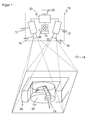
- FIG. 1 shows in a schematic three-dimensional representation and FIG. 2 in a block diagram, the structure of an embodiment of the sensor 10 according to the invention based on a three-dimensional stereoscopic camera.
- Two camera modules 12, 12 ' are mounted at a known fixed distance from each other. Both cameras 12, 12 'each record the image of a surveillance area 14.
- the cameras 12, 12 ' have an only indicated objective 16, 16' with an imaging optics and a front screen 17.
- the field of vision of this optic is in FIG. 1 represented by dashed lines, each forming a viewing pyramid, and encloses according to the invention, for example, 45 °.
- This image sensor 13 is a matrix-shaped pick-up chip which picks up a rectangular pixel image and can be for example a CCD or a CMOS sensor.
- the light source for the illumination source 18 is at least one laser or at least one LED.
- the illumination source 18 can generate a lighting pattern.
- a diffractive optical element 20 is arranged downstream in the optical axis, which deflects the light incident from the illumination source 18 only into specific subareas of the monitoring area 14.
- the resulting illumination pattern may be a regular, ie matrix-shaped, dot or circle pattern, but also a different illumination pattern.
- a controller 22 is connected with the two cameras 12, 12 'and the illumination source 18, a controller 22 is connected.
- the controller 22 switches the light pulses of the illumination source 18 and receives image signals from the two cameras 12, 12 '.
- the controller 22 calculates three-dimensional image data of the space region 14 by means of a stereoscopic disparity estimation.
- a robot arm 24 which on the one hand represents a source of danger, on the other hand carries out a visually assisted automation task, such as moving or screwing objects.
- a visually assisted automation task such as moving or screwing objects.
- the robot 24 When the robot 24 is moving, its radius of motion must not contain an object of inadmissibility and, in particular, no body part of operating personnel. Therefore, a virtual protective field 26 is placed around the robot arm 24, and the controller 22 evaluates the image data in this virtual protective field 26 to detect improper object interventions.
- the protective field 26 is preferably located in a part of the spatial region 14 in which there are no objects. As a result, it is easier for the evaluation unit 22 to recognize an impermissible object intervention, because any change in the field of view that is not due to image acquisition tolerances or the like is inadmissible.
- the invention also includes such embodiments in which previously permitted object interventions are taught into the protective field 26 and only a deviation from these permitted object interventions is recognized as an inadmissible object intervention.
- a warning or shutdown device 28 is used to output a warning or to secure the source of danger, ie the robot arm 24 is stopped in the illustrated example. It depends on the application, whether a warning is sufficient, or it is a two-stage protection provided in the first warned and is turned off only with continued object engagement or even deeper penetration.
- the senor 10 is designed fail-safe. This means, among other things, that the sensor 10 can test itself in cycles below the required response time and that the output to and the warning and shutdown device 28 itself is safe, designed for example two-channel. Likewise, the controller 22 itself is safe, so it evaluates two-channel or uses algorithms that can test themselves.
- the protective field 26 thus represents a security area or a part of a security area, which is checked in the manner described for security-relevant events.
- Safety tasks are performed in a safety evaluation 32 of the controller 22. Additionally is in FIG. 1 a cylindrical automation area 30 is shown around the robot arm 24. Image data from the automation area 30 are evaluated in an automation evaluation 34 of the controller 22.
- Such evaluations can be, for example, to check objects or materials for specific properties such as colors or sizes, their position or position in space or other properties and thus support automation tasks, such as grasping or sorting such objects or a quality inspection. The result of these visual assisting automation tasks is provided to an automation controller 36.
- a configuration device 40 is provided.
- this configuration device 40 is also a display device which is able to visualize the security areas 26 and the automation areas 30.
- the respective area can be entered manually in a non-exhaustive enumeration in the manner of a CAD program via a keyboard or a graphic user interface, imported from a file, or handed over from a control of the robot arm 24.
- a visual feature may be a code, a bar code or a light source operating at a particular wavelength, shape or pulse train.
- the code may be mounted on reflective tape to increase the detection range with active illumination 18 of the sensor 10.
- This visual feature may be attached to the robotic arm 24, in particular at pivot points, dangerous or exposed points, which then makes its usual movement to learn the configuration, but may also be moved by an operator through the space area 14 to access areas 26, 30 mark.
- an acoustic password for starting and ending the configuration mode, the operator can move through the spatial area and start and interrupt the configuration mode by pronouncing the password in order to mark areas 26, 30 at different locations.
- the visual feature may also be carried by a robot or a vehicle that travels the trajectory of a source of danger.
- the thus configured regions 26, 30 may be the same, ie static, for the entire operation, but they may alternatively change dynamically in a more flexible and costly application both in their position and in their extent, for example, in order to track movements of observed work equipment.
- the controller 22 also has a connection for further external sensors 42, such as position sensors or rotary encoders of the robot arm 24 or other sensors for generating spatially resolved information from the monitoring area 14, to supplement or correct the image data of the image sensor 13.
- further external sensors 42 such as position sensors or rotary encoders of the robot arm 24 or other sensors for generating spatially resolved information from the monitoring area 14, to supplement or correct the image data of the image sensor 13.
- FIG. 3 illustrates a schematic plan view of the monitoring area 14, in which a number of security areas 26a, 26b and a few automation areas 30a, 30b, 30c are illustrated. These areas also represent the areas of interest which the ROI device 38 predefines the image sensor 13. As shown in each case by dashed arrows, the evaluations of the protection zones 26a, 26b are assigned to one or more parallel evaluation threads or threads of the security evaluation 32, whereas the evaluations of the automation zones 30a, 30b, 30c are assigned to the same or to one or more further parallel evaluation threads of the automation evaluation 34. Parts of the monitoring area 14 in which there are no areas of interest 26, 30 are free areas in which no evaluations have to take place in order to conserve computing capacity.
- the invention also includes other three-dimensional image sensors, such as a runtime camera that emits light pulses or modulated light and closes from the light transit time to distances, or actively triangulating cameras, which distortions in the structure of the illumination pattern or the position of parts of the illumination pattern in the captured image to calculate distance data.
- a runtime camera that emits light pulses or modulated light and closes from the light transit time to distances
- actively triangulating cameras which distortions in the structure of the illumination pattern or the position of parts of the illumination pattern in the captured image to calculate distance data.
- a distance-resolving light receiver is a momentary light grid.
- a light grid consists of a plurality of arrayed light probes having a distance-measuring light receiver based on a time-of-flight or triangulation method using a matrix or line-type receiver or a spatially resolving diode (PSD, position sensing device) based.
- PSD spatially resolving diode
- One or more such triangulation-based momentary light grids thus form an approximation to a three-dimensional image sensor, which is included in the invention.
- multiple cameras 12 may be mounted in different positions for capturing image data from different perspectives. Their images are then billed together to form a set of two-dimensional image data before they are evaluated as described above in security areas 26 on the one hand and automation areas 30 on the other hand.
Landscapes
- Engineering & Computer Science (AREA)
- Physics & Mathematics (AREA)
- General Physics & Mathematics (AREA)
- Multimedia (AREA)
- Theoretical Computer Science (AREA)
- Length Measuring Devices By Optical Means (AREA)
Priority Applications (1)
| Application Number | Priority Date | Filing Date | Title |
|---|---|---|---|
| EP07119239.7A EP2053538B1 (fr) | 2007-10-25 | 2007-10-25 | Protection d'une zone de surveillance et support visuel d'un usinage automatisé |
Applications Claiming Priority (1)
| Application Number | Priority Date | Filing Date | Title |
|---|---|---|---|
| EP07119239.7A EP2053538B1 (fr) | 2007-10-25 | 2007-10-25 | Protection d'une zone de surveillance et support visuel d'un usinage automatisé |
Publications (2)
| Publication Number | Publication Date |
|---|---|
| EP2053538A1 true EP2053538A1 (fr) | 2009-04-29 |
| EP2053538B1 EP2053538B1 (fr) | 2014-02-26 |
Family
ID=39144516
Family Applications (1)
| Application Number | Title | Priority Date | Filing Date |
|---|---|---|---|
| EP07119239.7A Active EP2053538B1 (fr) | 2007-10-25 | 2007-10-25 | Protection d'une zone de surveillance et support visuel d'un usinage automatisé |
Country Status (1)
| Country | Link |
|---|---|
| EP (1) | EP2053538B1 (fr) |
Cited By (14)
| Publication number | Priority date | Publication date | Assignee | Title |
|---|---|---|---|---|
| US8873058B2 (en) | 2012-02-24 | 2014-10-28 | Sick Ag | Optical sensor |
| DE102013104265A1 (de) * | 2013-04-26 | 2014-10-30 | Pilz Gmbh & Co. Kg | Vorrichtung und Verfahren zum Absichern einer automatisiert arbeitenden Maschine |
| EP2818824A1 (fr) | 2013-06-28 | 2014-12-31 | Sick Ag | Appareil comprenant un capteur optoélectronique 3D et procédé de réconaissance d'objets |
| EP2819109A1 (fr) | 2013-06-28 | 2014-12-31 | Sick Ag | Appareil comprenant un capteur optoélectronique 3D et procédé de réconaissance d'objets |
| US9001330B2 (en) | 2012-03-07 | 2015-04-07 | Sick Ag | Attachment for placement onto an optical sensor and method of operating an optical sensor |
| US9140820B2 (en) | 2012-02-24 | 2015-09-22 | Sick Ag | Optical sensor and test method for testing the operability of an optical sensor |
| US9423244B2 (en) | 2013-04-08 | 2016-08-23 | Sick Ag | System and method for configuring a monitored zone of an optoelectronic monitoring device |
| EP3136314A1 (fr) | 2015-08-27 | 2017-03-01 | Arkite NV | Système de contrôle de la qualité d'une zone de travail d'un processus opérationnel |
| CN111226178A (zh) * | 2017-10-24 | 2020-06-02 | 罗伯特·博世有限公司 | 监视设备、工业系统、用于监视的方法及计算机程序 |
| CN111678026A (zh) * | 2019-03-11 | 2020-09-18 | 西克股份公司 | 机器的防护 |
| DE102019112085A1 (de) * | 2019-05-09 | 2020-11-12 | Rotoclear Gmbh | Kamerasystem |
| EP3933262A1 (fr) * | 2020-06-29 | 2022-01-05 | Herbert Waldmann GmbH & Co. KG | Luminaire, en particulier luminaire encastré ou à poser |
| CN113962572A (zh) * | 2021-10-27 | 2022-01-21 | 国网山东省电力公司莱阳市供电公司 | 变电站二次设备自动验收方法及终端设备 |
| US12260252B2 (en) | 2021-02-04 | 2025-03-25 | Sick Ag | Safety device and safety method for monitoring a machine |
Families Citing this family (3)
| Publication number | Priority date | Publication date | Assignee | Title |
|---|---|---|---|---|
| EP4390577B1 (fr) | 2022-12-22 | 2024-10-30 | Sick Ag | Surveillance d'au moins une machine |
| EP4650886B1 (fr) | 2024-05-17 | 2026-03-11 | Sick Ag | Dispositifs et procédés de sécurité |
| EP4650644A1 (fr) | 2024-05-17 | 2025-11-19 | Sick Ag | Dispositifs et procédés de sécurité |
Citations (4)
| Publication number | Priority date | Publication date | Assignee | Title |
|---|---|---|---|---|
| EP1457730A2 (fr) * | 2003-03-13 | 2004-09-15 | Omron Corporation | Dispositif de détection d'intrusion d'objets |
| EP1586423A1 (fr) * | 2002-12-10 | 2005-10-19 | HONDA MOTOR CO., Ltd. | Dispositif, procede et programme, de commande de robot, |
| EP1589279A2 (fr) | 2004-04-23 | 2005-10-26 | Sick Ag | Procédé pour la sécurité d'une machine-outil et capteur optoélectronique pour la mise en oeuvre d'un tel procédé. |
| WO2007085330A1 (fr) * | 2006-01-30 | 2007-08-02 | Abb Ab | Procédé et système permettant la supervision d'une zone de travail comportant un robot industriel |
-
2007
- 2007-10-25 EP EP07119239.7A patent/EP2053538B1/fr active Active
Patent Citations (4)
| Publication number | Priority date | Publication date | Assignee | Title |
|---|---|---|---|---|
| EP1586423A1 (fr) * | 2002-12-10 | 2005-10-19 | HONDA MOTOR CO., Ltd. | Dispositif, procede et programme, de commande de robot, |
| EP1457730A2 (fr) * | 2003-03-13 | 2004-09-15 | Omron Corporation | Dispositif de détection d'intrusion d'objets |
| EP1589279A2 (fr) | 2004-04-23 | 2005-10-26 | Sick Ag | Procédé pour la sécurité d'une machine-outil et capteur optoélectronique pour la mise en oeuvre d'un tel procédé. |
| WO2007085330A1 (fr) * | 2006-01-30 | 2007-08-02 | Abb Ab | Procédé et système permettant la supervision d'une zone de travail comportant un robot industriel |
Cited By (19)
| Publication number | Priority date | Publication date | Assignee | Title |
|---|---|---|---|---|
| US9140820B2 (en) | 2012-02-24 | 2015-09-22 | Sick Ag | Optical sensor and test method for testing the operability of an optical sensor |
| US8873058B2 (en) | 2012-02-24 | 2014-10-28 | Sick Ag | Optical sensor |
| US9001330B2 (en) | 2012-03-07 | 2015-04-07 | Sick Ag | Attachment for placement onto an optical sensor and method of operating an optical sensor |
| US9354169B2 (en) | 2012-03-07 | 2016-05-31 | Sick Ag | Attachment for placement onto an optical sensor and method of operating an optical sensor |
| EP2790040B1 (fr) * | 2013-04-08 | 2021-07-14 | Sick Ag | Système et procédé de configuration d'une zone de surveillance d'un dispositif de surveillance optoélectronique |
| US9423244B2 (en) | 2013-04-08 | 2016-08-23 | Sick Ag | System and method for configuring a monitored zone of an optoelectronic monitoring device |
| DE102013104265A1 (de) * | 2013-04-26 | 2014-10-30 | Pilz Gmbh & Co. Kg | Vorrichtung und Verfahren zum Absichern einer automatisiert arbeitenden Maschine |
| US10302251B2 (en) | 2013-04-26 | 2019-05-28 | Pilz Gmbh & Co. Kg | Apparatus and method for safeguarding an automatically operating machine |
| EP2818824A1 (fr) | 2013-06-28 | 2014-12-31 | Sick Ag | Appareil comprenant un capteur optoélectronique 3D et procédé de réconaissance d'objets |
| EP2819109A1 (fr) | 2013-06-28 | 2014-12-31 | Sick Ag | Appareil comprenant un capteur optoélectronique 3D et procédé de réconaissance d'objets |
| EP3136314A1 (fr) | 2015-08-27 | 2017-03-01 | Arkite NV | Système de contrôle de la qualité d'une zone de travail d'un processus opérationnel |
| CN111226178A (zh) * | 2017-10-24 | 2020-06-02 | 罗伯特·博世有限公司 | 监视设备、工业系统、用于监视的方法及计算机程序 |
| CN111226178B (zh) * | 2017-10-24 | 2023-12-08 | 罗伯特·博世有限公司 | 监视设备、工业系统、用于监视的方法及计算机程序 |
| CN111678026A (zh) * | 2019-03-11 | 2020-09-18 | 西克股份公司 | 机器的防护 |
| CN111678026B (zh) * | 2019-03-11 | 2023-05-16 | 西克股份公司 | 机器的防护 |
| DE102019112085A1 (de) * | 2019-05-09 | 2020-11-12 | Rotoclear Gmbh | Kamerasystem |
| EP3933262A1 (fr) * | 2020-06-29 | 2022-01-05 | Herbert Waldmann GmbH & Co. KG | Luminaire, en particulier luminaire encastré ou à poser |
| US12260252B2 (en) | 2021-02-04 | 2025-03-25 | Sick Ag | Safety device and safety method for monitoring a machine |
| CN113962572A (zh) * | 2021-10-27 | 2022-01-21 | 国网山东省电力公司莱阳市供电公司 | 变电站二次设备自动验收方法及终端设备 |
Also Published As
| Publication number | Publication date |
|---|---|
| EP2053538B1 (fr) | 2014-02-26 |
Similar Documents
| Publication | Publication Date | Title |
|---|---|---|
| EP2053538B1 (fr) | Protection d'une zone de surveillance et support visuel d'un usinage automatisé | |
| EP2023160B1 (fr) | Surveillance spatiale tridimensionnelle dotée d'un mode de configuration pour la détermination des champs de protection | |
| EP3709106B1 (fr) | Mise en sécurité d'une machine | |
| DE102009031732B3 (de) | Entfernungsmessender optoelektronischer Sensor | |
| EP3011225B1 (fr) | Dispositif et procédé pour protéger une machine fonctionnant de manière automatisée | |
| DE102019110882B4 (de) | Absichern eines beweglichen Maschinenteils | |
| EP2048557B1 (fr) | Capteur optoélectronique et dispositif mobile ainsi que son procédé de configuration | |
| EP2083209B1 (fr) | Système de sécurité destiné à la mesure sans contact de voies et/ou de vitesses | |
| EP3611422B1 (fr) | Dispositif capteur et procédé de sécurisation d'une zone de surveillance | |
| EP3744482B1 (fr) | Fixation d'une pièce de machine mobile | |
| DE102010007520B3 (de) | Sicherheitssteuerung mit einer Vielzahl von Anschlüssen für Sensoren | |
| EP3650740B1 (fr) | Système de sécurité et procédé de surveillance d'une machine | |
| EP3988256B1 (fr) | Fixation d'une pièce de machine mobile | |
| EP4102252B1 (fr) | Surveillance sûre d'une zone de protection au moyen d'une caméra tof | |
| EP3217195B1 (fr) | Capteur optique | |
| DE102023102951A1 (de) | Verfahren und berührungsloser Distanzsensor zum Absichern einer Maschine | |
| EP2819109B1 (fr) | Capteur optoélectronique 3D et procédé de reconnaissance d'objets | |
| AT517784B1 (de) | Verfahren zur automatisierten Steuerung einer Maschinenkomponente | |
| DE102020129823B4 (de) | Visualisieren eines Schutzfeldes | |
| EP1837586B1 (fr) | Dispositif de surveillance d'une zone dangereuse près d'une machine | |
| DE202020106491U1 (de) | Visualisieren eines Schutzfeldes | |
| DE102018101162A1 (de) | Messsystem und Verfahren zur extrinsischen Kalibrierung | |
| EP2527868A1 (fr) | Capteur de sécurité optoélectronique mesurant l'éloignement pour la surveillance d'une zone de surveillance | |
| DE102017004030B4 (de) | Verfahren und Vorrichtung zum Sichern eines Arbeitsraums | |
| EP2818824B1 (fr) | Appareil comprenant un capteur optoélectronique 3D et procédé de réconaissance d'objets |
Legal Events
| Date | Code | Title | Description |
|---|---|---|---|
| PUAI | Public reference made under article 153(3) epc to a published international application that has entered the european phase |
Free format text: ORIGINAL CODE: 0009012 |
|
| AK | Designated contracting states |
Kind code of ref document: A1 Designated state(s): AT BE BG CH CY CZ DE DK EE ES FI FR GB GR HU IE IS IT LI LT LU LV MC MT NL PL PT RO SE SI SK TR |
|
| AX | Request for extension of the european patent |
Extension state: AL BA HR MK RS |
|
| 17P | Request for examination filed |
Effective date: 20080423 |
|
| 17Q | First examination report despatched |
Effective date: 20090415 |
|
| AKX | Designation fees paid |
Designated state(s): AT BE BG CH CY CZ DE DK EE ES FI FR GB GR HU IE IS IT LI LT LU LV MC MT NL PL PT RO SE SI SK TR |
|
| GRAP | Despatch of communication of intention to grant a patent |
Free format text: ORIGINAL CODE: EPIDOSNIGR1 |
|
| INTG | Intention to grant announced |
Effective date: 20131031 |
|
| GRAS | Grant fee paid |
Free format text: ORIGINAL CODE: EPIDOSNIGR3 |
|
| GRAA | (expected) grant |
Free format text: ORIGINAL CODE: 0009210 |
|
| AK | Designated contracting states |
Kind code of ref document: B1 Designated state(s): AT BE BG CH CY CZ DE DK EE ES FI FR GB GR HU IE IS IT LI LT LU LV MC MT NL PL PT RO SE SI SK TR |
|
| REG | Reference to a national code |
Ref country code: GB Ref legal event code: FG4D Free format text: NOT ENGLISH |
|
| REG | Reference to a national code |
Ref country code: CH Ref legal event code: EP |
|
| REG | Reference to a national code |
Ref country code: AT Ref legal event code: REF Ref document number: 653975 Country of ref document: AT Kind code of ref document: T Effective date: 20140315 |
|
| REG | Reference to a national code |
Ref country code: DE Ref legal event code: R096 Ref document number: 502007012786 Country of ref document: DE Effective date: 20140403 |
|
| REG | Reference to a national code |
Ref country code: IE Ref legal event code: FG4D Free format text: LANGUAGE OF EP DOCUMENT: GERMAN |
|
| REG | Reference to a national code |
Ref country code: NL Ref legal event code: VDEP Effective date: 20140226 |
|
| REG | Reference to a national code |
Ref country code: LT Ref legal event code: MG4D |
|
| PG25 | Lapsed in a contracting state [announced via postgrant information from national office to epo] |
Ref country code: IS Free format text: LAPSE BECAUSE OF FAILURE TO SUBMIT A TRANSLATION OF THE DESCRIPTION OR TO PAY THE FEE WITHIN THE PRESCRIBED TIME-LIMIT Effective date: 20140626 Ref country code: LT Free format text: LAPSE BECAUSE OF FAILURE TO SUBMIT A TRANSLATION OF THE DESCRIPTION OR TO PAY THE FEE WITHIN THE PRESCRIBED TIME-LIMIT Effective date: 20140226 |
|
| PG25 | Lapsed in a contracting state [announced via postgrant information from national office to epo] |
Ref country code: NL Free format text: LAPSE BECAUSE OF FAILURE TO SUBMIT A TRANSLATION OF THE DESCRIPTION OR TO PAY THE FEE WITHIN THE PRESCRIBED TIME-LIMIT Effective date: 20140226 Ref country code: PT Free format text: LAPSE BECAUSE OF FAILURE TO SUBMIT A TRANSLATION OF THE DESCRIPTION OR TO PAY THE FEE WITHIN THE PRESCRIBED TIME-LIMIT Effective date: 20140626 Ref country code: FI Free format text: LAPSE BECAUSE OF FAILURE TO SUBMIT A TRANSLATION OF THE DESCRIPTION OR TO PAY THE FEE WITHIN THE PRESCRIBED TIME-LIMIT Effective date: 20140226 Ref country code: CY Free format text: LAPSE BECAUSE OF FAILURE TO SUBMIT A TRANSLATION OF THE DESCRIPTION OR TO PAY THE FEE WITHIN THE PRESCRIBED TIME-LIMIT Effective date: 20140226 Ref country code: SE Free format text: LAPSE BECAUSE OF FAILURE TO SUBMIT A TRANSLATION OF THE DESCRIPTION OR TO PAY THE FEE WITHIN THE PRESCRIBED TIME-LIMIT Effective date: 20140226 |
|
| PG25 | Lapsed in a contracting state [announced via postgrant information from national office to epo] |
Ref country code: LV Free format text: LAPSE BECAUSE OF FAILURE TO SUBMIT A TRANSLATION OF THE DESCRIPTION OR TO PAY THE FEE WITHIN THE PRESCRIBED TIME-LIMIT Effective date: 20140226 |
|
| PG25 | Lapsed in a contracting state [announced via postgrant information from national office to epo] |
Ref country code: DK Free format text: LAPSE BECAUSE OF FAILURE TO SUBMIT A TRANSLATION OF THE DESCRIPTION OR TO PAY THE FEE WITHIN THE PRESCRIBED TIME-LIMIT Effective date: 20140226 Ref country code: EE Free format text: LAPSE BECAUSE OF FAILURE TO SUBMIT A TRANSLATION OF THE DESCRIPTION OR TO PAY THE FEE WITHIN THE PRESCRIBED TIME-LIMIT Effective date: 20140226 Ref country code: CZ Free format text: LAPSE BECAUSE OF FAILURE TO SUBMIT A TRANSLATION OF THE DESCRIPTION OR TO PAY THE FEE WITHIN THE PRESCRIBED TIME-LIMIT Effective date: 20140226 Ref country code: RO Free format text: LAPSE BECAUSE OF FAILURE TO SUBMIT A TRANSLATION OF THE DESCRIPTION OR TO PAY THE FEE WITHIN THE PRESCRIBED TIME-LIMIT Effective date: 20140226 |
|
| REG | Reference to a national code |
Ref country code: DE Ref legal event code: R026 Ref document number: 502007012786 Country of ref document: DE |
|
| PG25 | Lapsed in a contracting state [announced via postgrant information from national office to epo] |
Ref country code: PL Free format text: LAPSE BECAUSE OF FAILURE TO SUBMIT A TRANSLATION OF THE DESCRIPTION OR TO PAY THE FEE WITHIN THE PRESCRIBED TIME-LIMIT Effective date: 20140226 Ref country code: SK Free format text: LAPSE BECAUSE OF FAILURE TO SUBMIT A TRANSLATION OF THE DESCRIPTION OR TO PAY THE FEE WITHIN THE PRESCRIBED TIME-LIMIT Effective date: 20140226 Ref country code: ES Free format text: LAPSE BECAUSE OF FAILURE TO SUBMIT A TRANSLATION OF THE DESCRIPTION OR TO PAY THE FEE WITHIN THE PRESCRIBED TIME-LIMIT Effective date: 20140226 |
|
| PLBI | Opposition filed |
Free format text: ORIGINAL CODE: 0009260 |
|
| 26 | Opposition filed |
Opponent name: LEUZE ELECTRONIC GMBH + CO. KG Effective date: 20141119 |
|
| PLAX | Notice of opposition and request to file observation + time limit sent |
Free format text: ORIGINAL CODE: EPIDOSNOBS2 |
|
| REG | Reference to a national code |
Ref country code: DE Ref legal event code: R026 Ref document number: 502007012786 Country of ref document: DE Effective date: 20141119 |
|
| PLBB | Reply of patent proprietor to notice(s) of opposition received |
Free format text: ORIGINAL CODE: EPIDOSNOBS3 |
|
| PG25 | Lapsed in a contracting state [announced via postgrant information from national office to epo] |
Ref country code: IT Free format text: LAPSE BECAUSE OF FAILURE TO SUBMIT A TRANSLATION OF THE DESCRIPTION OR TO PAY THE FEE WITHIN THE PRESCRIBED TIME-LIMIT Effective date: 20140226 |
|
| PG25 | Lapsed in a contracting state [announced via postgrant information from national office to epo] |
Ref country code: LU Free format text: LAPSE BECAUSE OF FAILURE TO SUBMIT A TRANSLATION OF THE DESCRIPTION OR TO PAY THE FEE WITHIN THE PRESCRIBED TIME-LIMIT Effective date: 20141025 Ref country code: SI Free format text: LAPSE BECAUSE OF FAILURE TO SUBMIT A TRANSLATION OF THE DESCRIPTION OR TO PAY THE FEE WITHIN THE PRESCRIBED TIME-LIMIT Effective date: 20140226 Ref country code: MC Free format text: LAPSE BECAUSE OF FAILURE TO SUBMIT A TRANSLATION OF THE DESCRIPTION OR TO PAY THE FEE WITHIN THE PRESCRIBED TIME-LIMIT Effective date: 20140226 |
|
| PG25 | Lapsed in a contracting state [announced via postgrant information from national office to epo] |
Ref country code: BE Free format text: LAPSE BECAUSE OF NON-PAYMENT OF DUE FEES Effective date: 20141031 |
|
| REG | Reference to a national code |
Ref country code: IE Ref legal event code: MM4A |
|
| REG | Reference to a national code |
Ref country code: FR Ref legal event code: PLFP Year of fee payment: 9 |
|
| PG25 | Lapsed in a contracting state [announced via postgrant information from national office to epo] |
Ref country code: IE Free format text: LAPSE BECAUSE OF NON-PAYMENT OF DUE FEES Effective date: 20141025 |
|
| REG | Reference to a national code |
Ref country code: AT Ref legal event code: MM01 Ref document number: 653975 Country of ref document: AT Kind code of ref document: T Effective date: 20141025 |
|
| PG25 | Lapsed in a contracting state [announced via postgrant information from national office to epo] |
Ref country code: AT Free format text: LAPSE BECAUSE OF NON-PAYMENT OF DUE FEES Effective date: 20141025 |
|
| PG25 | Lapsed in a contracting state [announced via postgrant information from national office to epo] |
Ref country code: BG Free format text: LAPSE BECAUSE OF FAILURE TO SUBMIT A TRANSLATION OF THE DESCRIPTION OR TO PAY THE FEE WITHIN THE PRESCRIBED TIME-LIMIT Effective date: 20140226 |
|
| PLCK | Communication despatched that opposition was rejected |
Free format text: ORIGINAL CODE: EPIDOSNREJ1 |
|
| PG25 | Lapsed in a contracting state [announced via postgrant information from national office to epo] |
Ref country code: GR Free format text: LAPSE BECAUSE OF FAILURE TO SUBMIT A TRANSLATION OF THE DESCRIPTION OR TO PAY THE FEE WITHIN THE PRESCRIBED TIME-LIMIT Effective date: 20140527 |
|
| PG25 | Lapsed in a contracting state [announced via postgrant information from national office to epo] |
Ref country code: MT Free format text: LAPSE BECAUSE OF FAILURE TO SUBMIT A TRANSLATION OF THE DESCRIPTION OR TO PAY THE FEE WITHIN THE PRESCRIBED TIME-LIMIT Effective date: 20140226 Ref country code: HU Free format text: LAPSE BECAUSE OF FAILURE TO SUBMIT A TRANSLATION OF THE DESCRIPTION OR TO PAY THE FEE WITHIN THE PRESCRIBED TIME-LIMIT; INVALID AB INITIO Effective date: 20071025 Ref country code: TR Free format text: LAPSE BECAUSE OF FAILURE TO SUBMIT A TRANSLATION OF THE DESCRIPTION OR TO PAY THE FEE WITHIN THE PRESCRIBED TIME-LIMIT Effective date: 20140226 |
|
| APBM | Appeal reference recorded |
Free format text: ORIGINAL CODE: EPIDOSNREFNO |
|
| APBP | Date of receipt of notice of appeal recorded |
Free format text: ORIGINAL CODE: EPIDOSNNOA2O |
|
| APAH | Appeal reference modified |
Free format text: ORIGINAL CODE: EPIDOSCREFNO |
|
| APBQ | Date of receipt of statement of grounds of appeal recorded |
Free format text: ORIGINAL CODE: EPIDOSNNOA3O |
|
| REG | Reference to a national code |
Ref country code: FR Ref legal event code: PLFP Year of fee payment: 10 |
|
| REG | Reference to a national code |
Ref country code: FR Ref legal event code: PLFP Year of fee payment: 11 |
|
| PGFP | Annual fee paid to national office [announced via postgrant information from national office to epo] |
Ref country code: FR Payment date: 20171023 Year of fee payment: 11 |
|
| PGFP | Annual fee paid to national office [announced via postgrant information from national office to epo] |
Ref country code: GB Payment date: 20171024 Year of fee payment: 11 |
|
| PGFP | Annual fee paid to national office [announced via postgrant information from national office to epo] |
Ref country code: CH Payment date: 20181025 Year of fee payment: 12 |
|
| GBPC | Gb: european patent ceased through non-payment of renewal fee |
Effective date: 20181025 |
|
| PG25 | Lapsed in a contracting state [announced via postgrant information from national office to epo] |
Ref country code: FR Free format text: LAPSE BECAUSE OF NON-PAYMENT OF DUE FEES Effective date: 20181031 |
|
| PG25 | Lapsed in a contracting state [announced via postgrant information from national office to epo] |
Ref country code: GB Free format text: LAPSE BECAUSE OF NON-PAYMENT OF DUE FEES Effective date: 20181025 |
|
| APAH | Appeal reference modified |
Free format text: ORIGINAL CODE: EPIDOSCREFNO |
|
| REG | Reference to a national code |
Ref country code: CH Ref legal event code: PL |
|
| PG25 | Lapsed in a contracting state [announced via postgrant information from national office to epo] |
Ref country code: CH Free format text: LAPSE BECAUSE OF NON-PAYMENT OF DUE FEES Effective date: 20191031 Ref country code: LI Free format text: LAPSE BECAUSE OF NON-PAYMENT OF DUE FEES Effective date: 20191031 |
|
| APBU | Appeal procedure closed |
Free format text: ORIGINAL CODE: EPIDOSNNOA9O |
|
| REG | Reference to a national code |
Ref country code: DE Ref legal event code: R100 Ref document number: 502007012786 Country of ref document: DE |
|
| PLBN | Opposition rejected |
Free format text: ORIGINAL CODE: 0009273 |
|
| STAA | Information on the status of an ep patent application or granted ep patent |
Free format text: STATUS: OPPOSITION REJECTED |
|
| 27O | Opposition rejected |
Effective date: 20201021 |
|
| REG | Reference to a national code |
Ref country code: DE Ref legal event code: R079 Ref document number: 502007012786 Country of ref document: DE Free format text: PREVIOUS MAIN CLASS: G06K0009000000 Ipc: G06V0010000000 |
|
| PGFP | Annual fee paid to national office [announced via postgrant information from national office to epo] |
Ref country code: DE Payment date: 20241022 Year of fee payment: 18 |