EP2053567A2 - Appareil de traitement d'une feuille de papier - Google Patents
Appareil de traitement d'une feuille de papier Download PDFInfo
- Publication number
- EP2053567A2 EP2053567A2 EP08018488A EP08018488A EP2053567A2 EP 2053567 A2 EP2053567 A2 EP 2053567A2 EP 08018488 A EP08018488 A EP 08018488A EP 08018488 A EP08018488 A EP 08018488A EP 2053567 A2 EP2053567 A2 EP 2053567A2
- Authority
- EP
- European Patent Office
- Prior art keywords
- paper sheet
- bill
- pair
- traveling route
- contact members
- Prior art date
- Legal status (The legal status is an assumption and is not a legal conclusion. Google has not performed a legal analysis and makes no representation as to the accuracy of the status listed.)
- Granted
Links
- 238000003780 insertion Methods 0.000 claims abstract description 84
- 230000037431 insertion Effects 0.000 claims abstract description 84
- 230000007246 mechanism Effects 0.000 claims abstract description 64
- 238000012545 processing Methods 0.000 claims abstract description 51
- 238000012937 correction Methods 0.000 claims description 20
- 238000000034 method Methods 0.000 description 32
- 230000008569 process Effects 0.000 description 30
- 238000011144 upstream manufacturing Methods 0.000 description 7
- 230000005540 biological transmission Effects 0.000 description 6
- 230000001276 controlling effect Effects 0.000 description 5
- 238000010586 diagram Methods 0.000 description 5
- 230000003287 optical effect Effects 0.000 description 5
- 238000013500 data storage Methods 0.000 description 4
- 108090000237 interleukin-24 Proteins 0.000 description 3
- 230000001105 regulatory effect Effects 0.000 description 3
- 101000760620 Homo sapiens Cell adhesion molecule 1 Proteins 0.000 description 2
- 101000710013 Homo sapiens Reversion-inducing cysteine-rich protein with Kazal motifs Proteins 0.000 description 2
- 238000001514 detection method Methods 0.000 description 2
- 230000000694 effects Effects 0.000 description 2
- 230000006870 function Effects 0.000 description 2
- 238000012986 modification Methods 0.000 description 2
- 230000004048 modification Effects 0.000 description 2
- 102100035353 Cyclin-dependent kinase 2-associated protein 1 Human genes 0.000 description 1
- 101000737813 Homo sapiens Cyclin-dependent kinase 2-associated protein 1 Proteins 0.000 description 1
- 101001139126 Homo sapiens Krueppel-like factor 6 Proteins 0.000 description 1
- 101000661816 Homo sapiens Suppression of tumorigenicity 18 protein Proteins 0.000 description 1
- 101000585359 Homo sapiens Suppressor of tumorigenicity 20 protein Proteins 0.000 description 1
- 102100029860 Suppressor of tumorigenicity 20 protein Human genes 0.000 description 1
- 238000010030 laminating Methods 0.000 description 1
- 230000001373 regressive effect Effects 0.000 description 1
Images


Classifications
-
- G—PHYSICS
- G07—CHECKING-DEVICES
- G07D—HANDLING OF COINS OR VALUABLE PAPERS, e.g. TESTING, SORTING BY DENOMINATIONS, COUNTING, DISPENSING, CHANGING OR DEPOSITING
- G07D7/00—Testing specially adapted to determine the identity or genuineness of valuable papers or for segregating those which are unacceptable, e.g. banknotes that are alien to a currency
- G07D7/16—Testing the dimensions
- G07D7/164—Thickness
-
- G—PHYSICS
- G07—CHECKING-DEVICES
- G07D—HANDLING OF COINS OR VALUABLE PAPERS, e.g. TESTING, SORTING BY DENOMINATIONS, COUNTING, DISPENSING, CHANGING OR DEPOSITING
- G07D11/00—Devices accepting coins; Devices accepting, dispensing, sorting or counting valuable papers
- G07D11/10—Mechanical details
- G07D11/16—Handling of valuable papers
Definitions
- the paper sheet conveyance mechanism includes a pair of conveyor rollers that hold (or nip) an inserted paper sheet therebetween to convey it toward the downstream side, and when an entrance sensor installed in the back of the insertion slot detects the paper sheet insertion, the paper sheet conveyance mechanism drives the pair of conveyor rollers to hold (or nip) the paper sheet therebetween to convey it toward the inside of the apparatus.
- a typical paper sheet processing apparatus when a user inserts a paper sheet into an insertion slot, an entrance sensor installed at an insertion slot portion detects the insertion, and the paper sheet processing apparatus drives a pair of conveyor rollers so as to hold (or nip) the paper sheet therebetween on the downstream side to hold (or nip) the paper sheet therebetween and convey it toward the downstream side.
- control device controls the driving force to move the at least either of the pair of contact members such that the pair of contact members are kept apart from each other before the paper sheet is inserted into the insertion slot and that the pair of contact members become closer to each other so as to hold the paper sheet when the sensor detects that the paper sheet is inserted into the insertion slot.
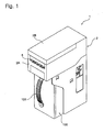
- FIGs. 1 to 6A are diagrams showing a configuration of a paper sheet processing apparatus as a bill processing apparatus according to the present embodiment.
- FIG. 1 is a perspective view showing the entire structure.
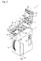
- FIG. 2 is a perspective view showing a state in which an open/close member is opened for a main body frame of an apparatus main body.
- FIG. 3 is a perspective view showing a structure of a power transmission part of the apparatus main body.
- FIG. 4 is a right side view schematically showing a traveling route for a bill to be inserted from an insertion slot.
- FIG. 5 is a left side view showing a schematic structure of a driving source and a driving force transmission mechanism to drive a bill conveyance mechanism.
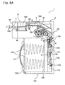
- FIG. 6A is a diagram showing a schematic structure of a driving force transmission mechanism to drive a presser plate installed in a bill housing part.
- the bill traveling route 3 is formed by the main body frame 2A and an open/close member 2B as described above, and in the present embodiment, the bill traveling route 3 is constituted of a first traveling route 3A provided so as to be connected to the bill insertion slot 5, and a second traveling route 3B extending toward the downstream side from the first traveling route 3A.
- a length L1 in a bill thickness direction of the first traveling route 3A is set to be longer than a length L2 in a bill thickness direction of the second traveling route 3B.
- a joint portion of the first traveling route 3A and the second traveling route 3B is bent by a predetermined angle (the bent portion is denoted by a reference symbol of 3D).
- the bent portion 3D may be arranged at any position on the upstream side of bill reading means 8 (e.g., bill reading device) to be described later.
- FIG. 6B is a partial enlarged view of a bent portion 3D as shown in FIG. 6A .
- the first traveling route 3A and the second traveling route 3B are jointed with a crossing angle of ⁇ such that the bill or a thin rigid plate is prevented from passing through the traveling route as the distance from the insertion slot 5 to the bent portion is longer and the height L1 of the traveling route is smaller such that it is difficult to pass beyond the joint portion.
- the bill traveling route 3 may have a constant length in the paper sheet thickness direction along the bill traveling direction, and may not have such a bent portion therein.
- the bill conveyance mechanism 6 is a mechanism capable of carrying a bill inserted from the bill insertion slot 5 along the inserting direction, and of feedback-carrying a bill in an inserted state toward the bill insertion slot 5.
- the bill conveyance mechanism 6 includes a motor 13 (refer to FIG. 5 ) serving as a driving source installed in the apparatus main body 2, and conveyor roller pairs (15A and 15B), (16A and 16B), and (17A and 17B) which are installed at predetermined intervals along the bill traveling direction in the bill traveling route 3, and are driven to rotate by the motor 13.
- the conveyor roller pairs are installed so as to be partially exposed to the bill traveling route 3, and all the pairs are rollers in which the conveyor rollers 15B, 16B, and 17B installed on the underside of the bill traveling route 3 are driven by the motor 13, and the conveyor rollers 15A, 16A, and 17A installed on the upper side are pinch-rollers driven according to these rollers.
- the conveyor roller pair (14A and 14B) as the contact members that first hold (or nip) a bill inserted from the bill insertion slot 5 therebetween, to carry it to the back side is, as shown in FIGs. 2 and 3 , installed at one place at the center position of the bill traveling route 3, and the conveyor roller pairs (15A and 15B), (16A and 16B), and (17A and 17B) which are disposed in the order at the downstream side thereof are respectively disposed at two places with predetermined intervals along the width direction of the bill traveling route 3.
- the upper roller 14A is normally set in a state where it is spaced from the lower roller 14B.
- the upper roller 14A is driven toward the lower conveyor roller 14B by the contact member driving mechanism 70 to hold (or nip) the inserted bill therebetween.
- the conveyor rollers 15B, 16B, and 17B installed on the underside of the bill traveling route 3 and the lower conveyor roller 14B constituting the contact members are, as shown in FIG. 5 , driven to rotate by the motor 13 and pulleys 15C, 16C, 17C, and 14C installed at the ends of the driving shafts of the respective conveyor rollers. That is, a driving pulley 13A is installed on the output shaft of the motor 13, and a driving belt 13B is wrapped around the pulleys 15C, 16C, 17C, and 14C installed at the ends of the driving shafts of the respective conveyor rollers as well as around the driving pulley 13A. In addition, tension pulleys are engaged at appropriate positions with the driving belt 13B, which prevents it from loosening.
- the movable piece passage detecting sensor 12 is to generate a sensed signal when it is sensed that a front end of the bill passes between a pair of left and right movable pieces constituting the skew correction mechanism 10, and the movable piece passage detecting sensor 12 is installed on the upstream side of the bill reading means (or bill reading device) 8.
- the movable piece passage detecting sensor 12 is also constituted of an optical sensor or a mechanical sensor in the same way as the aforementioned insertion detecting sensor.
- the bill reading means 8 reads bill information on the bill carried in a state in which the skew is eliminated by the skew correction mechanism 10 (and the bill is accurately positioned), and judges validity (authenticity) thereof.
- the bill reading means 8 may be constituted of a line sensor that performs reading of the bill such that the bill to be carried is irradiated with light on both sides, and transmitted light therethrough and reflected light therefrom are detected by a light receiving element.
- the line sensor is shown in the drawing, and an optical signal read by the line sensor is photoelectric-converted, and the signal is compared and checked with data of a legitimate bill stored in advance, which makes it possible to identify the authenticity of the bill to be carried.
- a main body frame 100A constituting the bill housing part 100 is formed into a substantially rectangular parallelepiped shape, and a placing plate 105 on which bills to be fed via the feed port 103 are stacked one after another, and a biasing means (biasing spring) 106 that pushes (or biases) the placing plate 105 toward a presser plate 115 which will be described later are provided inside the main body frame 100A.
- a press holding part 108 that holds and has a bill wait as it is, the bill being to be dropped, is provided so as to be continued from the feed port 103.
- a pair of regulatory walls (only either of them is illustrated in FIG. 4 , and the walls are omitted in FIG. 6A ) 110 is disposed so as to extend in the vertical direction on both sides of the press holding part 108 on the placing plate side.
- the pair of regulatory walls 110 serves to contact both sides of an uppermost bill to stably hold the bills to be stacked when bills are placed one after another on the placing plate 105 and the placing plate 105 is biased by the biasing means 106.
- the presser plate 115 that presses bills dropping into the press holding part 108 from the feed port 103 toward the placing plate 105 is installed in the main body frame 100A.
- the presser plate 115 is formed in a size to be capable of passing through a space between the pair of regulatory walls 110, and gets into the space to be driven to reciprocate between a position at which the bills are pressed against the placing plate 105 (a pressing position) and another position at which the press holding part 108 is opened (an initial position).
- the presser plate 115 is driven to reciprocate as described above by a presser plate driving mechanism 120 installed in the main body frame 100A.
- the presser plate driving mechanism 120 includes a pair of link members 115a and 115b, both ends of which are supported pivotally by the presser plate, so as to allow the presser plate 115 to reciprocate in an arrow A direction, and these link members 115a and 115b are connected at the respective center positions in an X-shaped configuration such that the respective ends opposite to each other are supported pivotally by a movable member 122 installed to be movable in a vertical direction (an arrow B direction).
- a rack is formed in the movable member 122, and a pinion 124A constituting the presser plate driving mechanism 120 is engaged with the rack.
- FIG. 7 is a perspective view showing an interior configuration of an open/close member arranged to the main frame
- FIG. 8 is a back view showing a configuration of a cam member and a driving source as shown in FIG. 7
- FIG. 9 is a perspective view showing a configuration of the cam member and the driving source as shown in FIG. 7
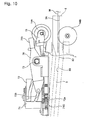
- FIG. 10 is a side view showing a state where the pair of contact members are spaced apart
- FIG. 11 is a side view showing a state where the bill is held (or nipped) by the pair of contact members.
- a spindle (or main shaft) 73 extending in a direction perpendicular to the bill traveling direction is provided at the bill insertion slot side at a frame 2F of the open/close member 2B.
- An arm 75 extending toward the bill insertion slot side is supported rotatably at the substantially center of the spindle 73, and the roller 14A is supported rotatably at the leading end thereof.
- a pair of swing members 76 and 77 are supported with respect to the spindle 73 on both sides of the arm 75 so as to rotate the arm 75 centering on the spindle 73.
- the rotary torque of the motor 71 is used for driving the cam member 72 connected to the gear train 71G as described above to rotate, and move the pair of swing members 76 and 77 up and down via the protrusions 76a and 76b engaged with the groove 72b formed in the outer circumferential surface of the cam member, to move the arm 75, i.e., the roller 14A up and down. Therefore, even when an attempt to move the roller 14A up and down is made for illicit purposes or the like, the swing members are difficult to swing because of the engagement with the cam, and the force is not transmitted to the motor 71, which makes it possible to effectively prevent the motor serving as the driving source from being broken and the like.
- the contact member driving mechanism 70 may comprise a solenoid or the like as a driving source that drives the roller 14A.
- a motor capable of rotating normally and reversely it is possible to control the roller 14A to become close to and apart from the roller 14B by the motor rotating normally and reversely. That is, by configuring the driving source with the motor, it suffices to control the driving of the motor 71 to stop at a position such that the pair of contact members become close to each other so as to hold (or nip) the bill therebetween and at another position such that the pair of contact members become apart from each other, which saves unnecessary electrical power for controlling the contact member to be moved. Further, an attempt can be made to make the motor silent as compared with a solenoid.
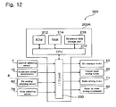
- control means that controls the driving of the bill conveyance mechanism 6, the bill reading means 8, and the contact member driving mechanism 70 will be described with reference to FIG. 12 .
- the control means 200 includes a control circuit board 200A that controls the operation of the respective drive units described above, and a CPU (Central Processing Unit) 210 constituting bill identification means, a ROM (Read Only Memory) 212, a RAM (Random Access Memory) 214, and a reference data storage part 216 are mounted on the control circuit board.
- a CPU Central Processing Unit
- ROM Read Only Memory
- RAM Random Access Memory
- various types of programs such as operation programs for the respective types of drive units such as the motor 13 that drives the above-described bill conveyance mechanism, the motor 20 that drives the presser plate, the roller driving motor 71 that drives the conveyor roller 14A as a part of the pair of rollers to come close to/to be spaced apart from the conveyor roller 14B, and the motor 40 that drives the skew driving mechanism 10 and an authenticity judgment program for identifying the bill that is read by the bill reading means 8; and permanent data are stored.
- the CPU 210 generates control signals according to the programs stored in the ROM 212, and carries out input and output of the signals to and from the respective drive units via an I/O port 220, in order to control the driving of the respective drive units.
- sensed signals from the insertion detecting sensor 7, the movable piece passage detecting sensor 12, and the roller detecting sensor 78 are input into the CPU 210 via the I/O port 220, and the driving control of the respective drive units is performed on the basis of these sensed signals.
- a bill reading detection sensor 80 constituting the above-described bill reading means 8 is connected to the CPU 210 via the I/O port 220, and bill reading data read by the bill reading detection sensor 80 is compared with the reference data stored in the reference data storage part 216, which allows a bill authenticity judgment process to be executed.
- control means 200 that controls the operation of the bill processing apparatus is mounted on one control circuit board 200A.
- control means 200 may be arranged in a dispersive manner on separate control circuit boards in accordance with respective functions thereof.
- the pair of rollers (14A and 14B) installed between the bill insertion slot 5 and the insertion detecting sensor 7 is in a state where the rollers are apart from each other as in an initial state (refer to ST22 and ST54 which will be described later).
- the bill traveling route 3 formed continuously from the bill insertion slot 5 is constituted of the first traveling route 3A and the second traveling route 3B, and as shown in FIG. 6A , the length L1 in the bill thickness direction of the first traveling route 3A is set to be longer than the length L2 in the bill thickness direction of the second traveling route 3B.
- the bill traveling route 3 is arranged to be bent at the bent portion 3D on the upstream side from the bill reading detecting sensor (line sensor) 80 that identifies the authenticity of the paper sheet, even if a thin rigid member such as a ruler is inserted into the bill traveling route by way of vandalization or fraudulent activity, the member cannot be inserted beyond the bent portion 3D, which makes it possible to effectively prevent the important components such as the bill reading detecting sensor 80 from being tampered.
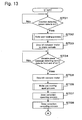
- the holding process by the pair of rollers is executed in accordance with the procedure shown in FIG. 16 . That is, the motor 71 for driving the rollers is driven to rotate normally (ST61), to move the upper roller 14A toward the lower roller 14B by the cam member 72 and the pair of swing members 76 and 77, and when the roller detecting sensor 78 detects the detecting piece 76b, the motor 71 for driving the rollers is stopped (ST62, ST63).
- the bill conveyor motor 13 When the bill is held (or nipped) between the pair of rollers (14A and 14B), the bill conveyor motor 13 is driven to rotate normally (ST03). The bill is conveyed toward the inside of the apparatus by the pair of rollers (14A and 14B), and when the movable piece passage detecting sensor 12 disposed on the downstream side from the skew correction mechanism 10 detects the leading end of the bill, the bill conveyor motor is stopped (ST04, ST05). At this time, the bill is located between the pair of movable pieces 10A constituting the skew correction mechanism 10.
- a spacing process of the pair of rollers is executed (ST06).
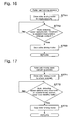
- the spacing process of the pair of rollers is executed in accordance with the procedure shown in FIG. 17 . That is, the motor 71 for driving the rollers is driven to rotate reversely (ST71), to move the upper roller 14A so as to be apart from the lower roller 14B by the cam member 72 and the pair of swing members 76 and 77, and when the roller detecting sensor 78 detects that the detecting piece 76b is separated, the motor 71 for driving the rollers is stopped (ST72, ST73). By this operation, the roller 14A is spaced from the roller 14B such that no load is applied to the bill.
- a skew correction operating process is executed in this state (ST07).
- the skew correction operating process is achieved by driving the motor 40 for the skew correction mechanism to rotate normally to drive the pair of movable pieces 10A to become close to each other. That is, the bill is moved so as to be positioned in the center by the movable pieces 10A contacting both sides of the bill, and its skew is corrected thereby, and the bill is positioned at the accurate center position.
- a skew correction canceling process is executed (ST08). This process is executed by moving the pair of moveable pieces 10A apart from each other by making the motor 40 for the above-mentioned skew correction mechanism driven to rotate reversely such that the pair of moveable pieces 10A are moved apart.
- the bill conveyor motor 13 is driven by a predetermined amount so as to stop the bill at a predetermined position (an escrow position; a position at which the bill is conveyed toward the downstream by 13 mm from the center position of the bill reading means 8), and at this time, a bill authenticity judgment process is executed in the control means 200 (ST12 to ST15).
- the bill conveyor motor 13 is driven to normally rotate to convey the bill toward the bill housing part 100 (ST19). Thereafter, when it is sensed that the bill is transferred to the bill housing part 100 (transferred to the press holding part 108 through the feed port 103) (ST20), the driving to normally rotate the above-described bill conveyor motor 13 is stopped (ST21) as well as the spacing process of the pair of rollers is executed (ST22, ST71 - ST73), and the series of processes is completed.
- the bill conveyor motor 13 is driven to rotate reversely such that the bill staying at the escrow position is conveyed toward the bill insertion slot 5 (ST51). Then, when the insertion detecting sensor 7 detects the back end of the bill returned toward the bill insertion slot 5 (ST52; Yes), the reverse rotation of the bill conveyor motor 13 is stopped (ST53) and the roller pair moving apart process is executed (ST54, ST71 - ST73) such that the pair of rollers holding the bill are moved apart, and the series of processes are completed.
- the present invention has been described above. However, the present invention is not limited to the above-described embodiment, and various modifications can be implemented.
- the pair of contact members installed in the vicinity of the bill insertion slot 5 to hold the bill therebetween has been described as the roller pair (14A and 14B).
- the pair of contact members may be appropriately modified such that one of the contact members may be a roller member and the other may be a belt member as well as both may be belt members.
- the lower roller 14B is configured to be driven to rotate.
- the upper roller 14A may be configured to be driven to rotate.
- the driving source that drives the various types of driving members or the mechanism for transmitting power from the driving source have been merely shown as examples, and modifications thereof can be appropriately made.
- height (or thickness) of the paper sheet insertion slot may be shorter than a thickness of the folded or twisted paper sheet such that the paper sheet may not be able to be drawn into the inside of the apparatus. Therefore, the paper sheet processing apparatus may not be able to convey the bill toward the paper sheet identification part.
- a paper sheet processing apparatus comprises: an insertion slot into which a paper sheet is inserted, a paper sheet conveyance mechanism which conveys the paper sheet inserted into the insertion slot, a paper sheet traveling route through which the paper sheet is conveyed to move by the paper sheet conveyance mechanism, a sensor which detects the paper sheet existence in the paper sheet traveling route, a pair of contact members which holds the paper sheet inserted into the insertion slot therebetween, a driving source which moves one of the pair of contact members toward the other contact member, and a control device which controls the driving of the driving source. And in the paper sheet processing apparatus, either of the pair of contact members is driven to convey the paper sheet by the paper sheet conveyance mechanism.
- the control device keeps the pair of contact members apart until the paper sheet is inserted into the insertion slot.
- the control device controls one of the pair of contact members to move toward the other so as to hold (or nip) the paper sheet therebetween.
- the paper sheet processing apparatus having the above-described configuration, when the user inserts the paper sheet into the insertion slot, one of the pair of contact members is moved toward the other contact member so as to hold the paper sheet between the pair of contact members after the existence of the paper sheet in the paper sheet traveling route is confirmed by the sensor. That is, since the pair of contact members is spaced therebetween until the existence of the paper sheet is detected, even if the paper sheet inserted into the insertion slot is folded, twisted, or wrinkled, the paper sheet can be surely inserted into the pair of contact members, and thereafter, when one contact member moves toward the other contact member, the paper sheet is held between the contact members, which achieves reliable conveyance.
- the pair of contact members are installed inside the insertion slot, but outer than the paper sheet detecting sensor.
- the pair of contact members are kept apart from each other such that the paper sheet can be inserted more smoothly.
- a paper sheet identification part that identifies the authenticity of a paper sheet is provided in the paper sheet traveling route. And the paper sheet traveling route is bent on the upstream side from the paper sheet identification part.
- the paper sheet conveyance mechanism includes a swing member pivotally supporting one of the pair of contact members.
- the contact member pivotally supported by the swing member is pressed against the other contact member by a spring.
- the moving contact member presses the paper sheet with biasing force of the spring, and can be spaced from the other contact member against the biased force by the spring. Therefore, the moving contact member can slidingly contact the paper sheet with appropriate biased force.
- the driving source comprises a motor which enables one of the pair of contact members to move toward the other contact member.
- one of the contact members moves toward the other contact member by driving the motor.
- the motor At a position where the pair of contact members contact with each other, it suffices to stop the driving of the motor since a position of the conveyor member is not controlled by a solenoid. Therefore, it is not necessary to provide electrical power for controlling the moving contact member.
- a paper sheet processing apparatus capable of stably conveying even a severely-damaged paper sheet toward the inside of the apparatus can be obtained.
Landscapes
- Physics & Mathematics (AREA)
- General Physics & Mathematics (AREA)
- Inspection Of Paper Currency And Valuable Securities (AREA)
- Delivering By Means Of Belts And Rollers (AREA)
- Controlling Sheets Or Webs (AREA)
Applications Claiming Priority (1)
| Application Number | Priority Date | Filing Date | Title |
|---|---|---|---|
| JP2007276602A JP5164255B2 (ja) | 2007-10-24 | 2007-10-24 | 紙葉処理装置 |
Publications (3)
| Publication Number | Publication Date |
|---|---|
| EP2053567A2 true EP2053567A2 (fr) | 2009-04-29 |
| EP2053567A3 EP2053567A3 (fr) | 2009-05-06 |
| EP2053567B1 EP2053567B1 (fr) | 2012-07-04 |
Family
ID=40377520
Family Applications (1)
| Application Number | Title | Priority Date | Filing Date |
|---|---|---|---|
| EP08018488A Active EP2053567B1 (fr) | 2007-10-24 | 2008-10-22 | Appareil de traitement d'une feuille de papier |
Country Status (3)
| Country | Link |
|---|---|
| US (1) | US7708273B2 (fr) |
| EP (1) | EP2053567B1 (fr) |
| JP (1) | JP5164255B2 (fr) |
Cited By (1)
| Publication number | Priority date | Publication date | Assignee | Title |
|---|---|---|---|---|
| GB2575248A (en) * | 2018-06-28 | 2020-01-08 | Innovative Tech Ltd | A banknote acceptor feeder device |
Families Citing this family (3)
| Publication number | Priority date | Publication date | Assignee | Title |
|---|---|---|---|---|
| CN106629198A (zh) * | 2016-11-08 | 2017-05-10 | 浙江维融电子科技股份有限公司 | 一种票据收集箱 |
| CN113168745B (zh) * | 2018-12-03 | 2023-11-14 | 克兰佩门特创新股份有限公司 | 不带空转辊的文件输送路径 |
| US11734983B1 (en) | 2018-12-18 | 2023-08-22 | Cummins-Allison Corp. | Banknote transport mechanisms and methods |
Citations (1)
| Publication number | Priority date | Publication date | Assignee | Title |
|---|---|---|---|---|
| JP2005115811A (ja) | 2003-10-10 | 2005-04-28 | Japan Cash Machine Co Ltd | 有価紙葉鑑別装置 |
Family Cites Families (19)
| Publication number | Priority date | Publication date | Assignee | Title |
|---|---|---|---|---|
| JPS56136736A (en) * | 1980-03-28 | 1981-10-26 | Fujitsu Ltd | Feeder for paper or the like |
| US5564544A (en) * | 1994-04-19 | 1996-10-15 | Kabushiki Kaisha Ace Denken | Bank note conveying apparatus |
| EP1051692B1 (fr) * | 1998-01-07 | 2007-04-04 | MEI, Inc. | Dispositif permettant d'empiler et de stocker des supports flexibles |
| JP3804384B2 (ja) * | 2000-01-27 | 2006-08-02 | 松下電器産業株式会社 | 自動販売機 |
| JP2002255393A (ja) * | 2001-02-26 | 2002-09-11 | Oki Electric Ind Co Ltd | 媒体処理装置 |
| US8276734B2 (en) * | 2001-03-21 | 2012-10-02 | Japan Cash Machine, Co., Ltd. | Bill validator with centering device |
| JP4261078B2 (ja) * | 2001-03-21 | 2009-04-30 | 日本金銭機械株式会社 | 紙幣中心整合装置を備えた紙幣鑑別装置 |
| JP2002288707A (ja) * | 2001-03-28 | 2002-10-04 | Fuji Electric Co Ltd | 紙葉類一括投入装置 |
| JP4479129B2 (ja) * | 2001-06-11 | 2010-06-09 | 富士電機リテイルシステムズ株式会社 | 紙幣識別装置 |
| JP4370736B2 (ja) * | 2001-06-12 | 2009-11-25 | 富士電機リテイルシステムズ株式会社 | 紙幣処理装置 |
| JP2003132393A (ja) * | 2001-10-19 | 2003-05-09 | Fuji Electric Co Ltd | 紙葉類処理装置 |
| AU2003902702A0 (en) * | 2003-05-30 | 2003-06-19 | Astrosys International Ltd | Currency note identification and validation |
| JP2005018688A (ja) * | 2003-06-30 | 2005-01-20 | Asahi Seiko Kk | 反射式光学センサを用いる紙幣識別装置 |
| US20050183926A1 (en) * | 2004-02-23 | 2005-08-25 | Deaville David C. | Document stacker with fault detection |
| JP4720161B2 (ja) * | 2004-12-01 | 2011-07-13 | セイコーエプソン株式会社 | 複合処理装置及びその制御方法 |
| US7651083B2 (en) * | 2006-09-21 | 2010-01-26 | Digital Check Corporation | Conveying apparatus and method |
| US20080190730A1 (en) * | 2007-01-29 | 2008-08-14 | Microsystem Controls Pty Ltd | Currency note and ticket processing apparatus |
| US7762547B2 (en) * | 2007-09-03 | 2010-07-27 | Universal Entertainment Corporation | Bill processing apparatus |
| JP5269506B2 (ja) * | 2007-10-24 | 2013-08-21 | 株式会社ユニバーサルエンターテインメント | 紙幣処理装置 |
-
2007
- 2007-10-24 JP JP2007276602A patent/JP5164255B2/ja active Active
-
2008
- 2008-10-22 EP EP08018488A patent/EP2053567B1/fr active Active
- 2008-10-24 US US12/257,899 patent/US7708273B2/en active Active
Patent Citations (1)
| Publication number | Priority date | Publication date | Assignee | Title |
|---|---|---|---|---|
| JP2005115811A (ja) | 2003-10-10 | 2005-04-28 | Japan Cash Machine Co Ltd | 有価紙葉鑑別装置 |
Cited By (3)
| Publication number | Priority date | Publication date | Assignee | Title |
|---|---|---|---|---|
| GB2575248A (en) * | 2018-06-28 | 2020-01-08 | Innovative Tech Ltd | A banknote acceptor feeder device |
| GB2575248B (en) * | 2018-06-28 | 2020-09-02 | Innovative Tech Ltd | A banknote acceptor feeder device |
| US11574517B2 (en) | 2018-06-28 | 2023-02-07 | Innovative Technology Limited | Banknote acceptor feeder device |
Also Published As
| Publication number | Publication date |
|---|---|
| JP2009104462A (ja) | 2009-05-14 |
| EP2053567B1 (fr) | 2012-07-04 |
| US20090121415A1 (en) | 2009-05-14 |
| US7708273B2 (en) | 2010-05-04 |
| JP5164255B2 (ja) | 2013-03-21 |
| EP2053567A3 (fr) | 2009-05-06 |
Similar Documents
| Publication | Publication Date | Title |
|---|---|---|
| AU2009203335B2 (en) | Paper sheet treating apparatus | |
| JP5188167B2 (ja) | 紙葉類処理装置 | |
| JP5317263B2 (ja) | 紙葉類処理装置 | |
| JP5269506B2 (ja) | 紙幣処理装置 | |
| JP5124254B2 (ja) | 紙幣処理装置 | |
| US8387977B2 (en) | Paper sheet processing device | |
| EP2030925A2 (fr) | Appareil de traitement des factures | |
| JP5184062B2 (ja) | 紙葉類処理装置 | |
| US8640849B2 (en) | Paper sheet processing device | |
| EP2053567A2 (fr) | Appareil de traitement d'une feuille de papier | |
| JP5546071B2 (ja) | 紙葉類処理装置及び紙葉類処理システム | |
| JP5091619B2 (ja) | 紙幣処理装置 | |
| KR20060132482A (ko) | 지폐 처리 장치 | |
| JP2011048428A (ja) | 紙幣識別装置 | |
| JP5091593B2 (ja) | 紙幣処理装置 | |
| JP5269424B2 (ja) | 紙葉類処理装置 | |
| HK1152695B (en) | Sheet stacking apparatus | |
| JP2004280552A (ja) | 印刷紙葉類の識別装置 | |
| HK1152695A1 (en) | Sheet stacking apparatus |
Legal Events
| Date | Code | Title | Description |
|---|---|---|---|
| PUAI | Public reference made under article 153(3) epc to a published international application that has entered the european phase |
Free format text: ORIGINAL CODE: 0009012 |
|
| PUAL | Search report despatched |
Free format text: ORIGINAL CODE: 0009013 |
|
| AK | Designated contracting states |
Kind code of ref document: A2 Designated state(s): AT BE BG CH CY CZ DE DK EE ES FI FR GB GR HR HU IE IS IT LI LT LU LV MC MT NL NO PL PT RO SE SI SK TR |
|
| AX | Request for extension of the european patent |
Extension state: AL BA MK RS |
|
| AK | Designated contracting states |
Kind code of ref document: A3 Designated state(s): AT BE BG CH CY CZ DE DK EE ES FI FR GB GR HR HU IE IS IT LI LT LU LV MC MT NL NO PL PT RO SE SI SK TR |
|
| AX | Request for extension of the european patent |
Extension state: AL BA MK RS |
|
| 17P | Request for examination filed |
Effective date: 20091106 |
|
| AKX | Designation fees paid |
Designated state(s): AT BE BG CH CY CZ DE DK EE ES FI FR GB GR HR HU IE IS IT LI LT LU LV MC MT NL NO PL PT RO SE SI SK TR |
|
| 17Q | First examination report despatched |
Effective date: 20100205 |
|
| RAP1 | Party data changed (applicant data changed or rights of an application transferred) |
Owner name: UNIVERSAL ENTERTAINMENT CORPORATION |
|
| GRAP | Despatch of communication of intention to grant a patent |
Free format text: ORIGINAL CODE: EPIDOSNIGR1 |
|
| GRAS | Grant fee paid |
Free format text: ORIGINAL CODE: EPIDOSNIGR3 |
|
| GRAA | (expected) grant |
Free format text: ORIGINAL CODE: 0009210 |
|
| AK | Designated contracting states |
Kind code of ref document: B1 Designated state(s): AT BE BG CH CY CZ DE DK EE ES FI FR GB GR HR HU IE IS IT LI LT LU LV MC MT NL NO PL PT RO SE SI SK TR |
|
| REG | Reference to a national code |
Ref country code: GB Ref legal event code: FG4D |
|
| REG | Reference to a national code |
Ref country code: CH Ref legal event code: EP |
|
| REG | Reference to a national code |
Ref country code: AT Ref legal event code: REF Ref document number: 565411 Country of ref document: AT Kind code of ref document: T Effective date: 20120715 |
|
| REG | Reference to a national code |
Ref country code: IE Ref legal event code: FG4D |
|
| REG | Reference to a national code |
Ref country code: DE Ref legal event code: R096 Ref document number: 602008016939 Country of ref document: DE Effective date: 20120830 |
|
| REG | Reference to a national code |
Ref country code: AT Ref legal event code: MK05 Ref document number: 565411 Country of ref document: AT Kind code of ref document: T Effective date: 20120704 |
|
| REG | Reference to a national code |
Ref country code: NL Ref legal event code: VDEP Effective date: 20120704 |
|
| PG25 | Lapsed in a contracting state [announced via postgrant information from national office to epo] |
Ref country code: SI Free format text: LAPSE BECAUSE OF FAILURE TO SUBMIT A TRANSLATION OF THE DESCRIPTION OR TO PAY THE FEE WITHIN THE PRESCRIBED TIME-LIMIT Effective date: 20120704 |
|
| REG | Reference to a national code |
Ref country code: LT Ref legal event code: MG4D Effective date: 20120704 |
|
| PG25 | Lapsed in a contracting state [announced via postgrant information from national office to epo] |
Ref country code: IS Free format text: LAPSE BECAUSE OF FAILURE TO SUBMIT A TRANSLATION OF THE DESCRIPTION OR TO PAY THE FEE WITHIN THE PRESCRIBED TIME-LIMIT Effective date: 20121104 Ref country code: CY Free format text: LAPSE BECAUSE OF FAILURE TO SUBMIT A TRANSLATION OF THE DESCRIPTION OR TO PAY THE FEE WITHIN THE PRESCRIBED TIME-LIMIT Effective date: 20120704 Ref country code: HR Free format text: LAPSE BECAUSE OF FAILURE TO SUBMIT A TRANSLATION OF THE DESCRIPTION OR TO PAY THE FEE WITHIN THE PRESCRIBED TIME-LIMIT Effective date: 20120704 Ref country code: NO Free format text: LAPSE BECAUSE OF FAILURE TO SUBMIT A TRANSLATION OF THE DESCRIPTION OR TO PAY THE FEE WITHIN THE PRESCRIBED TIME-LIMIT Effective date: 20121004 Ref country code: AT Free format text: LAPSE BECAUSE OF FAILURE TO SUBMIT A TRANSLATION OF THE DESCRIPTION OR TO PAY THE FEE WITHIN THE PRESCRIBED TIME-LIMIT Effective date: 20120704 Ref country code: FI Free format text: LAPSE BECAUSE OF FAILURE TO SUBMIT A TRANSLATION OF THE DESCRIPTION OR TO PAY THE FEE WITHIN THE PRESCRIBED TIME-LIMIT Effective date: 20120704 Ref country code: LT Free format text: LAPSE BECAUSE OF FAILURE TO SUBMIT A TRANSLATION OF THE DESCRIPTION OR TO PAY THE FEE WITHIN THE PRESCRIBED TIME-LIMIT Effective date: 20120704 Ref country code: BE Free format text: LAPSE BECAUSE OF FAILURE TO SUBMIT A TRANSLATION OF THE DESCRIPTION OR TO PAY THE FEE WITHIN THE PRESCRIBED TIME-LIMIT Effective date: 20120704 |
|
| PG25 | Lapsed in a contracting state [announced via postgrant information from national office to epo] |
Ref country code: GR Free format text: LAPSE BECAUSE OF FAILURE TO SUBMIT A TRANSLATION OF THE DESCRIPTION OR TO PAY THE FEE WITHIN THE PRESCRIBED TIME-LIMIT Effective date: 20121005 Ref country code: LV Free format text: LAPSE BECAUSE OF FAILURE TO SUBMIT A TRANSLATION OF THE DESCRIPTION OR TO PAY THE FEE WITHIN THE PRESCRIBED TIME-LIMIT Effective date: 20120704 Ref country code: SE Free format text: LAPSE BECAUSE OF FAILURE TO SUBMIT A TRANSLATION OF THE DESCRIPTION OR TO PAY THE FEE WITHIN THE PRESCRIBED TIME-LIMIT Effective date: 20120704 Ref country code: PT Free format text: LAPSE BECAUSE OF FAILURE TO SUBMIT A TRANSLATION OF THE DESCRIPTION OR TO PAY THE FEE WITHIN THE PRESCRIBED TIME-LIMIT Effective date: 20121105 Ref country code: PL Free format text: LAPSE BECAUSE OF FAILURE TO SUBMIT A TRANSLATION OF THE DESCRIPTION OR TO PAY THE FEE WITHIN THE PRESCRIBED TIME-LIMIT Effective date: 20120704 |
|
| PG25 | Lapsed in a contracting state [announced via postgrant information from national office to epo] |
Ref country code: NL Free format text: LAPSE BECAUSE OF FAILURE TO SUBMIT A TRANSLATION OF THE DESCRIPTION OR TO PAY THE FEE WITHIN THE PRESCRIBED TIME-LIMIT Effective date: 20120704 |
|
| PG25 | Lapsed in a contracting state [announced via postgrant information from national office to epo] |
Ref country code: RO Free format text: LAPSE BECAUSE OF FAILURE TO SUBMIT A TRANSLATION OF THE DESCRIPTION OR TO PAY THE FEE WITHIN THE PRESCRIBED TIME-LIMIT Effective date: 20120704 Ref country code: DK Free format text: LAPSE BECAUSE OF FAILURE TO SUBMIT A TRANSLATION OF THE DESCRIPTION OR TO PAY THE FEE WITHIN THE PRESCRIBED TIME-LIMIT Effective date: 20120704 Ref country code: EE Free format text: LAPSE BECAUSE OF FAILURE TO SUBMIT A TRANSLATION OF THE DESCRIPTION OR TO PAY THE FEE WITHIN THE PRESCRIBED TIME-LIMIT Effective date: 20120704 Ref country code: CZ Free format text: LAPSE BECAUSE OF FAILURE TO SUBMIT A TRANSLATION OF THE DESCRIPTION OR TO PAY THE FEE WITHIN THE PRESCRIBED TIME-LIMIT Effective date: 20120704 Ref country code: ES Free format text: LAPSE BECAUSE OF FAILURE TO SUBMIT A TRANSLATION OF THE DESCRIPTION OR TO PAY THE FEE WITHIN THE PRESCRIBED TIME-LIMIT Effective date: 20121015 |
|
| PLBE | No opposition filed within time limit |
Free format text: ORIGINAL CODE: 0009261 |
|
| STAA | Information on the status of an ep patent application or granted ep patent |
Free format text: STATUS: NO OPPOSITION FILED WITHIN TIME LIMIT |
|
| PG25 | Lapsed in a contracting state [announced via postgrant information from national office to epo] |
Ref country code: IT Free format text: LAPSE BECAUSE OF FAILURE TO SUBMIT A TRANSLATION OF THE DESCRIPTION OR TO PAY THE FEE WITHIN THE PRESCRIBED TIME-LIMIT Effective date: 20120704 Ref country code: MC Free format text: LAPSE BECAUSE OF NON-PAYMENT OF DUE FEES Effective date: 20121031 Ref country code: SK Free format text: LAPSE BECAUSE OF FAILURE TO SUBMIT A TRANSLATION OF THE DESCRIPTION OR TO PAY THE FEE WITHIN THE PRESCRIBED TIME-LIMIT Effective date: 20120704 |
|
| REG | Reference to a national code |
Ref country code: CH Ref legal event code: PL |
|
| 26N | No opposition filed |
Effective date: 20130405 |
|
| REG | Reference to a national code |
Ref country code: IE Ref legal event code: MM4A |
|
| REG | Reference to a national code |
Ref country code: FR Ref legal event code: ST Effective date: 20130628 |
|
| PG25 | Lapsed in a contracting state [announced via postgrant information from national office to epo] |
Ref country code: BG Free format text: LAPSE BECAUSE OF FAILURE TO SUBMIT A TRANSLATION OF THE DESCRIPTION OR TO PAY THE FEE WITHIN THE PRESCRIBED TIME-LIMIT Effective date: 20121004 Ref country code: LI Free format text: LAPSE BECAUSE OF NON-PAYMENT OF DUE FEES Effective date: 20121031 Ref country code: DE Free format text: LAPSE BECAUSE OF NON-PAYMENT OF DUE FEES Effective date: 20130501 Ref country code: IE Free format text: LAPSE BECAUSE OF NON-PAYMENT OF DUE FEES Effective date: 20121022 Ref country code: CH Free format text: LAPSE BECAUSE OF NON-PAYMENT OF DUE FEES Effective date: 20121031 |
|
| REG | Reference to a national code |
Ref country code: DE Ref legal event code: R097 Ref document number: 602008016939 Country of ref document: DE Effective date: 20130405 |
|
| REG | Reference to a national code |
Ref country code: DE Ref legal event code: R119 Ref document number: 602008016939 Country of ref document: DE Effective date: 20130501 |
|
| PG25 | Lapsed in a contracting state [announced via postgrant information from national office to epo] |
Ref country code: FR Free format text: LAPSE BECAUSE OF NON-PAYMENT OF DUE FEES Effective date: 20121031 |
|
| PG25 | Lapsed in a contracting state [announced via postgrant information from national office to epo] |
Ref country code: MT Free format text: LAPSE BECAUSE OF FAILURE TO SUBMIT A TRANSLATION OF THE DESCRIPTION OR TO PAY THE FEE WITHIN THE PRESCRIBED TIME-LIMIT Effective date: 20120704 |
|
| PG25 | Lapsed in a contracting state [announced via postgrant information from national office to epo] |
Ref country code: TR Free format text: LAPSE BECAUSE OF FAILURE TO SUBMIT A TRANSLATION OF THE DESCRIPTION OR TO PAY THE FEE WITHIN THE PRESCRIBED TIME-LIMIT Effective date: 20120704 |
|
| PG25 | Lapsed in a contracting state [announced via postgrant information from national office to epo] |
Ref country code: LU Free format text: LAPSE BECAUSE OF NON-PAYMENT OF DUE FEES Effective date: 20121022 |
|
| PG25 | Lapsed in a contracting state [announced via postgrant information from national office to epo] |
Ref country code: HU Free format text: LAPSE BECAUSE OF FAILURE TO SUBMIT A TRANSLATION OF THE DESCRIPTION OR TO PAY THE FEE WITHIN THE PRESCRIBED TIME-LIMIT Effective date: 20081022 |
|
| PGFP | Annual fee paid to national office [announced via postgrant information from national office to epo] |
Ref country code: GB Payment date: 20241022 Year of fee payment: 17 |