EP2053580A1 - Wirbelsäulenoperationsmodelliersystem - Google Patents
Wirbelsäulenoperationsmodelliersystem Download PDFInfo
- Publication number
- EP2053580A1 EP2053580A1 EP08018561A EP08018561A EP2053580A1 EP 2053580 A1 EP2053580 A1 EP 2053580A1 EP 08018561 A EP08018561 A EP 08018561A EP 08018561 A EP08018561 A EP 08018561A EP 2053580 A1 EP2053580 A1 EP 2053580A1
- Authority
- EP
- European Patent Office
- Prior art keywords
- model
- spinal
- surgical
- tension
- spinal column
- Prior art date
- Legal status (The legal status is an assumption and is not a legal conclusion. Google has not performed a legal analysis and makes no representation as to the accuracy of the status listed.)
- Granted
Links
- 238000001356 surgical procedure Methods 0.000 title claims abstract description 51
- 238000012549 training Methods 0.000 claims abstract description 12
- 238000000034 method Methods 0.000 claims description 22
- 238000004873 anchoring Methods 0.000 claims description 5
- 230000000007 visual effect Effects 0.000 claims description 4
- 238000002513 implantation Methods 0.000 claims 2
- 230000008713 feedback mechanism Effects 0.000 claims 1
- 210000000988 bone and bone Anatomy 0.000 description 10
- 239000007943 implant Substances 0.000 description 6
- 230000000399 orthopedic effect Effects 0.000 description 6
- 206010039722 scoliosis Diseases 0.000 description 5
- 239000013598 vector Substances 0.000 description 5
- 239000012634 fragment Substances 0.000 description 4
- 230000006378 damage Effects 0.000 description 3
- 230000005856 abnormality Effects 0.000 description 2
- 210000003484 anatomy Anatomy 0.000 description 2
- 230000008901 benefit Effects 0.000 description 2
- 230000000087 stabilizing effect Effects 0.000 description 2
- 206010023509 Kyphosis Diseases 0.000 description 1
- 208000020339 Spinal injury Diseases 0.000 description 1
- 208000027418 Wounds and injury Diseases 0.000 description 1
- 230000002159 abnormal effect Effects 0.000 description 1
- 238000012937 correction Methods 0.000 description 1
- 201000010099 disease Diseases 0.000 description 1
- 208000037265 diseases, disorders, signs and symptoms Diseases 0.000 description 1
- 230000000694 effects Effects 0.000 description 1
- 238000005516 engineering process Methods 0.000 description 1
- 238000003384 imaging method Methods 0.000 description 1
- 208000014674 injury Diseases 0.000 description 1
- 239000000463 material Substances 0.000 description 1
- 238000012986 modification Methods 0.000 description 1
- 230000004048 modification Effects 0.000 description 1
- 210000000653 nervous system Anatomy 0.000 description 1
- 230000008569 process Effects 0.000 description 1
- 238000012552 review Methods 0.000 description 1
- 210000004872 soft tissue Anatomy 0.000 description 1
- 210000000278 spinal cord Anatomy 0.000 description 1
- 238000012360 testing method Methods 0.000 description 1
- 230000007704 transition Effects 0.000 description 1
- 208000019392 vertebral column disease Diseases 0.000 description 1
Images


Classifications
-
- G—PHYSICS
- G09—EDUCATION; CRYPTOGRAPHY; DISPLAY; ADVERTISING; SEALS
- G09B—EDUCATIONAL OR DEMONSTRATION APPLIANCES; APPLIANCES FOR TEACHING, OR COMMUNICATING WITH, THE BLIND, DEAF OR MUTE; MODELS; PLANETARIA; GLOBES; MAPS; DIAGRAMS
- G09B23/00—Models for scientific, medical, or mathematical purposes, e.g. full-sized devices for demonstration purposes
- G09B23/28—Models for scientific, medical, or mathematical purposes, e.g. full-sized devices for demonstration purposes for medicine
- G09B23/30—Anatomical models
- G09B23/32—Anatomical models with moving parts
Definitions
- the present invention relates to orthopedic surgery and in particular to surgical devices, prosthesis, and methods for stabilizing and fixing the bones and joints of the body.
- the present invention relates to a system for modeling surgical procedures using surgical methods, devices and instruments as a training or surgery rehearsal system that can provide the user with an anatomically and biomechanically realistic model in a non-surgical environment.
- the present invention relates to a spinal surgery modeling system that can engage with a model of a spine so as to configure the spine in a desired alignment and with selected degrees of force vectors biasing the spine model in the selected position so as to provide a spine modeling system that can be used as a surgeon training device or as a spinal surgery rehearsal platform.
- surgeons receive their training in the use of such devices to correct vertebral column injuries and diseases by the application of methods and device on cadavers.
- the amount of training for each surgeon is necessarily limited by the expense, availability, scheduling, and other logistic requirements associated with the use of cadavers.
- biomechanical behavior and particularly soft tissue forces on the spinal column when applying methods and devices to a cadaver are far different from that which are normally experienced in a surgical procedure on a living patient.
- the spinal surgery modeling system provides a novel hands on device that is capable of presenting a three dimensional model of a spinal column that can be configured to have any variation of spinal alignment desired and can be positioned in the device with the application oftension members that provide a bias so as to simulate the biomechanical feel and behavior of a patient's spinal column.
- a spinal surgery modeling system that is capable of securing any of a variety of models of spinal columns that can be selected by size and conformation to simulate, for example, pediatric, adult, and geriatric spinal columns.
- spinal surgery modeling system useful for simulating common deformities such as scoliosis, kyphosis, sagittal imbalance, and other spinal abnormalities.
- a spinal surgery modeling system that includes template indicia corresponding to digital templates provided by conventional orthopedic imaging and planning software.
- a spinal surgery modeling system that is capable of applying tension members to hold a model of a spinal column in a desired position in a device wherein the tension members can provide holding forces that vary by amount and vector of the applied force in three dimensions.
- a spinal surgery modeling system that can be prepared to simulate the anatomy and biomechanics of a surgery patient such that a three dimensional hands on surgery rehearsal platform is provided.
- a spinal surgery modeling system that can include automated features such as a data recorder, a data processor, and automated servos for the application of vectored bias to selected portions of an attached model of a spine.
- kits that includes a spinal surgery modeling system, at least one model of all or a portion of a spinal column, and at least one orthopedic appliance that can be implanted in the spine of a patient.
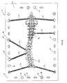
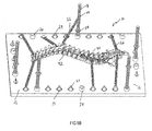
- a novel spinal surgery modeling system is provided with a stable platform 12 having multiple anchor attachment elements 14 attached at different locations along the platform perimeter 16.
- the attachment elements 14 can be uniformly positioned around the platform perimeter 16 or can be located in selected positions to accommodate specific user requirements.
- the platform 12 also is provided with multiple vertical supports 18, which are also located proximate to the perimeter 16 of the platform 12. The number of attachment elements 14 and vertical supports 18 can vary according to the specific need of the user and can be interchanged one for the other at any of the positions around the platform perimeter 16.
- Each of the vertical supports 18 includes a vertical support mounting base 20, which provides a stable foundation for a vertical support shaft 22.
- the vertical support shaft 22 is releasably attached to the vertical support base 20 so as to enable the selective positioning of each of the vertical support shafts 22 as needed around the platform perimeter 16.
- the vertical support shafts 22 are preferably threadably attached to their respective vertical support bases 20; however, it is within the inventor's conception that any known releasable attachment capable of providing a secure connection can be used, such as, for example, bayonet attachments, friction fit attachments, knob and groove connections, and the like.
- the anchor attachment elements 14 can include a tension member connector 24 configured to facilitate easy connection and disconnection of the anchor attachment elements 14 to at least one tension member 26.
- a tension member connector 24 configured to facilitate easy connection and disconnection of the anchor attachment elements 14 to at least one tension member 26.
- FIG's. 1, 2A-B, and 5A-B a preferred embodiment of the system 10 is provided with eyelet type tension member connectors 24. It is, however, with the inventor's conception that any suitable connector can be used that facilitates quick, easy connection and disconnection one or more tension members 26.
- the preferred tension members 26 can be provided as coiled springs having a first attaching member 28 and a second attaching member 30.
- the first and second attaching members 28, 30 can be securely attached to or integrally formed with the first and second opposing ends 32, 34 of the tension members 26.
- the attaching members 28, 30 in a preferred embodiment can be hooks, which can be easily connected and disconnect; however, as shown in FIG's. 4A-C,
- the tension members 26 can be provided as a set of differing coiled springs having closed attachment members, the coiled springs varying in length and strength so as to allow the user to select the degree of tension used at different points in the system 10.
- the vertical support shaft 22 can be provided as a threaded shaft having a threadably engaged tension member retainer 38 that can be adjusted in position along the length of the vertical support shaft 22 as desired.
- the tension member retainer 38 is sized and configured to selectively retain the attaching member 28 of a tension member 26 so as to provide an elevated anchoring contact for tension members 26 when desired.
- FIG's 1, 2B, and 5A-B show vertical support shafts 22 with tension members retainers positioned at varying elevations above the platform 12.
- Fig. 5A-B shows a model of a spinal column attached by tension members 26 to the platform 12, wherein some of the tension members 26 are connected to vertical support shafts 22 at elevated positions. As shown in Fig.
- the tension member first end 32 can be connected to the platform 12 by the releasable connection of a first attaching member 28 to an anchoring attachment elements 14 while the tension member second end 34 is attached to a model of a spine by releasable attachment of a second attaching member 30 to a position on the spinal column or alternatively to a position on the construct 40 being surgically inserted along the spinal column 42.
- a first attaching member 28 to an anchoring attachment elements 14
- the tension member second end 34 is attached to a model of a spine by releasable attachment of a second attaching member 30 to a position on the spinal column or alternatively to a position on the construct 40 being surgically inserted along the spinal column 42.
- the effect of attaching a model of a spinal column 42 to the platform 12 using various tension members 26 connected at different elevations to the anchoring attachment elements 14 or the vertical tensioner supports 18 is to produce a model of a spinal column the alignment of which may be contorted into an abnormal conformation, such as would be found in a patient suffering from scoliosis or other ailment.
- a spinal surgery model can be provided for use as a training device upon which surgeons can employ surgical methods and devices in a non-surgical environment.
- the use of the modeling system 10 can be repeated as necessary to ensure a good understanding of the surgical methods and devices used without the imposition of the conventionally high cost of using cadavers to attempt to achieve the same end result.
- system 10 can be configured to model the spinal column conformation of an actual patient scheduled for a future surgical procedure so that the modeling system 10 can be used by the surgeon as a tool to permit hands on rehearsal of the planned procedure without cost or potential harm to the patient. Used in this manner the system 10 can permit the surgeon to alter his surgery plan as he sees fit based upon the initial rehearsal session using the modeling system 10. Such rehearsal can involve using spinal instruments to implant spinal implants into the spine model as intended during surgery, to assess the effectiveness of the surgical plan.
- the hands on modeling system 10 can be used in close coordination with the data obtained by known methods for preparing plans for surgical procedures.
- Templates normally prepared in two dimensional models for surgery plans can be incorporated into the three dimensional model of the present modeling system 10 so as to provide a very close fit of the model to the actual anatomy and biomechanics of the patient. While the system preferably is intended to model surgical procedures, it can also be employed to provide a model test bed for new designs of surgical instruments and surgical implants.
- models of the spinal column 42 can be provided with the system 10 as part of a kit, which can include spinal models of different sizes for pediatric, adult, and geriatric patients. Additionally, models of spinal columns can be provided that reproduce different features of common abnormalities so as to provide a realistic model for use in surgical training or rehearsal, possibly to include use of spinal implants and instruments on the spinal model.
- the spinal surgery modeling system 10 disclosed herein can be electronically duplicated to provide a virtual surgery modeling system wherein the surgeon can train or rehearse surgical procedures using realistically modeled surgical instrument devices that transmit the surgeon's manipulations into a virtual surgical model which provides immediate visual and mechanical feedback to the user.
- Virtual reality systems well known in the art can be employed to achieve this aspect of the inventor's conception.
- visual feedback of a virtual reality embodiment of the modeling system 10 can be provided by producing an image on a screen or by transmitting an image to a visual presentation produced in headgear worn by a user.
- mechanical or tactile feedback can be provided to the user using servos to produce hand manipulation and simulated tension feedback as programmed into the automated embodiment.
- the materials used to construct the present invention are those which have sufficient strength and resiliency to support the forces that are imposed by the tension members 26, as well as the surgical manipulations of the model of the spinal column 42.
- the spinal surgery modeling system 10 as a kit for use in a surgical process, the kit including the system 10 as described herein, as well as at least one other surgical instrument or device.
- surgical instruments or surgical implants that can be included in such a kit included, for example, the devices disclosed in U.S. Patent 5,733,286 , U.S. Patent 5,683,392 , U.S. Published Application 2007/0093849 , U.S. Published Application 2007/0093817 , U.S. Published Application 2007/0213722 , U.S. Published Application 2007/0016197 , all of which are fully incorporated herein by reference.
- well known and conventionally used surgical instruments and implants can be included with system 10 to provide a kit.
- the kit can contain at least one anatomical model of a spinal column or a portion of a spinal column for use with the system 10.
Landscapes
- Engineering & Computer Science (AREA)
- Physics & Mathematics (AREA)
- General Physics & Mathematics (AREA)
- Mathematical Analysis (AREA)
- Mathematical Physics (AREA)
- Medicinal Chemistry (AREA)
- General Health & Medical Sciences (AREA)
- Algebra (AREA)
- Computational Mathematics (AREA)
- Chemical & Material Sciences (AREA)
- Health & Medical Sciences (AREA)
- Mathematical Optimization (AREA)
- Medical Informatics (AREA)
- Pure & Applied Mathematics (AREA)
- Business, Economics & Management (AREA)
- Educational Administration (AREA)
- Educational Technology (AREA)
- Theoretical Computer Science (AREA)
- Surgical Instruments (AREA)
- Prostheses (AREA)
Applications Claiming Priority (1)
| Application Number | Priority Date | Filing Date | Title |
|---|---|---|---|
| US98207907P | 2007-10-23 | 2007-10-23 |
Publications (2)
| Publication Number | Publication Date |
|---|---|
| EP2053580A1 true EP2053580A1 (de) | 2009-04-29 |
| EP2053580B1 EP2053580B1 (de) | 2012-08-15 |
Family
ID=40381609
Family Applications (1)
| Application Number | Title | Priority Date | Filing Date |
|---|---|---|---|
| EP08018561A Not-in-force EP2053580B1 (de) | 2007-10-23 | 2008-10-23 | Wirbelsäulenoperationsmodelliersystem |
Country Status (2)
| Country | Link |
|---|---|
| US (1) | US8113847B2 (de) |
| EP (1) | EP2053580B1 (de) |
Cited By (11)
| Publication number | Priority date | Publication date | Assignee | Title |
|---|---|---|---|---|
| US10318655B2 (en) | 2013-09-18 | 2019-06-11 | Medicrea International | Method making it possible to produce the ideal curvature of a rod of vertebral osteosynthesis material designed to support a patient's vertebral column |
| US10314657B2 (en) | 2013-10-18 | 2019-06-11 | Medicrea International | Methods, systems, and devices for designing and manufacturing a spinal rod |
| US10456211B2 (en) | 2015-11-04 | 2019-10-29 | Medicrea International | Methods and apparatus for spinal reconstructive surgery and measuring spinal length and intervertebral spacing, tension and rotation |
| US10918422B2 (en) | 2017-12-01 | 2021-02-16 | Medicrea International | Method and apparatus for inhibiting proximal junctional failure |
| US11185369B2 (en) | 2017-04-21 | 2021-11-30 | Medicrea Nternational | Systems, methods, and devices for developing patient-specific spinal treatments, operations, and procedures |
| US11612436B2 (en) | 2016-12-12 | 2023-03-28 | Medicrea International | Systems, methods, and devices for developing patient-specific medical treatments, operations, and procedures |
| US11769251B2 (en) | 2019-12-26 | 2023-09-26 | Medicrea International | Systems and methods for medical image analysis |
| US11877801B2 (en) | 2019-04-02 | 2024-01-23 | Medicrea International | Systems, methods, and devices for developing patient-specific spinal implants, treatments, operations, and/or procedures |
| US11925417B2 (en) | 2019-04-02 | 2024-03-12 | Medicrea International | Systems, methods, and devices for developing patient-specific spinal implants, treatments, operations, and/or procedures |
| US12274511B2 (en) | 2019-04-02 | 2025-04-15 | Medicrea International | Systems and methods for medical image analysis |
| US12564447B2 (en) | 2019-04-02 | 2026-03-03 | Medicrea International | Systems, methods, and devices for developing patient-specific spinal implants, treatments, operations, and/or procedures |
Families Citing this family (17)
| Publication number | Priority date | Publication date | Assignee | Title |
|---|---|---|---|---|
| US8403676B2 (en) * | 2006-05-19 | 2013-03-26 | Olympus Endo Technology America Inc. | Anatomical model |
| US9011158B2 (en) * | 2013-02-07 | 2015-04-21 | The Johns Hopkins University | Human surrogate neck model |
| AU2014201336B2 (en) | 2013-03-11 | 2018-04-19 | K2M, Inc. | Flexible Fastening System |
| US9501953B2 (en) * | 2013-03-15 | 2016-11-22 | Gaumard Scientific Company, Inc. | Birthing simulation devices, systems, and methods |
| US10438511B2 (en) * | 2013-11-11 | 2019-10-08 | K2M, Inc. | Growing spine model |
| US20160000514A1 (en) * | 2014-07-03 | 2016-01-07 | Alan Ellman | Surgical vision and sensor system |
| EP2975599B1 (de) | 2014-07-14 | 2017-10-18 | K2M, Inc. | Wachsendes wirbelsäulenmodell |
| US20160140879A1 (en) * | 2014-11-19 | 2016-05-19 | David Hananel | Anatomically correct movement or deformation of simulated bodily structures |
| US9965977B2 (en) * | 2014-12-31 | 2018-05-08 | Humanetics Innovative Solutions, Inc. | Adjustable lumbar spine assembly for crash test dummy |
| WO2018071514A1 (en) | 2016-10-11 | 2018-04-19 | K2M, Inc. | Spinal implant and methods of use thereof |
| US10102776B2 (en) * | 2016-11-17 | 2018-10-16 | Warsaw Orthopedic, Inc. | Simulation device and method for using same |
| EP3355215A1 (de) * | 2017-01-31 | 2018-08-01 | Medability GmbH | Medizinisches stimulationssystem, verfahren und verwendung |
| US10971037B2 (en) * | 2017-05-26 | 2021-04-06 | Iowa State University Research Foundation, Inc. | Synthetic knee joint apparatus and related educational methods for clinical knee joint examinations |
| US10529255B2 (en) | 2017-06-02 | 2020-01-07 | Synaptive Medical (Barbados) Inc. | Spinal training simulator |
| CN107895597B (zh) * | 2017-11-30 | 2021-11-23 | 吉林大学 | 一种参数化癌转移人体脊柱模型重建与分析系统 |
| US12499782B2 (en) * | 2020-12-18 | 2025-12-16 | Drake University | Tri spine model |
| CN116564158A (zh) * | 2023-06-05 | 2023-08-08 | 上海交通大学医学院附属瑞金医院卢湾分院 | 一种脊柱侧弯腰椎穿刺训练方法及系统 |
Citations (11)
| Publication number | Priority date | Publication date | Assignee | Title |
|---|---|---|---|---|
| US2197975A (en) * | 1938-03-21 | 1940-04-23 | James L Price | Anatomical demonstrating device |
| US5683392A (en) | 1995-10-17 | 1997-11-04 | Wright Medical Technology, Inc. | Multi-planar locking mechanism for bone fixation |
| US5733286A (en) | 1997-02-12 | 1998-03-31 | Third Millennium Engineering, Llc | Rod securing polyaxial locking screw and coupling element assembly |
| US5873732A (en) * | 1997-09-26 | 1999-02-23 | Hasson; Harrith M. | Apparatus for training for the performance of a medical procedure |
| WO2003049066A1 (en) * | 2001-12-03 | 2003-06-12 | Sdgi Holdings, Inc. | Demonstration devices for medical procedures |
| US20060085068A1 (en) * | 2004-10-18 | 2006-04-20 | Barry Richard J | Spine microsurgery techniques, training aids and implants |
| WO2006134146A1 (en) * | 2005-06-15 | 2006-12-21 | Oliver Browne-Wilkinson | Orthopaedic skeletal demonstration aids |
| US20070016197A1 (en) | 2005-05-23 | 2007-01-18 | Woods Richard W | Cross-connector assembly |
| US20070093817A1 (en) | 2005-09-29 | 2007-04-26 | Michael Barrus | Spinal fixation system having locking and unlocking devices for use with a multi-planar, taper lock screw |
| US20070093849A1 (en) | 2005-09-29 | 2007-04-26 | Jones Scott A | Single action anti-torque rod reducer |
| US20070213722A1 (en) | 2006-03-09 | 2007-09-13 | Jones Scott A | Dual action rod reducing and locking device and method |
Family Cites Families (11)
| Publication number | Priority date | Publication date | Assignee | Title |
|---|---|---|---|---|
| US2108229A (en) * | 1935-07-05 | 1938-02-15 | Martha M Metz | Anatomical skeleton |
| US2103021A (en) * | 1936-04-07 | 1937-12-21 | Salsman George Wesley | Chiropractic demonstrating device |
| US3020652A (en) * | 1960-10-25 | 1962-02-13 | Ferrari | Neurological manikin |
| US3513569A (en) * | 1967-12-29 | 1970-05-26 | Thorston D Herou | Vertebrae structure |
| US5882206A (en) * | 1995-03-29 | 1999-03-16 | Gillio; Robert G. | Virtual surgery system |
| IE20000748A1 (en) * | 1999-09-17 | 2001-04-04 | Markport Ltd | A short message gateway |
| US6582232B1 (en) * | 1999-12-02 | 2003-06-24 | Marshall James Ney | Pain management model |
| US6468087B2 (en) * | 2000-01-31 | 2002-10-22 | D. Barclay Slocum Trust Agreement | Apparatus for demonstrating a skeletal surgical technique |
| US7403883B2 (en) * | 2003-10-03 | 2008-07-22 | Medtronic, Inc. | Three-dimensional in-vitro spinal models and methods of analyzing substance distribution therein |
| US7909610B1 (en) * | 2006-12-21 | 2011-03-22 | Amato Craniofacial Engineering, LLC | Computer-aided system of orthopedic surgery |
| US7942676B2 (en) * | 2007-06-21 | 2011-05-17 | Charles Murdach | Human spine model |
-
2008
- 2008-10-18 US US12/253,965 patent/US8113847B2/en not_active Expired - Fee Related
- 2008-10-23 EP EP08018561A patent/EP2053580B1/de not_active Not-in-force
Patent Citations (11)
| Publication number | Priority date | Publication date | Assignee | Title |
|---|---|---|---|---|
| US2197975A (en) * | 1938-03-21 | 1940-04-23 | James L Price | Anatomical demonstrating device |
| US5683392A (en) | 1995-10-17 | 1997-11-04 | Wright Medical Technology, Inc. | Multi-planar locking mechanism for bone fixation |
| US5733286A (en) | 1997-02-12 | 1998-03-31 | Third Millennium Engineering, Llc | Rod securing polyaxial locking screw and coupling element assembly |
| US5873732A (en) * | 1997-09-26 | 1999-02-23 | Hasson; Harrith M. | Apparatus for training for the performance of a medical procedure |
| WO2003049066A1 (en) * | 2001-12-03 | 2003-06-12 | Sdgi Holdings, Inc. | Demonstration devices for medical procedures |
| US20060085068A1 (en) * | 2004-10-18 | 2006-04-20 | Barry Richard J | Spine microsurgery techniques, training aids and implants |
| US20070016197A1 (en) | 2005-05-23 | 2007-01-18 | Woods Richard W | Cross-connector assembly |
| WO2006134146A1 (en) * | 2005-06-15 | 2006-12-21 | Oliver Browne-Wilkinson | Orthopaedic skeletal demonstration aids |
| US20070093817A1 (en) | 2005-09-29 | 2007-04-26 | Michael Barrus | Spinal fixation system having locking and unlocking devices for use with a multi-planar, taper lock screw |
| US20070093849A1 (en) | 2005-09-29 | 2007-04-26 | Jones Scott A | Single action anti-torque rod reducer |
| US20070213722A1 (en) | 2006-03-09 | 2007-09-13 | Jones Scott A | Dual action rod reducing and locking device and method |
Non-Patent Citations (1)
| Title |
|---|
| ELAINE CHEN ET AL: "Force Feedback for Surgical Simulation", 1 March 1998, PROCEEDINGS OF THE IEEE, IEEE. NEW YORK, US, ISSN: 0018-9219, XP011043988 * |
Cited By (27)
| Publication number | Priority date | Publication date | Assignee | Title |
|---|---|---|---|---|
| US10970426B2 (en) | 2013-09-18 | 2021-04-06 | Medicrea International SA | Methods, systems, and devices for designing and manufacturing a spinal rod |
| US12417323B2 (en) | 2013-09-18 | 2025-09-16 | Medicrea International | Method of making it possible to produce and ideal curvature of a rod of vertebral osteosynthesis material designed to support a patient's vertebral column |
| US12019955B2 (en) | 2013-09-18 | 2024-06-25 | Medicrea International | Method making it possible to produce the ideal curvature of a rod of vertebral osteosynthesis material designed to support a patient's vertebral column |
| US10318655B2 (en) | 2013-09-18 | 2019-06-11 | Medicrea International | Method making it possible to produce the ideal curvature of a rod of vertebral osteosynthesis material designed to support a patient's vertebral column |
| US11918295B2 (en) | 2013-10-18 | 2024-03-05 | Medicrea International | Methods, systems, and devices for designing and manufacturing a spinal rod |
| US10413365B1 (en) | 2013-10-18 | 2019-09-17 | Medicrea International | Methods, systems, and devices for designing and manufacturing a spinal rod |
| US10433913B2 (en) | 2013-10-18 | 2019-10-08 | Medicrea International | Methods, systems, and devices for designing and manufacturing a spinal rod |
| US10441363B1 (en) | 2013-10-18 | 2019-10-15 | Medicrea International | Methods, systems, and devices for designing and manufacturing a spinal rod |
| US10314657B2 (en) | 2013-10-18 | 2019-06-11 | Medicrea International | Methods, systems, and devices for designing and manufacturing a spinal rod |
| US12257000B2 (en) | 2013-10-18 | 2025-03-25 | Medicrea International | Methods, systems, and devices for designing and manufacturing a spinal rod |
| US10426553B2 (en) | 2013-10-18 | 2019-10-01 | Medicrea International | Methods, systems, and devices for designing and manufacturing a spinal rod |
| US10973582B2 (en) | 2013-10-18 | 2021-04-13 | Medicrea International | Methods, systems, and devices for designing and manufacturing a spinal rod |
| US10433912B1 (en) | 2013-10-18 | 2019-10-08 | Medicrea International | Methods, systems, and devices for designing and manufacturing a spinal rod |
| US11197718B2 (en) | 2013-10-18 | 2021-12-14 | Medicrea Iniernational | Methods, systems, and devices for designing and manufacturing a spinal rod |
| US11197719B2 (en) | 2013-10-18 | 2021-12-14 | Medicrea International | Methods, systems, and devices for designing and manufacturing a spinal rod |
| US10420615B1 (en) | 2013-10-18 | 2019-09-24 | Medicrea International | Methods, systems, and devices for designing and manufacturing a spinal rod |
| US10456211B2 (en) | 2015-11-04 | 2019-10-29 | Medicrea International | Methods and apparatus for spinal reconstructive surgery and measuring spinal length and intervertebral spacing, tension and rotation |
| US11612436B2 (en) | 2016-12-12 | 2023-03-28 | Medicrea International | Systems, methods, and devices for developing patient-specific medical treatments, operations, and procedures |
| US12178516B2 (en) | 2016-12-12 | 2024-12-31 | Medicrea International | Systems, methods, and devices for developing patient-specific medical treatments, operations, and procedures |
| US11185369B2 (en) | 2017-04-21 | 2021-11-30 | Medicrea Nternational | Systems, methods, and devices for developing patient-specific spinal treatments, operations, and procedures |
| US10918422B2 (en) | 2017-12-01 | 2021-02-16 | Medicrea International | Method and apparatus for inhibiting proximal junctional failure |
| US11877801B2 (en) | 2019-04-02 | 2024-01-23 | Medicrea International | Systems, methods, and devices for developing patient-specific spinal implants, treatments, operations, and/or procedures |
| US11925417B2 (en) | 2019-04-02 | 2024-03-12 | Medicrea International | Systems, methods, and devices for developing patient-specific spinal implants, treatments, operations, and/or procedures |
| US12251165B2 (en) | 2019-04-02 | 2025-03-18 | Medicrea International | Systems, methods, and devices for developing patient-specific spinal implants, treatments, operations, and/or procedures |
| US12274511B2 (en) | 2019-04-02 | 2025-04-15 | Medicrea International | Systems and methods for medical image analysis |
| US12564447B2 (en) | 2019-04-02 | 2026-03-03 | Medicrea International | Systems, methods, and devices for developing patient-specific spinal implants, treatments, operations, and/or procedures |
| US11769251B2 (en) | 2019-12-26 | 2023-09-26 | Medicrea International | Systems and methods for medical image analysis |
Also Published As
| Publication number | Publication date |
|---|---|
| US8113847B2 (en) | 2012-02-14 |
| EP2053580B1 (de) | 2012-08-15 |
| US20090162821A1 (en) | 2009-06-25 |
Similar Documents
| Publication | Publication Date | Title |
|---|---|---|
| EP2053580B1 (de) | Wirbelsäulenoperationsmodelliersystem | |
| EP2975599B1 (de) | Wachsendes wirbelsäulenmodell | |
| US20080138781A1 (en) | Surgical training model and method for use in facilitating training of a surgical procedure | |
| CN104363826B (zh) | 患者匹配的外科导向件及其使用方法 | |
| US20100217336A1 (en) | Computerized Planning Tool For Spine Surgery and Method and Device for Creating a Customized Guide for Implantations | |
| US8439688B2 (en) | Orthopedic procedures training simulator | |
| JP2005512131A (ja) | 医療処置の実演装置 | |
| WO2008027549A2 (en) | Computerized planning tool surgery | |
| US20070093998A1 (en) | Method for biomehcanically simulating of a set of osseous joints | |
| CA2923190C (en) | Manipulative treatment training system and method, and mannequin therefor | |
| US20140370475A1 (en) | Simulation system and methods for surgical training | |
| US10438511B2 (en) | Growing spine model | |
| US20240363028A1 (en) | Surgical training model | |
| CN116386409A (zh) | 颈椎微小错位仿真正骨训练装置和方法 | |
| Rashim et al. | Increasing the safety of surgical treatment for complex Cranio-vertebral anomalies using customized 3D printed models | |
| EP3306594B1 (de) | In-situ-trainingsvorrichtung, -verfahren und -system | |
| CN118942317A (zh) | 一种脊柱内镜手术训练专用高精度仿生腰椎模型 | |
| JP2002510069A (ja) | 特に脊柱の整形外科医のトレーニングのための解剖学的構造 | |
| Soffar et al. | Virtual reality simulation for orthopedic surgical training: A narrative review of current evidence and educational impact | |
| Moafimadani et al. | Haptic training simulator for pedicle screw insertion in scoliosis surgery | |
| AU2023202629B2 (en) | Surgical Training Model | |
| EP3580739B1 (de) | System und verfahren zur validierung und zum training operativer eingriffe in der human- und veterinärmedizin | |
| Moore | Understanding Scoliosis: What Caregivers and Patients Need to Know | |
| DE102017202164A1 (de) | System und Verfahren zur Validierung und zum Training operativer Eingriffe in der Human- und Veterinärmedizin | |
| Blair-Pattison | Development and characterization of a synthetic bone analogue for surgical training |
Legal Events
| Date | Code | Title | Description |
|---|---|---|---|
| PUAI | Public reference made under article 153(3) epc to a published international application that has entered the european phase |
Free format text: ORIGINAL CODE: 0009012 |
|
| AK | Designated contracting states |
Kind code of ref document: A1 Designated state(s): AT BE BG CH CY CZ DE DK EE ES FI FR GB GR HR HU IE IS IT LI LT LU LV MC MT NL NO PL PT RO SE SI SK TR |
|
| AX | Request for extension of the european patent |
Extension state: AL BA MK RS |
|
| 17P | Request for examination filed |
Effective date: 20091029 |
|
| 17Q | First examination report despatched |
Effective date: 20091123 |
|
| AKX | Designation fees paid |
Designated state(s): DE FR GB |
|
| GRAP | Despatch of communication of intention to grant a patent |
Free format text: ORIGINAL CODE: EPIDOSNIGR1 |
|
| GRAS | Grant fee paid |
Free format text: ORIGINAL CODE: EPIDOSNIGR3 |
|
| GRAA | (expected) grant |
Free format text: ORIGINAL CODE: 0009210 |
|
| AK | Designated contracting states |
Kind code of ref document: B1 Designated state(s): DE FR GB |
|
| REG | Reference to a national code |
Ref country code: GB Ref legal event code: FG4D |
|
| REG | Reference to a national code |
Ref country code: DE Ref legal event code: R096 Ref document number: 602008017951 Country of ref document: DE Effective date: 20121018 |
|
| PLBE | No opposition filed within time limit |
Free format text: ORIGINAL CODE: 0009261 |
|
| STAA | Information on the status of an ep patent application or granted ep patent |
Free format text: STATUS: NO OPPOSITION FILED WITHIN TIME LIMIT |
|
| 26N | No opposition filed |
Effective date: 20130516 |
|
| REG | Reference to a national code |
Ref country code: DE Ref legal event code: R097 Ref document number: 602008017951 Country of ref document: DE Effective date: 20130516 |
|
| REG | Reference to a national code |
Ref country code: FR Ref legal event code: PLFP Year of fee payment: 8 |
|
| REG | Reference to a national code |
Ref country code: FR Ref legal event code: PLFP Year of fee payment: 9 |
|
| REG | Reference to a national code |
Ref country code: FR Ref legal event code: PLFP Year of fee payment: 10 |
|
| REG | Reference to a national code |
Ref country code: FR Ref legal event code: PLFP Year of fee payment: 11 |
|
| PGFP | Annual fee paid to national office [announced via postgrant information from national office to epo] |
Ref country code: FR Payment date: 20190913 Year of fee payment: 12 |
|
| PGFP | Annual fee paid to national office [announced via postgrant information from national office to epo] |
Ref country code: DE Payment date: 20191008 Year of fee payment: 12 |
|
| PGFP | Annual fee paid to national office [announced via postgrant information from national office to epo] |
Ref country code: GB Payment date: 20191024 Year of fee payment: 12 |
|
| REG | Reference to a national code |
Ref country code: DE Ref legal event code: R119 Ref document number: 602008017951 Country of ref document: DE |
|
| GBPC | Gb: european patent ceased through non-payment of renewal fee |
Effective date: 20201023 |
|
| PG25 | Lapsed in a contracting state [announced via postgrant information from national office to epo] |
Ref country code: DE Free format text: LAPSE BECAUSE OF NON-PAYMENT OF DUE FEES Effective date: 20210501 Ref country code: FR Free format text: LAPSE BECAUSE OF NON-PAYMENT OF DUE FEES Effective date: 20201031 |
|
| PG25 | Lapsed in a contracting state [announced via postgrant information from national office to epo] |
Ref country code: GB Free format text: LAPSE BECAUSE OF NON-PAYMENT OF DUE FEES Effective date: 20201023 |