EP2053716A2 - Verfahren zur Detektion von Wechselstrom-Serienlichtbogenfehlern - Google Patents
Verfahren zur Detektion von Wechselstrom-Serienlichtbogenfehlern Download PDFInfo
- Publication number
- EP2053716A2 EP2053716A2 EP08253137A EP08253137A EP2053716A2 EP 2053716 A2 EP2053716 A2 EP 2053716A2 EP 08253137 A EP08253137 A EP 08253137A EP 08253137 A EP08253137 A EP 08253137A EP 2053716 A2 EP2053716 A2 EP 2053716A2
- Authority
- EP
- European Patent Office
- Prior art keywords
- current
- level
- positive
- absolute
- establish
- Prior art date
- Legal status (The legal status is an assumption and is not a legal conclusion. Google has not performed a legal analysis and makes no representation as to the accuracy of the status listed.)
- Granted
Links
Images

Classifications
-
- H—ELECTRICITY
- H02—GENERATION; CONVERSION OR DISTRIBUTION OF ELECTRIC POWER
- H02H—EMERGENCY PROTECTIVE CIRCUIT ARRANGEMENTS
- H02H1/00—Details of emergency protective circuit arrangements
- H02H1/0007—Details of emergency protective circuit arrangements concerning the detecting means
- H02H1/0015—Using arc detectors
Definitions
- the invention relates to identification of electrical arc faults and, more particularly, to methodology for identifying the occurrence of alternating current (AC) arcing events.
- AC alternating current
- Arcing faults mainly occur in one of two ways, series arcing faults or parallel arcing faults.
- a series arc can occur due to an unintentional break in an electrical system conduction path for its load.
- a series arc is load limited because the arc current cannot be greater than the current that the conduction path provides to its load.
- Conduction path current that experiences series arcing has a lower root mean square (rms) value than current without such series arcing due to extinction and re-ignition.
- Parallel arcing faults either occur because of an electrical system conduction path that experiences a short circuit or a ground fault.
- the only limit for the current flow of a parallel arc is due to the electrical system impedance and the impedance of the fault itself.
- the rms current value for parallel arc faults may be considerably less than that of a solid fault so that ordinary circuit breaker systems may not detect such faults before they create a fire.
- Such electrical arcing may be inherently low impedance and occur infrequently. Such infrequent occurrence may prevent a thermal circuit breaker from reaching its predetermined temperature trip level or a solid-state power controller (SSPC) from reaching its predetermined energy trip rating.
- SSPC solid-state power controller
- conventional thermal circuit breakers and SSPCs typically do not trip when such electrical arcing occurs, even though it is desirable to detect electrical arc events for purposes such as identifying an electrical problem and preventing the problem from causing serious damage or hazards.
- Electrical arc detection hardware is available for electrical arc detection. Such hardware may couple to a thermal circuit breaker to detect an AC electrical arc and initiate a trip of the breaker. Likewise, such hardware may couple to a SSPC to detect an AC electric arc and initiate a trip of the SSPC. However, such electrical arc detection increases the size, weight and cost of the electrical system.
- EP 1804355 describes one effective solution for detecting electrical arc faults of both the series and parallel type that is suitable for incorporating into an SSPC with no additional hardware.
- Such electrical arc fault detection solutions typically compare a sample of the current with a previous sample to determine if arcing differences and characteristics exist. For maximum response, the comparison is usually on a half AC cycle basis.
- Certain AC loads typically those that comprise electrical rectification, switching, and other nonlinear functions may cause a direct current (DC) offset in the load current.
- a small DC offset in the AC load current is insignificant with respect to the overall load at the power source level, but it may be significant at a lower distribution level.
- the invention generally comprises a method of detecting and indicating a presence of alternating current (AC) series arc fault events in current supplied by an AC electrical power source to an electrical load for the power source, comprising the steps of: measuring positive and negative current through the load over a first sample cycle of the AC power to establish first measured positive and first measured negative current levels; determining the absolute value of the first measured positive and first measured negative current levels to establish a first absolute positive current level and a first absolute negative current level; adding the first absolute positive current level and the first absolute negative current level to establish a first sum current level; measuring positive and negative current through the load over a second sample cycle of the AC power staggered the first sample cycle to establish second measured positive and second measured negative current levels; determining the absolute value of the second measured positive and second measured negative current levels to establish a second absolute positive current level and a second absolute negative current level; adding the second absolute positive current level and the second absolute negative current level to establish a second sum current level; subtracting the second sum current level from the first sum current level to establish a current difference level;
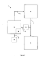
- FIG. 1 is a high-level schematic diagram of an alternating current (AC) electrical system 2 that is configurable for a possible embodiment of the invention.
- the electrical system 2 comprises an AC source 4 that powers an AC electrical load 6 by means of an AC power bus 8. Any sort of break or loose connection between the AC source 4 and the AC power bus 8, between the AC load 6 and the AC power bus 8 or within the AC power bus 8 itself may result in one or more AC series arc fault events.
- An electrical system control unit 10 that controls distribution of power from the AC source 4 by means of a control bus 12 may measure current in the AC power bus 8 to detect arc fault events between the AC source 4 and the electrical load 6, such as by means of an AC bus current signal generated by a current sensor 14 that it receives on a current signal feedback line 16.
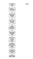
- Figure 3 is a flow chart that represents a method of detecting and indicating a presence of alternating current (AC) series arc fault (AF) events in the electrical system 2 according to a possible embodiment of the invention.
- This process starts with the system control unit 10 measuring the AC positive and negative current through the electrical load 6 over a first sample cycle of the AC power by means of the AC bus current signal generated by the current sensor 14 to establish first measured positive and first measured negative current levels.
- the system control unit 10 determines the absolute value of the first measured positive and first measured negative current levels to establish a first absolute positive current level and a first absolute negative current level.
- the system control unit 10 then adds the first absolute positive current level and the first absolute negative current level to establish a first sum current level.
- the system control unit 10 measures the AC positive and negative current through the electrical load 6 over a second sample cycle of the AC power staggered from the first sample cycle, by means of the AC bus current signal generated by the current sensor 14 to establish second measured positive and second measured negative current levels.
- the second sample cycle may have a one half AC cycle or a full AC cycle stagger from the first sample cycle.
- the system control unit 10 determines the absolute value of the second measured positive and second measured negative current levels to establish a second absolute positive current level and a second absolute negative current level.
- the system control unit 10 then adds the second absolute positive current level and the second absolute negative current level to establish a second sum current level.
- the system control unit 10 then subtracts the second sum current level from the first sum current level to establish a current difference level.
- the system control unit 10 then indicates a series arc fault event if the current difference level exceeds a predetermined threshold level.
- the system control unit 10 may indicate such a series arc fault by means of an arc fault signal that it generates on an arc fault signal line 18.
- An arc fault indicator 20 may receive the arc fault signal on the arc fault signal line 18 to display series arc fault events.
- the system control unit 10 then repeats this series arc fault detection and indication process with additional first and second samples as hereinbefore described.
- the system control unit 10 may also alter the distribution of power from the AC source 4 by means of the control bus 12 in response to such series arc fault events, such as by interrupting power to the electrical load 6 by means of the AC power bus 8. Furthermore, the system control unit 10 may delay series arc fault indication or protection until a predetermined number of such series arc fault events, such as five consecutive events, have occurred within a predetermined period.
- the process incorporates a rolling sample technique that cancels out the effective DC offset current.
- the technique combines the current positive half cycle and current negative half cycle current samples and compares them with the combination of the previous negative half cycle and the current positive half cycle.
- the next sample combines the next positive half cycle and negative half cycle current samples and compares them with the combination of the current negative half cycle and the current positive half cycle.
- the rolling samples continue on half cycle after half cycle.
- the process may evaluate a full AC cycle against the previous full AC cycle.
- the system control unit 10 may comprise a data processing system 22 for implementing the hereinbefore described process.
- Figure 3 is a high-level schematic diagram of a data processing system 22 for implementing the hereinbefore described process for detecting and indicating series AC arc fault events.
- the data processing system 22 may comprise a central processing unit (CPU) 24 coupled to a memory unit 26 by way of a two-way data bus 28.
- CPU central processing unit
- the memory unit 26 may comprise any sort of computer or CPU-readable media for storing instructions for carrying out the hereinbefore described process for detecting and indicating series AC arc fault events, such as read-only memory (ROM), random-access memory (RAM), electrically erasable programmable read-only memory (EEPROM) or flash memory, optical media such as any sort of optical data storage disc or magnetic media such as any sort of magnetic storage disc.
- the data processing system 22 may comprise an application-specific integrated circuit (ASIC) that comprises such CPU 24 and memory unit 26 functionality.
- ASIC application-specific integrated circuit
- the CPU 24 executes the hereinbefore described process for detecting and indicating series AC arc fault events in response to an AC bus current signal generated by the current sensor 14 to generate the arc fault signal on the arc fault signal line 18 whenever the current difference level exceeds the predetermined threshold level.
Landscapes
- Emergency Protection Circuit Devices (AREA)
- Testing Of Short-Circuits, Discontinuities, Leakage, Or Incorrect Line Connections (AREA)
Applications Claiming Priority (1)
| Application Number | Priority Date | Filing Date | Title |
|---|---|---|---|
| US11/876,004 US7633729B2 (en) | 2007-10-22 | 2007-10-22 | Alternating current series arc fault detection method |
Publications (3)
| Publication Number | Publication Date |
|---|---|
| EP2053716A2 true EP2053716A2 (de) | 2009-04-29 |
| EP2053716A3 EP2053716A3 (de) | 2012-01-25 |
| EP2053716B1 EP2053716B1 (de) | 2016-03-23 |
Family
ID=40263318
Family Applications (1)
| Application Number | Title | Priority Date | Filing Date |
|---|---|---|---|
| EP08253137.7A Active EP2053716B1 (de) | 2007-10-22 | 2008-09-25 | Verfahren zur Detektion von Wechselstrom-Serienlichtbogenfehlern |
Country Status (2)
| Country | Link |
|---|---|
| US (1) | US7633729B2 (de) |
| EP (1) | EP2053716B1 (de) |
Families Citing this family (18)
| Publication number | Priority date | Publication date | Assignee | Title |
|---|---|---|---|---|
| US7003435B2 (en) | 2002-10-03 | 2006-02-21 | Leviton Manufacturing Co., Inc. | Arc fault detector with circuit interrupter |
| FI120565B (fi) * | 2007-12-20 | 2009-11-30 | Abb Oy | Menetelmä ja laitteisto maasulun havaitsemiseen |
| CN101910856B (zh) | 2008-01-29 | 2014-06-18 | 立维腾制造有限公司 | 自测试故障电路中断器装置和方法 |
| US8320090B2 (en) | 2010-06-08 | 2012-11-27 | Hamilton Sundstrand Corporation | SSPC for parallel arc fault detection in DC power system |
| US8599523B1 (en) | 2011-07-29 | 2013-12-03 | Leviton Manufacturing Company, Inc. | Arc fault circuit interrupter |
| US20130262003A1 (en) * | 2012-03-27 | 2013-10-03 | Hamilton Sundstrand Corporation | Current measurement and comparing assembly for a power distribution system and method for measuring and comparing current |
| US9989138B2 (en) | 2012-04-26 | 2018-06-05 | Hamilton Sundstrand Corporation | Integrated drive generator having a variable input speed and constant output frequency and method of driving |
| CN102721896B (zh) * | 2012-07-05 | 2015-11-18 | 天津市鸿远电气设备有限公司 | 故障电弧检测方法 |
| RU2571513C2 (ru) * | 2013-04-22 | 2015-12-20 | Игорь Сергеевич КОРОЛЕВ | Способ предупреждения пожара от искрения в электрической сети или электроустановке и устройство для его осуществления |
| US9366716B2 (en) | 2013-05-23 | 2016-06-14 | Pentair Thermal Management Llc | Sub-harmonic arc fault detection system and method |
| US9366713B2 (en) | 2013-05-23 | 2016-06-14 | Pentair Thermal Management Llc | Arc fault detection system and method |
| US9759758B2 (en) | 2014-04-25 | 2017-09-12 | Leviton Manufacturing Co., Inc. | Ground fault detector |
| EP3262428A1 (de) * | 2015-02-23 | 2018-01-03 | GE Aviation Systems LLC | Verfahren und vorrichtung für ein stromfehlerdetektionssystem für ein kabel |
| DE102016209445B4 (de) * | 2016-05-31 | 2021-06-10 | Siemens Aktiengesellschaft | Störlichtbogenerkennungseinheit |
| RU2650105C2 (ru) * | 2016-09-30 | 2018-04-09 | ФЕДЕРАЛЬНОЕ ГОСУДАРСТВЕННОЕ КАЗЕННОЕ ВОЕННОЕ ОБРАЗОВАТЕЛЬНОЕ УЧРЕЖДЕНИЕ ВЫСШЕГО ОБРАЗОВАНИЯ "Военная академия Ракетных войск стратегического назначения имени Петра Великого" МИНИСТЕРСТВА ОБОРОНЫ РОССИЙСКОЙ ФЕДЕРАЦИИ | Способ предупреждения происшествия при неисправности в электрической сети постоянного и переменного тока и устройство для его осуществления |
| CN108132413B (zh) * | 2016-11-30 | 2021-06-18 | 上海航空电器有限公司 | 一种交流故障电弧的检测方法 |
| WO2018217883A2 (en) | 2017-05-23 | 2018-11-29 | Pass & Seymour, Inc. | Arc fault circuit interrupter |
| RU2700659C2 (ru) * | 2017-12-13 | 2019-09-18 | Федеральное государственное казенное военное образовательное учреждение высшего образования "Военная академия Ракетных войск стратегического назначения имени Петра Великого" МО РФ | Способ определения места искрения в электрической сети и устройство для его осуществления |
Citations (2)
| Publication number | Priority date | Publication date | Assignee | Title |
|---|---|---|---|---|
| EP0639879A2 (de) | 1993-08-20 | 1995-02-22 | Eaton Corporation | Lichtbogenerfassung über die Stromänderung |
| EP1804355A2 (de) | 2005-12-09 | 2007-07-04 | Hamilton Sundstrand Corporation | Detektion von und Schutz vor AC Lichtbogenfehlern |
Family Cites Families (4)
| Publication number | Priority date | Publication date | Assignee | Title |
|---|---|---|---|---|
| US5839092A (en) * | 1997-03-26 | 1998-11-17 | Square D Company | Arcing fault detection system using fluctuations in current peaks and waveforms |
| US6577138B2 (en) * | 2001-08-24 | 2003-06-10 | Eaton Corporation | Apparatus for detecting arcing and overcurrents in dc electrical systems subject to cyclic disturbances |
| US7349188B2 (en) * | 2005-06-06 | 2008-03-25 | Eaton Corporation | Arc fault detector responsive to patterns in interval to interval change in integrated sensed current values |
| US7359168B2 (en) * | 2005-10-18 | 2008-04-15 | Eaton Corporation | Arc fault circuit interrupter and method for disabling series arc protection during current transients |
-
2007
- 2007-10-22 US US11/876,004 patent/US7633729B2/en active Active
-
2008
- 2008-09-25 EP EP08253137.7A patent/EP2053716B1/de active Active
Patent Citations (2)
| Publication number | Priority date | Publication date | Assignee | Title |
|---|---|---|---|---|
| EP0639879A2 (de) | 1993-08-20 | 1995-02-22 | Eaton Corporation | Lichtbogenerfassung über die Stromänderung |
| EP1804355A2 (de) | 2005-12-09 | 2007-07-04 | Hamilton Sundstrand Corporation | Detektion von und Schutz vor AC Lichtbogenfehlern |
Also Published As
| Publication number | Publication date |
|---|---|
| EP2053716A3 (de) | 2012-01-25 |
| US20090103216A1 (en) | 2009-04-23 |
| US7633729B2 (en) | 2009-12-15 |
| EP2053716B1 (de) | 2016-03-23 |
Similar Documents
| Publication | Publication Date | Title |
|---|---|---|
| EP2053716B1 (de) | Verfahren zur Detektion von Wechselstrom-Serienlichtbogenfehlern | |
| US7796366B2 (en) | AC arc fault detection and protection | |
| EP2115844B1 (de) | Bogenfehler-unterbrecherschalter und verfahren zur parallel-bogenfehlerdetektion | |
| US8059378B2 (en) | Methods of improving the lightning immunity for an SSPC based aircraft electric power distribution system | |
| JP5485607B2 (ja) | 回路遮断器及び、回路遮断器によりアークフラッシュを検出する方法 | |
| US10732223B2 (en) | Circuit breaker health monitoring | |
| EP3120433B1 (de) | Verfahren und vorrichtung zum schutz von gleichstromverteilungssystemen | |
| EP2728691B1 (de) | Schaltung zur Fehlerstromermittlung | |
| US9618586B2 (en) | Method and device for detection of a fault in a protected unit | |
| US8659856B2 (en) | DC arc fault detection and protection | |
| CA2910749C (en) | Method of tripping a circuit interrupter in a back fed configuration | |
| US20090257156A1 (en) | Method of setting a ground fault trip function for a trip unit and a trip unit having a defined trip function for ground fault protection | |
| JP6509029B2 (ja) | 分電盤 | |
| US20180034260A1 (en) | Power distribution system for connection to an ac voltage network | |
| JP2016163523A (ja) | 分離器、及び分離方法 | |
| KR101984103B1 (ko) | 디지털 계전기 | |
| US12153079B2 (en) | Identifying conductor breaks by detecting series arcing | |
| JP7506240B1 (ja) | 保護継電システム、解列判定装置、解列判定方法、及びプログラム | |
| KR20250055854A (ko) | 회로 차단기의 회로 차단 시스템 | |
| JP2024072728A (ja) | 逆電力遮断継電器及び逆電力遮断継電器における逆電力遮断方法 | |
| Apostolov | Improving power quality by optimizing the protection of distribution systems | |
| JP2003134662A (ja) | 調相設備の保護装置 | |
| JP2020508445A (ja) | 遮断器 | |
| KR20090109494A (ko) | 접지 장애 트립 함수 설정 방법 | |
| JP2014232655A (ja) | 受変電設備のcrサプレッサ用抵抗器不良検出装置 |
Legal Events
| Date | Code | Title | Description |
|---|---|---|---|
| PUAI | Public reference made under article 153(3) epc to a published international application that has entered the european phase |
Free format text: ORIGINAL CODE: 0009012 |
|
| AK | Designated contracting states |
Kind code of ref document: A2 Designated state(s): AT BE BG CH CY CZ DE DK EE ES FI FR GB GR HR HU IE IS IT LI LT LU LV MC MT NL NO PL PT RO SE SI SK TR |
|
| AX | Request for extension of the european patent |
Extension state: AL BA MK RS |
|
| PUAL | Search report despatched |
Free format text: ORIGINAL CODE: 0009013 |
|
| AK | Designated contracting states |
Kind code of ref document: A3 Designated state(s): AT BE BG CH CY CZ DE DK EE ES FI FR GB GR HR HU IE IS IT LI LT LU LV MC MT NL NO PL PT RO SE SI SK TR |
|
| AX | Request for extension of the european patent |
Extension state: AL BA MK RS |
|
| RIC1 | Information provided on ipc code assigned before grant |
Ipc: H02H 1/00 20060101AFI20111221BHEP |
|
| 17P | Request for examination filed |
Effective date: 20120725 |
|
| AKX | Designation fees paid |
Designated state(s): FR GB |
|
| REG | Reference to a national code |
Ref country code: DE Ref legal event code: R108 |
|
| REG | Reference to a national code |
Ref country code: DE Ref legal event code: R108 Effective date: 20121004 |
|
| 17Q | First examination report despatched |
Effective date: 20121205 |
|
| GRAP | Despatch of communication of intention to grant a patent |
Free format text: ORIGINAL CODE: EPIDOSNIGR1 |
|
| INTG | Intention to grant announced |
Effective date: 20151006 |
|
| GRAS | Grant fee paid |
Free format text: ORIGINAL CODE: EPIDOSNIGR3 |
|
| GRAA | (expected) grant |
Free format text: ORIGINAL CODE: 0009210 |
|
| AK | Designated contracting states |
Kind code of ref document: B1 Designated state(s): FR GB |
|
| REG | Reference to a national code |
Ref country code: GB Ref legal event code: FG4D |
|
| REG | Reference to a national code |
Ref country code: FR Ref legal event code: PLFP Year of fee payment: 9 |
|
| PLBE | No opposition filed within time limit |
Free format text: ORIGINAL CODE: 0009261 |
|
| STAA | Information on the status of an ep patent application or granted ep patent |
Free format text: STATUS: NO OPPOSITION FILED WITHIN TIME LIMIT |
|
| 26N | No opposition filed |
Effective date: 20170102 |
|
| REG | Reference to a national code |
Ref country code: FR Ref legal event code: PLFP Year of fee payment: 10 |
|
| REG | Reference to a national code |
Ref country code: FR Ref legal event code: PLFP Year of fee payment: 11 |
|
| P01 | Opt-out of the competence of the unified patent court (upc) registered |
Effective date: 20230522 |
|
| PGFP | Annual fee paid to national office [announced via postgrant information from national office to epo] |
Ref country code: GB Payment date: 20250822 Year of fee payment: 18 |
|
| PGFP | Annual fee paid to national office [announced via postgrant information from national office to epo] |
Ref country code: FR Payment date: 20250820 Year of fee payment: 18 |