EP2054252B1 - Véhicule automobile avec des vitres latérales arrière - Google Patents
Véhicule automobile avec des vitres latérales arrière Download PDFInfo
- Publication number
- EP2054252B1 EP2054252B1 EP08715817A EP08715817A EP2054252B1 EP 2054252 B1 EP2054252 B1 EP 2054252B1 EP 08715817 A EP08715817 A EP 08715817A EP 08715817 A EP08715817 A EP 08715817A EP 2054252 B1 EP2054252 B1 EP 2054252B1
- Authority
- EP
- European Patent Office
- Prior art keywords
- side window
- rear side
- motor vehicle
- fastening film
- vehicle according
- Prior art date
- Legal status (The legal status is an assumption and is not a legal conclusion. Google has not performed a legal analysis and makes no representation as to the accuracy of the status listed.)
- Active
Links
Images



Classifications
-
- B—PERFORMING OPERATIONS; TRANSPORTING
- B60—VEHICLES IN GENERAL
- B60J—WINDOWS, WINDSCREENS, NON-FIXED ROOFS, DOORS, OR SIMILAR DEVICES FOR VEHICLES; REMOVABLE EXTERNAL PROTECTIVE COVERINGS SPECIALLY ADAPTED FOR VEHICLES
- B60J1/00—Windows; Windscreens; Accessories therefor
- B60J1/08—Windows; Windscreens; Accessories therefor arranged at vehicle sides
- B60J1/12—Windows; Windscreens; Accessories therefor arranged at vehicle sides adjustable
- B60J1/16—Windows; Windscreens; Accessories therefor arranged at vehicle sides adjustable slidable
- B60J1/17—Windows; Windscreens; Accessories therefor arranged at vehicle sides adjustable slidable vertically
Definitions
- the invention relates to a motor vehicle with rear side windows according to the preamble of claim 1.
- a motor vehicle is made DE 10 2004 063 513 known.
- each side of the body in the respective side wall only one door opening for a respective side door.
- the respective side door has a front side window, which are retractable via actuators in a cavity of a door body from an extended position to a retracted position and back.
- the front side window is framelessly attached to the door body.
- a rear side window is provided, which can be moved into a cavity of the body section via an actuating device from an extended position into a retracted position located in the cavity.
- a web is arranged, which serves for guiding and sealing the front pane and for holding and sealing the rear side window.
- the rear side window has a lower, non-visible portion, which is constantly in the cavity of the body portion.
- the rear side window On the lower, not visible edge on a through opening, in which the rear side window is connected via a screw connection with the actuating device.
- the actuator is attached to an inner wall of the cavity of the body portion for transmitting forces.
- the object of the invention is to provide a motor vehicle in which a rear side window has an improved structure.
- rear side windows are formed on both sides of the body, each adjacent to front, frameless side windows.
- the respective rear side window has a guide web on a front edge.
- the guide bar abuts a rear edge of a front side window when the front side window and the rear side window are in an extended position.
- the respective rear side window has a visible area in the extended position, while an invisible area of the rear side window is arranged in a cavity of a body component.
- rear side window In the rear side window according to the invention is attached to a surface of the rear side window, which lies in the non-visible region of the rear side window, and which is adjacent to the guide web, a fastening film which is connected to the guide web. This is achieved in an easy way, an additional connection of the guide bar with the rear side window.
- the fastening film at a front end on a front, guide web side portion on which a lower end of the guide web is attached.
- the front section is followed by a rear section of the fastening film, which serves to attach to the rear side window.
- the mounting film is designed so that stick to a destruction of the rear side window on the mounting film glass residues that form a thickening section.
- the size and / or shape of the fastening film is designed so that the forming thickening portion has a thickness t, which is greater than a gap width b of a passage opening leading into the cavity of the body portion.
- the rear portion of the fastening film advantageously forms after a destruction of the rear side window the thickening portion.
- a passage opening in the non-visible region of the rear side window is formed in an advantageous embodiment.
- a screw connection is arranged in the passage opening.
- the threaded connection is connected to an actuator for moving the rear side window between the extended position and a retracted position.
- the fastening film advantageously has an end portion which adjoins the rear portion of the fastening film.
- the end portion is provided with a circular recess.
- An inner diameter d 31 of the circular recess is larger than an outer diameter D 25 of the screw connection.
- the circular recess of the fastening foil is arranged at a distance from the screw connection.
- the circular recess of the fastening film is glued centrally to the screw on the rear side window. After a destruction of the rear side window, the fastening film remains hanging on the circular recess on the screw. About the connection with the mounting film of the guide bar remains connected at its mounting location with the body.
- the rear portion of the fastening film has finger-shaped portions which form the thickening portion after destruction of the rear side window.
- the rear portion of the fastening film is formed as a closed surface.
- the rear portion of the fastening sheet may include finger-shaped portions or the like.
- the fastening film is advantageously made of polyester, polyurethane or other suitable material.
- the Fig. 1 shows a partially shown side wall 3 of a body 2 of a motor vehicle, not shown in detail, in particular a convertible or a coupe.
- the side wall 3 has a door cutout opening 4, in which a side door 5 is arranged pivotably.
- the side door 5 has a door body 6 and a front side window 7.
- the front side window 7 is made of in the Fig. 1 shown extended position 8 in a cavity, not shown, of the door body 6 in a retracted or lowered position via an actuating device, not shown, movable in a known manner.
- a guide web 10 of a rear side window 11 connects.
- the rear side window 11 has a visible area 12 and a non-visible area 13. To illustrate the invisible region 13 of the rear side window 11 is a part of a rear body portion 16 in the Fig. 1 cut away.
- the non-visible portion 13 of the rear side window 11 is located in the in the Fig. 1 shown, extended position 14 in one in the FIGS. 7 and 8 shown cavity 15 of the rear body portion 16, which adjoins the door cutout opening 4.
- FIG. 1 an edge 17 of a passage opening 18 of the cavity 15 is shown in dotted lines. Like this in the Fig. 1 is shown, the rear points Side window 11 in the extended position 14 at a front portion 19, adjacent to an upper, rear corner 20 of the door body 6 and below a lower end 21 of the guide web 10, a fastening film 22 on.
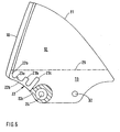
- the in the Fig. 1 shown embodiment of a fastening film 22 is provided with three finger-shaped portions 23 a, 23 b, 23 c, as enlarged in the Fig. 5 is shown.
- the fastening film 22 has at a front end 28 a front, guide web side portion 22 a, to which the lower end of the guide web 10 is attached.
- a rear portion 22b of the fastening film 22 connects.
- the rear portion 22 b is used for attachment to the rear side window eleventh
- a through opening 24 is formed in the rear side window 11, which serves via a screw connection 25 with an actuating device 26 not shown for moving the rear side window 11 from the extended position 14 in a retracted position not shown and back.
- the Fig. 2 shows a representation of the rear side window 11.
- a front edge 27 of the side window 11 of the guide bar 10 is attached.
- a front end 28 of the fastening film 22 is connected to the lower end 21 of the guide web 10.
- a dashed line 29 marks the transition from the visible area 12 of the rear side window 11 in the non-visible area 13 of the rear side window eleventh
- the fastening film 22 is fixed in the non-visible region 13 of the rear side window 11.
- the fastening film 22 has an end portion 22c which adjoins the rear portion 22b.
- the end portion 22 c is provided with a circular recess 31.
- the circular recess 31 surrounds the passage opening 24 of the rear side window 11.
- a further passage opening 32 is provided in the non-visible area 13 of the rear side window 11, are arranged on the parts of the actuator 26.
- the Fig. 3 shows the in the Fig. 2 shown fastening film 22.
- the fastening film 22 has a rear portion 22 b, which has an upper edge 34 which extends approximately horizontally or parallel to the dashed line 29.
- Fig. 4 a sectional view is shown, wherein the section along the line II in the Fig. 2 runs. From the sectional view, the connection of the rear side window 11 via an adhesive 35 with the guide web 10 is shown.
- the attachment foil 22 is glued on an outer surface 36 of the rear side window 11 facing towards the surroundings. Between the outer surface 36 of the rear side window 11 and an outer surface 37 of the fastening film 22, the adhesive 35 is applied, for example in the form of a bead and connected to an inner surface 38 of the guide web 10.
- a seal 39 is fixed with a closed cavity 40.
- the seal 39 comes in the extended position 14 of the rear side window 11 and in the extended position 8 of the front side window 7 in abutment against the rear side edge 9 of the front side window 7th
- the Fig. 5 shows a larger view of a rear side window 11 similar to that in the Fig. 2 shown side window 11.
- a second embodiment of a fastening film 22 is shown, which differs in that three finger-shaped portions 23a, 23b and 23c are provided. Unlike the one in the Fig. 2 shown fastening film 22, no end portion 22c is provided.
- the Fig. 6 corresponds to the illustration in the Fig. 5 with the difference that in addition to the finger-shaped portions 23a, 23b and 23c, an annular portion 21 is provided on the fastening film 22.
- the Fig. 7 shows a sectional view taken along the line II-II in the Fig. 2 ,
- the rear side window 11 is in the extended position 14.
- sealing lips 42, 43 are provided on both sides.
- the sealing lip 42 bears against an inner surface 44 facing a vehicle compartment and the sealing lip 43 abuts the outer surface 37 of the rear side window 11.
- the screw 25 has a radial extent D 25 with respect to an axis of symmetry 45.
- An inner diameter d 31 of the fastening film 22 is greater than the approximately circular surface of the screw 25 with the radial extent D 25th
- the Fig. 8 shows a state in which the rear side window 11 has been destroyed. Glass residues of the rear side window 11 stick to the fastening film 22.
- the guide web 10 is arranged on the body portion 16.
- the glass residues present on the fastening film 22 form a thickening section 46 with an outer diameter or a thickness t.
- the size and / or shape of the fastening film 22 is designed so that the forming thickening portion 46 has a thickness t which is greater than the gap width b in the cavity 15 of the body portion 16 leading through hole 18.
- the guide web 10 also remains after a destruction of the rear side window 11 connected at its mounting location with the body.
- the core idea of the invention is that after an accidental destruction of the rear side window 11 of the guide bar 10 remains fixed to the body 2 of the motor vehicle. This is inventively achieved by that the destruction of the rear side window 11 glass residues in the form of glass fragments on the fastening film 22 adhere. Glass residues and fastening foil 22 thereby form the thickening portion 46, which can not pass through the passage opening 18 of the body portion 16. The retention of the fastening film 22 is supported by the hooking of the glass residues with the sealing lips 42 and 43, respectively.
- the fastening film 22 may be arranged on the outer surface 36 and / or on the inner surface of the rear side window 11.
- the principle of the invention also works with a mounting film 22 without finger-shaped portions 23a, 23b and 23c, which fold over upon destruction of the rear side window 11 and thus increase the thickness t of the thickening portion 46.
- the effect of the invention is given when the fastening film 22 has no circular recess 31 in the region of the screw 25.
- the recess 31 is designed only as an additional fixation of the fastening film 22 on the body 2 of the motor vehicle.
Landscapes
- Engineering & Computer Science (AREA)
- Mechanical Engineering (AREA)
- Window Of Vehicle (AREA)
Claims (12)
- Véhicule automobile comportant des vitres latérales arrière, selon lequel,
chaque vitre latérale arrière (11) est délimitée par une entretoise de guidage (10) au niveau du bord arrière d'une vitre latérale avant lorsque la vitre latérale avant (7) et la vitre latérale arrière (11) se trouvent en position sortie,
la vitre latérale arrière (11) en position sortie, comporte une zone apparente (12) alors qu'une zone (13) non apparente de la vitre latérale arrière (11) se trouve dans une cavité (15) d'une partie de la carrosserie,
caractérisé en ce que
un film de fixation (22) est collé sur une surface (37, 44) de la vitre latérale arrière (11) située dans sa zone non apparente (13) et voisine de l'entretoise de guidage (10), ce film étant relié à l'entretoise de guidage (10). - Véhicule automobile selon la revendication 1,
caractérisé en ce que
à son extrémité avant (28) le film de fixation (22) comporte un segment avant (22a), du côté de l'entretoise de guidage, auquel est fixée l'extrémité inférieure (21) de l'entretoise de guidage (10), et
le segment avant (22a) se poursuit par un segment arrière (22b) du film de fixation (22) servant à sa fixation à la vitre latérale arrière (11). - Véhicule automobile selon la revendication 1 ou 2,
caractérisé en ce que
le film de fixation (22) est conçu pour qu'après la destruction de la vitre latérale arrière (11), des restes de vitre sont collés au film de fixation (22) qui constitue un segment de renforcement (46),
la dimension et/ou la forme du film de fixation (22) sont conçues pour que le segment de renforcement (46) qui se forme a une épaisseur (t) supérieure à la largeur (b) de l'intervalle d'un orifice de passage (18) débouchant dans la cavité (15) du segment de carrosserie (16). - Véhicule automobile selon la revendication 2 ou 3,
caractérisé en ce que
le segment arrière (22b) du film de fixation (22) constitue un segment de renforcement (46) après destruction de la vitre latérale arrière (11). - Véhicule automobile selon les revendications précédentes,
caractérisé par
un orifice de passage (24) réalisé dans la zone non apparente (13) de la vitre latérale arrière (11), et
une liaison vissée (25) est prévue dans l'orifice de passage (24), cette liaison étant reliée à un dispositif d'actionnement (26) pour déplacer la vitre latérale arrière (11) entre sa position déployée (14) et sa position rentrée. - Véhicule automobile selon les revendications précédentes,
caractérisé en ce que
le film de fixation (22) comporte un segment d'extrémité (22c) qui rejoint le segment arrière (22b) du film de fixation (22), et
le segment d'extrémité (22c) a une découpe circulaire (31). - Véhicule automobile selon la revendication 6,
caractérisé en ce que
le diamètre intérieur d3 de la découpe circulaire (31) est supérieur au diamètre extérieur D25 de la liaison vissée (25). - Véhicule automobile selon la revendication 6 ou 7,
caractérisé en ce que
la découpe circulaire (31) du film de fixation (22) est écartée de la liaison vissée (25). - Véhicule automobile selon la revendication 8,
caractérisé en ce que
la découpe circulaire (31) du film de fixation (22) est centrée sur la liaison vissée (25). - Véhicule automobile selon les revendications 2 à 9
caractérisé en ce que
le segment arrière (22b) du film de fixation (22) comporte des segments (23a, 23b, 23c) en forme de doigts. - Véhicule automobile selon les revendications 2 à 9,
caractérisé en ce que
le segment arrière (22b) du film de fixation (22) comporte une surface fermée. - Véhicule automobile selon les revendications précédentes,
caractérisé en ce que
le film de fixation (22) est en polyester ou en polyuréthane.
Applications Claiming Priority (2)
| Application Number | Priority Date | Filing Date | Title |
|---|---|---|---|
| DE200710009115 DE102007009115A1 (de) | 2007-02-24 | 2007-02-24 | Kraftfahrzeug mit hinteren Seitenscheiben |
| PCT/EP2008/001217 WO2008101641A1 (fr) | 2007-02-24 | 2008-02-16 | Véhicule automobile avec des vitres latérales arrière |
Publications (2)
| Publication Number | Publication Date |
|---|---|
| EP2054252A1 EP2054252A1 (fr) | 2009-05-06 |
| EP2054252B1 true EP2054252B1 (fr) | 2009-12-16 |
Family
ID=39344715
Family Applications (1)
| Application Number | Title | Priority Date | Filing Date |
|---|---|---|---|
| EP08715817A Active EP2054252B1 (fr) | 2007-02-24 | 2008-02-16 | Véhicule automobile avec des vitres latérales arrière |
Country Status (3)
| Country | Link |
|---|---|
| EP (1) | EP2054252B1 (fr) |
| DE (2) | DE102007009115A1 (fr) |
| WO (1) | WO2008101641A1 (fr) |
Families Citing this family (2)
| Publication number | Priority date | Publication date | Assignee | Title |
|---|---|---|---|---|
| DE102008049986A1 (de) * | 2008-10-01 | 2010-04-08 | Dr.Ing.H.C.F.Porsche Aktiengesellschaft | Kraftfahrzeug mit einer Fondseitenscheibe |
| FR2970207B1 (fr) * | 2011-01-06 | 2012-12-28 | Peugeot Citroen Automobiles Sa | Dispositif pour positionner la vitre d'une porte laterale de vehicule automobile par rapport a une commande d'ouverture exterieure de cette porte. |
Family Cites Families (8)
| Publication number | Priority date | Publication date | Assignee | Title |
|---|---|---|---|---|
| DE2809721C2 (de) * | 1978-03-07 | 1986-07-10 | Audi AG, 8070 Ingolstadt | Scheibenführung in einer Türe eines im Bereich der Verglasung mit glatter Außenfläche ausgebildeten Fahrzeugs |
| DE3632472A1 (de) * | 1986-09-24 | 1988-03-31 | Flachglas Ag | Kraftfahrzeugscheibe |
| DE3635924A1 (de) * | 1986-10-22 | 1988-05-11 | Daimler Benz Ag | Fahrzeugtuer oder karosserieabschnitt, insbesondere fuer einen personenkraftwagen |
| FR2783467B1 (fr) * | 1998-09-18 | 2001-05-11 | Aries Ind Structure | Dispositif de maintien de vitres de vehicules automobiles |
| DE10155168B4 (de) * | 2001-11-12 | 2005-02-10 | Webasto Systemkomponenten Gmbh & Co. Kg | Verfahren zum Herstellen eines lichtdurchlässigen Scheibenaufbaus für Fahrzeuge und lichtdurchlässiger Scheibenaufbau |
| DE10306758B4 (de) * | 2003-02-17 | 2007-04-12 | Webasto Ag | Fahrzeugfenster mit einer höhenverstellbaren Scheibe |
| DE202004020443U1 (de) * | 2004-02-18 | 2005-07-07 | Webasto Ag | Anordnung zum Verschließen einer Öffnung eines Fahrzeugs mit einer Scheibe und einem Splitterschutzelement |
| DE102004063513A1 (de) * | 2004-12-27 | 2006-07-06 | Brose Fahrzeugteile Gmbh & Co. Kommanditgesellschaft, Coburg | Türbaugruppe für ein Kraftfahrzeug |
-
2007
- 2007-02-24 DE DE200710009115 patent/DE102007009115A1/de not_active Withdrawn
-
2008
- 2008-02-16 EP EP08715817A patent/EP2054252B1/fr active Active
- 2008-02-16 WO PCT/EP2008/001217 patent/WO2008101641A1/fr not_active Ceased
- 2008-02-16 DE DE502008000253T patent/DE502008000253D1/de active Active
Also Published As
| Publication number | Publication date |
|---|---|
| DE102007009115A1 (de) | 2008-08-28 |
| WO2008101641A1 (fr) | 2008-08-28 |
| EP2054252A1 (fr) | 2009-05-06 |
| DE502008000253D1 (de) | 2010-01-28 |
Similar Documents
| Publication | Publication Date | Title |
|---|---|---|
| DE20321549U1 (de) | Dicht-, Trimm- oder Führungsleiste | |
| EP1781483B1 (fr) | Bourrelet d'etancheite pour fenetres laterales sans cadre de vehicules automobiles | |
| DE102010061103A1 (de) | Scheibeneinheit und Verfahren zu deren Herstellung | |
| DE102019128241A1 (de) | Türmodul mit rahmenloser glaskonfiguration mit einstellbaren glaslaufkanälen | |
| DE2809721B1 (de) | Scheibenfuehrung in einem Fahrzeug | |
| DE60320276T9 (de) | Dichtungs-, zier- oder führungsstreifen | |
| DE102014013772A1 (de) | Fahrzeugtür für ein Fahrzeug sowie Fahrzeug mit einer solchen Fahrzeugtür | |
| DE102014005721B3 (de) | Scheibenanordnung für ein Kraftfahrzeug | |
| DE102008005230A1 (de) | Klappe für Fahrzeuge | |
| DE4426744A1 (de) | Höhenverstellbares Seitenfenster für Kraftfahrzeuge | |
| DE102007007457B4 (de) | Innenverkleidung für eine Kraftfahrzeugtür | |
| DE102007044426B4 (de) | Vorrichtung zur Abdichtung eines Fensterschachts an einer Kraftfahrzeugtür | |
| EP2054252A1 (fr) | Véhicule automobile avec des vitres latérales arrière | |
| EP4200147B1 (fr) | Ensemble joint d'étanchéité pour une fenêtre de véhicule agencée sur un véhicule | |
| DE3904486C1 (en) | Deployable, transparent roof part for motor vehicles | |
| DE102017124228B4 (de) | Fahrzeugseitenstruktur und Kraftfahrzeug | |
| DE10157001C1 (de) | Dichtungssystem für eine Tür, insbesondere an einem Fahrzeug | |
| DE60033883T2 (de) | Abschlussvorrichtung für Öffnung in einer Fahrzeugkarosserie mit Wasserdurchfuhr | |
| EP1818202A1 (fr) | Segment de colonne B pour un véhicule cabriolet | |
| WO2012167879A2 (fr) | Composant de véhicule | |
| EP1329347B1 (fr) | Véhicule avec une fenètre latérale pivotante | |
| DE10325824B4 (de) | Fahrzeugdach mit einer Dichtungsanordnung sowie Dichtungsanordnung für eine Öffnung in einer Fahrzeugaußenhaut | |
| DE102024135246B3 (de) | Scheibeneinheit für ein Fenster an Kraftfahrzeugen | |
| DE102015210447B4 (de) | Dichtungsanordnung für ein Spiegeldreieck einer Kraftwagenseitentür | |
| WO2019011783A1 (fr) | Support pour élément de surface d'un dispositif d'occultation ou de protection solaire et dispositif d'occultation ou de protection solaire |
Legal Events
| Date | Code | Title | Description |
|---|---|---|---|
| PUAI | Public reference made under article 153(3) epc to a published international application that has entered the european phase |
Free format text: ORIGINAL CODE: 0009012 |
|
| 17P | Request for examination filed |
Effective date: 20090319 |
|
| AK | Designated contracting states |
Kind code of ref document: A1 Designated state(s): DE FR GB IT |
|
| AX | Request for extension of the european patent |
Extension state: AL BA MK RS |
|
| GRAP | Despatch of communication of intention to grant a patent |
Free format text: ORIGINAL CODE: EPIDOSNIGR1 |
|
| GRAS | Grant fee paid |
Free format text: ORIGINAL CODE: EPIDOSNIGR3 |
|
| GRAA | (expected) grant |
Free format text: ORIGINAL CODE: 0009210 |
|
| AK | Designated contracting states |
Kind code of ref document: B1 Designated state(s): DE FR GB IT |
|
| REG | Reference to a national code |
Ref country code: GB Ref legal event code: FG4D Free format text: NOT ENGLISH |
|
| REF | Corresponds to: |
Ref document number: 502008000253 Country of ref document: DE Date of ref document: 20100128 Kind code of ref document: P |
|
| PLBE | No opposition filed within time limit |
Free format text: ORIGINAL CODE: 0009261 |
|
| STAA | Information on the status of an ep patent application or granted ep patent |
Free format text: STATUS: NO OPPOSITION FILED WITHIN TIME LIMIT |
|
| 26N | No opposition filed |
Effective date: 20100917 |
|
| REG | Reference to a national code |
Ref country code: FR Ref legal event code: PLFP Year of fee payment: 9 |
|
| REG | Reference to a national code |
Ref country code: FR Ref legal event code: PLFP Year of fee payment: 10 |
|
| REG | Reference to a national code |
Ref country code: FR Ref legal event code: PLFP Year of fee payment: 11 |
|
| P01 | Opt-out of the competence of the unified patent court (upc) registered |
Effective date: 20230502 |
|
| PGFP | Annual fee paid to national office [announced via postgrant information from national office to epo] |
Ref country code: GB Payment date: 20260219 Year of fee payment: 19 |
|
| PGFP | Annual fee paid to national office [announced via postgrant information from national office to epo] |
Ref country code: DE Payment date: 20260210 Year of fee payment: 19 |
|
| PGFP | Annual fee paid to national office [announced via postgrant information from national office to epo] |
Ref country code: IT Payment date: 20260227 Year of fee payment: 19 |
|
| PGFP | Annual fee paid to national office [announced via postgrant information from national office to epo] |
Ref country code: FR Payment date: 20260223 Year of fee payment: 19 |