EP2054888B1 - Système optique, appareil de lecture optique, et appareil à disque optique conçu pour extraire des faisceaux de signaux - Google Patents
Système optique, appareil de lecture optique, et appareil à disque optique conçu pour extraire des faisceaux de signaux Download PDFInfo
- Publication number
- EP2054888B1 EP2054888B1 EP07792690A EP07792690A EP2054888B1 EP 2054888 B1 EP2054888 B1 EP 2054888B1 EP 07792690 A EP07792690 A EP 07792690A EP 07792690 A EP07792690 A EP 07792690A EP 2054888 B1 EP2054888 B1 EP 2054888B1
- Authority
- EP
- European Patent Office
- Prior art keywords
- beams
- rays
- optical
- bundle
- reflected
- Prior art date
- Legal status (The legal status is an assumption and is not a legal conclusion. Google has not performed a legal analysis and makes no representation as to the accuracy of the status listed.)
- Not-in-force
Links
- 230000003287 optical effect Effects 0.000 title claims abstract description 405
- 230000010287 polarization Effects 0.000 claims description 211
- 239000012780 transparent material Substances 0.000 claims description 8
- 230000001678 irradiating effect Effects 0.000 claims description 7
- 239000010410 layer Substances 0.000 description 94
- 238000000034 method Methods 0.000 description 35
- 230000008569 process Effects 0.000 description 30
- 238000010586 diagram Methods 0.000 description 28
- 230000008878 coupling Effects 0.000 description 14
- 238000010168 coupling process Methods 0.000 description 14
- 238000005859 coupling reaction Methods 0.000 description 14
- 238000006243 chemical reaction Methods 0.000 description 12
- 239000004065 semiconductor Substances 0.000 description 10
- 230000000694 effects Effects 0.000 description 4
- 239000000284 extract Substances 0.000 description 4
- 239000000758 substrate Substances 0.000 description 4
- 238000005516 engineering process Methods 0.000 description 3
- 239000004038 photonic crystal Substances 0.000 description 3
- 230000009467 reduction Effects 0.000 description 3
- 238000002834 transmittance Methods 0.000 description 3
- 239000004988 Nematic liquid crystal Substances 0.000 description 2
- 238000012937 correction Methods 0.000 description 2
- 238000001514 detection method Methods 0.000 description 2
- 238000005530 etching Methods 0.000 description 2
- 238000001914 filtration Methods 0.000 description 2
- 239000011229 interlayer Substances 0.000 description 2
- 238000004519 manufacturing process Methods 0.000 description 2
- 229910052751 metal Inorganic materials 0.000 description 2
- 239000002184 metal Substances 0.000 description 2
- 239000007769 metal material Substances 0.000 description 2
- 230000000979 retarding effect Effects 0.000 description 2
- 238000003848 UV Light-Curing Methods 0.000 description 1
- 230000002411 adverse Effects 0.000 description 1
- 230000004075 alteration Effects 0.000 description 1
- 229910052782 aluminium Inorganic materials 0.000 description 1
- XAGFODPZIPBFFR-UHFFFAOYSA-N aluminium Chemical compound [Al] XAGFODPZIPBFFR-UHFFFAOYSA-N 0.000 description 1
- 230000007175 bidirectional communication Effects 0.000 description 1
- 238000004590 computer program Methods 0.000 description 1
- 238000013144 data compression Methods 0.000 description 1
- 238000013500 data storage Methods 0.000 description 1
- 230000003247 decreasing effect Effects 0.000 description 1
- 239000003989 dielectric material Substances 0.000 description 1
- 239000002355 dual-layer Substances 0.000 description 1
- PCHJSUWPFVWCPO-UHFFFAOYSA-N gold Chemical compound [Au] PCHJSUWPFVWCPO-UHFFFAOYSA-N 0.000 description 1
- 239000010931 gold Substances 0.000 description 1
- 229910052737 gold Inorganic materials 0.000 description 1
- 230000006872 improvement Effects 0.000 description 1
- 230000001788 irregular Effects 0.000 description 1
- 239000000463 material Substances 0.000 description 1
- 238000012986 modification Methods 0.000 description 1
- 230000004048 modification Effects 0.000 description 1
- 238000011160 research Methods 0.000 description 1
- 239000011347 resin Substances 0.000 description 1
- 229920005989 resin Polymers 0.000 description 1
- 230000000699 topical effect Effects 0.000 description 1
Images











Classifications
-
- G—PHYSICS
- G11—INFORMATION STORAGE
- G11B—INFORMATION STORAGE BASED ON RELATIVE MOVEMENT BETWEEN RECORD CARRIER AND TRANSDUCER
- G11B7/00—Recording or reproducing by optical means, e.g. recording using a thermal beam of optical radiation by modifying optical properties or the physical structure, reproducing using an optical beam at lower power by sensing optical properties; Record carriers therefor
- G11B7/12—Heads, e.g. forming of the optical beam spot or modulation of the optical beam
- G11B7/135—Means for guiding the beam from the source to the record carrier or from the record carrier to the detector
- G11B7/1365—Separate or integrated refractive elements, e.g. wave plates
-
- G—PHYSICS
- G11—INFORMATION STORAGE
- G11B—INFORMATION STORAGE BASED ON RELATIVE MOVEMENT BETWEEN RECORD CARRIER AND TRANSDUCER
- G11B7/00—Recording or reproducing by optical means, e.g. recording using a thermal beam of optical radiation by modifying optical properties or the physical structure, reproducing using an optical beam at lower power by sensing optical properties; Record carriers therefor
- G11B7/004—Recording, reproducing or erasing methods; Read, write or erase circuits therefor
- G11B7/005—Reproducing
-
- G—PHYSICS
- G11—INFORMATION STORAGE
- G11B—INFORMATION STORAGE BASED ON RELATIVE MOVEMENT BETWEEN RECORD CARRIER AND TRANSDUCER
- G11B7/00—Recording or reproducing by optical means, e.g. recording using a thermal beam of optical radiation by modifying optical properties or the physical structure, reproducing using an optical beam at lower power by sensing optical properties; Record carriers therefor
- G11B7/08—Disposition or mounting of heads or light sources relatively to record carriers
- G11B7/09—Disposition or mounting of heads or light sources relatively to record carriers with provision for moving the light beam or focus plane for the purpose of maintaining alignment of the light beam relative to the record carrier during transducing operation, e.g. to compensate for surface irregularities of the latter or for track following
- G11B7/0943—Methods and circuits for performing mathematical operations on individual detector segment outputs
-
- G—PHYSICS
- G11—INFORMATION STORAGE
- G11B—INFORMATION STORAGE BASED ON RELATIVE MOVEMENT BETWEEN RECORD CARRIER AND TRANSDUCER
- G11B7/00—Recording or reproducing by optical means, e.g. recording using a thermal beam of optical radiation by modifying optical properties or the physical structure, reproducing using an optical beam at lower power by sensing optical properties; Record carriers therefor
- G11B7/12—Heads, e.g. forming of the optical beam spot or modulation of the optical beam
- G11B7/13—Optical detectors therefor
- G11B7/131—Arrangement of detectors in a multiple array
-
- G—PHYSICS
- G11—INFORMATION STORAGE
- G11B—INFORMATION STORAGE BASED ON RELATIVE MOVEMENT BETWEEN RECORD CARRIER AND TRANSDUCER
- G11B7/00—Recording or reproducing by optical means, e.g. recording using a thermal beam of optical radiation by modifying optical properties or the physical structure, reproducing using an optical beam at lower power by sensing optical properties; Record carriers therefor
- G11B7/12—Heads, e.g. forming of the optical beam spot or modulation of the optical beam
- G11B7/135—Means for guiding the beam from the source to the record carrier or from the record carrier to the detector
- G11B7/1353—Diffractive elements, e.g. holograms or gratings
-
- G—PHYSICS
- G11—INFORMATION STORAGE
- G11B—INFORMATION STORAGE BASED ON RELATIVE MOVEMENT BETWEEN RECORD CARRIER AND TRANSDUCER
- G11B7/00—Recording or reproducing by optical means, e.g. recording using a thermal beam of optical radiation by modifying optical properties or the physical structure, reproducing using an optical beam at lower power by sensing optical properties; Record carriers therefor
- G11B7/12—Heads, e.g. forming of the optical beam spot or modulation of the optical beam
- G11B7/135—Means for guiding the beam from the source to the record carrier or from the record carrier to the detector
- G11B7/1356—Double or multiple prisms, i.e. having two or more prisms in cooperation
-
- G—PHYSICS
- G11—INFORMATION STORAGE
- G11B—INFORMATION STORAGE BASED ON RELATIVE MOVEMENT BETWEEN RECORD CARRIER AND TRANSDUCER
- G11B7/00—Recording or reproducing by optical means, e.g. recording using a thermal beam of optical radiation by modifying optical properties or the physical structure, reproducing using an optical beam at lower power by sensing optical properties; Record carriers therefor
- G11B7/12—Heads, e.g. forming of the optical beam spot or modulation of the optical beam
- G11B7/135—Means for guiding the beam from the source to the record carrier or from the record carrier to the detector
- G11B7/1365—Separate or integrated refractive elements, e.g. wave plates
- G11B7/1367—Stepped phase plates
-
- G—PHYSICS
- G11—INFORMATION STORAGE
- G11B—INFORMATION STORAGE BASED ON RELATIVE MOVEMENT BETWEEN RECORD CARRIER AND TRANSDUCER
- G11B7/00—Recording or reproducing by optical means, e.g. recording using a thermal beam of optical radiation by modifying optical properties or the physical structure, reproducing using an optical beam at lower power by sensing optical properties; Record carriers therefor
- G11B7/12—Heads, e.g. forming of the optical beam spot or modulation of the optical beam
- G11B7/135—Means for guiding the beam from the source to the record carrier or from the record carrier to the detector
- G11B7/1365—Separate or integrated refractive elements, e.g. wave plates
- G11B7/1369—Active plates, e.g. liquid crystal panels or electrostrictive elements
-
- G—PHYSICS
- G11—INFORMATION STORAGE
- G11B—INFORMATION STORAGE BASED ON RELATIVE MOVEMENT BETWEEN RECORD CARRIER AND TRANSDUCER
- G11B7/00—Recording or reproducing by optical means, e.g. recording using a thermal beam of optical radiation by modifying optical properties or the physical structure, reproducing using an optical beam at lower power by sensing optical properties; Record carriers therefor
- G11B7/12—Heads, e.g. forming of the optical beam spot or modulation of the optical beam
- G11B7/135—Means for guiding the beam from the source to the record carrier or from the record carrier to the detector
- G11B7/1381—Non-lens elements for altering the properties of the beam, e.g. knife edges, slits, filters or stops
-
- G—PHYSICS
- G11—INFORMATION STORAGE
- G11B—INFORMATION STORAGE BASED ON RELATIVE MOVEMENT BETWEEN RECORD CARRIER AND TRANSDUCER
- G11B7/00—Recording or reproducing by optical means, e.g. recording using a thermal beam of optical radiation by modifying optical properties or the physical structure, reproducing using an optical beam at lower power by sensing optical properties; Record carriers therefor
- G11B2007/0003—Recording, reproducing or erasing systems characterised by the structure or type of the carrier
- G11B2007/0009—Recording, reproducing or erasing systems characterised by the structure or type of the carrier for carriers having data stored in three dimensions, e.g. volume storage
- G11B2007/0013—Recording, reproducing or erasing systems characterised by the structure or type of the carrier for carriers having data stored in three dimensions, e.g. volume storage for carriers having multiple discrete layers
-
- G—PHYSICS
- G11—INFORMATION STORAGE
- G11B—INFORMATION STORAGE BASED ON RELATIVE MOVEMENT BETWEEN RECORD CARRIER AND TRANSDUCER
- G11B7/00—Recording or reproducing by optical means, e.g. recording using a thermal beam of optical radiation by modifying optical properties or the physical structure, reproducing using an optical beam at lower power by sensing optical properties; Record carriers therefor
- G11B7/12—Heads, e.g. forming of the optical beam spot or modulation of the optical beam
- G11B7/14—Heads, e.g. forming of the optical beam spot or modulation of the optical beam specially adapted to record on, or to reproduce from, more than one track simultaneously
Definitions
- the present invention relates to an optical system, an optical pickup apparatus, and an optical disc apparatus, and more particularly to an optical system for extracting signal beams from a bundle of rays including signal beams and stray beams, an optical pickup apparatus including the optical system, and an optical disc apparatus including the optical pickup apparatus,
- optical discs e.g., CDs (Compact Disc) and DVDs (Digital Versatile Disc) serving to record computer programs, audio information, video information (hereinafter also referred to as "contents") are drawing greater attention due to the advances in digital technology and the improvement in data compression technology. Accordingly, as the optical discsbecome less expensive, optical disc apparatuses for reproducing the information recorded in the optical discs have grown to become widely used.
- multilayer disc optical discs having plural recording layers (hereinafter referred to as "multilayer disc:”) and optical disc apparatuses that access the multilayered discs.
- the signals from a target recording layer be adversely affected by spherical aberration if the spaces between the recording layers are too large. Accordingly, there is a trend of reducing the space between the recording layers.
- reducing the space between the recording layers causes cross-talk between the recording layers (so-called “interlayer cross-talk").
- the bundle of rays returning (reflected) from the multilayer disc contains not only desired beams reflected from a target recording layer (hereinafter referred to as "signal beams”) but also a significant amount of undesired beams reflected from recording layers besides the target recording layer (hereinafter referred to as "stray beams"). This leads to the decrease in S/N ratio of reproduction signals.
- Japanese Registered Patent No. 2624255 requires the diameter of a pinhole to be further reduced in order to further reduce stray beams incident on a detector.
- the reduction of incident stray beams leads to undesired reduction of signal beams incident on the detector.
- the signal tight passes through two quarter wave-plate segments of the same sign (++ - or --), thus becoming linearly polarized in the horizontal direction. Because the stray light is out of focus, it passes through two quarter wave-plates of the opposite sign (+- or -+), thus becoming linearly polarized in the vertical direction.
- a polarized beam splitter separates the stray light from the signal light.
- WO 2006/093326 A1 representing prior art according to Article 54(3) EPC, describes a multilayer reproduction system using different diffraction orders of the reflected beam with a stray light filter arrangement where plural non-segmented waveplates are combined with shielding plates arranged in the optical path in order to achieve the desired filtering effect.
- WO 2006/043572 A1 describes multi-beam tracking using different diffraction orders generated by a diffraction grating.
- the present invention may provide an optical system, an optical pickup apparatus, and an optical disc apparatus that substantially obviate one or more of the problems caused by the limitations and disadvantages of the related art.
- Another embodiment of the present invention provides an optical system according to claim 4.
- Another embodiment of the present invention provides an optical pickup apparatus according to claim 10.
- Another embodiment of the present invention provides an optical disc apparatus according to claim 12.
- Fig.1 is a schematic diagram showing a configuration of an optical disc apparatus 20 according to an embodiment of the present invention.
- the optical disc apparatus 20 shown in Fig.1 includes, for example, a spindle motor 22 for rotating an optical disc 15, an optical pickup apparatus 23, a seek motor 21 for driving the optical pickup apparatus 23 in a radial direction of the optical disc 15, a laser control circuit 24, an encoder 25, a drive control circuit 26, a reproduction signal process circuit 28, a buffer RAM 34, a buffer manager 37, an interface 38, a flash memory 39, a CPU 40, and a RAM 41.
- the spindle motor 22 is for rotating an optical disc 15.
- the arrows illustrated in Fig.1 indicate an exemplary flow of signals and information and do not indicate all connections among the blocks (components) illustrated in Fig.1 .
- the optical disc apparatus 20 according to an embodiment of the present invention is applicable to a multilayer disc.
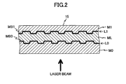
- the optical disc 15 includes, for example, a first substrate M0, a first recording layer L0, an intermediate layer ML, a second recording layer L1, and a second substrate M1 that are layered in this order from an incident direction of a bundle of rays (arrow direction of laser beam in Figs. 2 ) to the optical disc 15.
- a translucent film MB0 that is formed of, for example, a metal material (e.g. , gold) or a dielectric material is provided between the first recording layer L0 and the intermediate layer ML.
- a reflection film MB1 that is formed of, for example, a metal material (e.g., aluminum) is provided between the second recording layer L1 and the second substrate M1.
- the intermediate layer ML includes a UV curing resin material having high transmittance with respect to the irradiated bundle of rays and a refractive index that is similar to that of the substrates. That is, the optical disc 15 is a single sided dual layer disc. Each recording layer has one or more tracks formed with spiral or concentric guiding grooves.
- the optical disc 15 has the first recording layer L0 situated closer to the optical disc apparatus 20 than the second recording layer L1. Accordingly, a portion of the bundle of rays incident on the optical disc 15 is reflected at the translucent film MB0, and the remaining portion of the bundle of rays is transmitted through the translucent film MB0. Then, the bundle of rays transmitted through the translucent film MB0 is reflected by the reflection film MB1.
- the optical disc 15 is a DVD type information recording medium.
- the optical pickup apparatus 23 is for irradiating a laser beam onto one of the two recording layers of the optical disc 15 to which access is sought (hereinafter referred to as "target recording layer") and for receiving rays of light reflected from the optical disc 15.
- the optical pickup apparatus 23 includes, for example, a light source unit 51, a coupling lens 52, a grating 200, a 1/4 wave plate 55, an objective lens 60, an optical system 70, a condenser lens 58, a photo detector PD serving as a light receiving unit and a drive system including a focusing actuator AC and a tracking actuator (not shown) for driving the objective lens 60.
- the optical system 70 includes a polarization beam splitter 54 serving as a polarizer, a lens 61 serving as a condensing optical element, two polarization converting optical elements (192, 193), and an analyzer 64.
- the light source unit 51 includes, for example, a semiconductor laser serving as a light source for irradiating a laser beam having a wavelength complying with the optical disc 15 (in this example, approximately 660 nm).
- the direction of the laser beam of the maximum strength irradiated from the light source unit 51 is in the +X direction.
- the light source unit 51 irradiates, for example, a bundle of polarized rays that is parallel to the incident plane of the polarization beam splitter 54 (P polarized light).
- the coupling lens 52 being positioned at the +X side of the light source unit 51, makes the bundle of rays irradiated from the light source unit 51 into substantially parallel rays.
- the grating 200 is positioned at the +X side of the coupling lens 52.
- the grating 200 divides the substantially parallel rays from the coupling lens 52 into three bundles of rays which are a 0 th order beam (hereinafter also referred to as "0 th order light”), a positive first order diffraction beam (hereinafter also referred to as "+1 st order beam” or “+1 st order light”), and a negative first order diffraction beam (hereinafter also referred to as "-1 st order beam” or "-1 st order light”). That is, the grating 200 changes the incident bundle of rays into three beams.
- the grating 200 divides the incident rays so that 80% of the bundle of incident rays becomes the 0 th order beam, 10% of the bundle of incident rays becomes the +1 st order beam, and 10% of the bundle of incident rays becomes the -1 st order beam.
- the +1 st order beam and the -1 st order beam may hereinafter be collectively referred to as " ⁇ 1 st order beam" for the sake of convenience.
- the polarization beam splitter 54 is positioned at the +X side of the grating 200.
- the reflectance of the polarization beamsplitter54 varies depending on the polarization of the incident bundle of rays.
- the polarization beam splitter 54 is set to have decreasing reflectance with respect to the P polarized beam and an increasing reflectance with respect to the S polarized beam. That is, the polarization beam splitter 54 splits the S polarized beam included in the incident bundle of rays. Therefore, a large portion of the bundle of rays irradiated from the light source unit 51 can transmit through the polarization beam splitter 54.
- the 1/4 wave plate 55 is positioned at the +X side of the polarization beam splitter 54.
- the 1/4 wave plate 55 provides a phase difference of a 1/4 wavelength with respect to the bundle of rays incident on the 1/4 wave plate 55.
- the objective lens 60 being positioned at the +X side of the 1/4 wave plate 55, condenses the bundle of rays transmitted through the 1/4 wave plate onto the target recording layer.
- the optical pickup apparatus 23 is set to condense the 0 th order beam on the groove of the target recording layer and condense each of the +1 st and -1 st order beams to a corresponding land situated adjacent to the groove onto which the 0 th order beam is condensed.
- the focusing actuator AC is for precisely driving (moving) the objective lens 60 in the focus direction, that is, the direction of the optical axis of the objective lens 60.
- first lens position the optimum position of the objective lens 60 with respect to the focus direction
- second lens position the optimum position of the objective lens 60 with respect to the focus direction
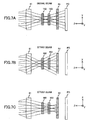
- the distance between the objective lens 60 and the optical disk 15 is shorter in a case where the objective lens 60 is in the second lens position compared to a case where the objective lens 60 is in the first lens position (See Figs. 4A and 4B ).
- the tracking actuator (not shown) is for precisely driving (moving) the objective lens 60 in the tracking direction.
- the position of the objective lens 60 is define as the first lens position. Accordingly, the objective lens 60 condenses the bundle of rays irradiated from the light source unit 51 onto the first recording layer L0. Then, a portion of the bundle of rays is reflected from the translucent film MB0 and is incident on the objective lens 60. Such portion of the bundle of rays reflected from the translucent film MB0 includes a signal beam(s) (hereinafter also referred to as "signal light”) . Meanwhile, the remaining portion of the bundle of rays is transmitted through the translucent film MB0, is reflected from the reflection film MB1, and is incident on the objective lens 60. The remaining portion of the bundle of rays reflected from the reflection film MB1 includes stray beam(s) (hereinafter also referred to as "stray light").
- the bundle of rays reflected from the optical disc 15 includes a bundle of rays reflected from the translucent film MB0 (hereinafter referred to as "first reflected beam”) and another bundle of rays reflected from the metal reflection film MB1 (hereinafter referred to as "second reflected beam”).
- first reflected beam is a signal beam
- second reflected beam is a stray beam.
- the second reflected beam is a signal beam and the first reflected beam is a stray beam.
- the first reflected beam comprises a reflected beam of the 0 th order beam and reflected beams of the ⁇ 1 st order beams.
- the second reflected beam comprises a reflected beam of the 0 th order beam and reflected beams of the ⁇ 1 st order beams.
- a signal beam may be plural signal beams that include a signal beam of the 0 th order beam and signal beams of the ⁇ 1 st order beams
- a stray beam may be plural stray beams that include a stray beam of the 0 th order beam and stray beams of the ⁇ 1 st order beams.
- the lens 61 being situated at the -Z side of the polarization beam splitter 54, condenses the reflected bundles of rays split and oriented in the -Z direction by the polarization beam splitter 54.
- the reflected beam of the +1 st order beam is condensed to the +X side of the area to which the 0 th order beam is condensed and the reflected beam of the -1 st order beam is condensed to the -X side of the area to which the 0 th order beam is condensed.
- the reflected beam of the +1 st order beam is condensed to the +X side of the area to which the 0 th order beam is condensed and the reflected beam of the -1 st order beam is condensed to the -X side of the area to which the 0 th order beam is condensed.
- An imaginary plane which includes the area where the reflected beam of the 0 th order beam and the reflected beams of the ⁇ 1 st order beams reflected from the same recording layer are condensed from the same recording layer, is referred to as a "condensing plane".
- the condensing plane of the first reflection beam and the condensing plane of the second reflection beam do not match. That is, the condensing plane of the first reflection beam and the condensing plane of the second reflection beam are separated from each other with respect to the direction of the optical axis of the lens 61.
- the polarization converting optical element 192 is located on the -Z side of the lens 61 and interposed between the condensing plane of plural signal beams from the target recording layer and the condensing plane of plural stray beams from a recording layer (in this example, second recording layer L1 when the target recording layer is L0) adjacently positioned on the +X side of the target recording layer.
- the polarization converting optical element 192 may be divided into, for example, six areas (192a, 192b, 192c, 192d, 192e, 192f) by five dividing lines (192i, 192j, 192k, 1921, 192m) extending in the Y axis direction.
- areas 192a, 192c, and 192e each add retardation (optical phase difference) of -1/4 wavelength to an incident bundle of rays
- areas 192b, 192d, and 192f each add retardation of +1/4 wavelength to an incident bundle of rays.
- the optical pickup apparatus 23 is set so that the +1 st order beam is incident on the areas 192a and 192b, the 0 th order beam is incident on the areas 192c and 192d, and the -1 st order beam is incident on the areas 192e and 192f.
- the polarization converting optical element 193 is located on the -Z side of the polarization converting optical element 192 and interposed between the condensing plane of plural signal beams from the target recording layer and the condensing plane of plural stray beams from a recording layer (in this example, first recording layer L0 when the target recording layer is L1) adjacently positioned on the -X side of the target recording layer.
- the polarization converting optical element 193 may be divided into, for example, six areas (193a, 193b, 193c, 193d, 193e, 193f) by five dividing lines (193i, 193j, 193k, 1931, 193m) extending in the Y axis direction.
- areas 193a, 193c, and 193e each add retardation (optical phase difference) of +1/4 wavelength to the incident bundle of rays
- areas 193b, 193d, and 193f each add retardation of -1/4 wavelength to the incident bundle of rays.
- a twisted nematic liquid crystal, a sub-wavelength wire-grid, or a photonic crystal may be used as the polarization converting optical elements 192, 193.
- the analyzer 64 being positioned at the -Z side of the polarization converting optical element 163, only allows P polarized beams included in the bundle of rays from the polarization converting optical element 193 to transmit therethrough.
- the condenser lens 58 which is located on the -Z side of the analyzer 64, condenses the reflected bundle of rays transmitted through the analyzer 64 onto the light receiving plane of the photo-detector PD.
- the photo-detector PD has plural photo-detecting elements (or photo-detection areas) for generating signals (photo-electric conversion signals) that are optimum for detecting, for example, RF signals, wobble signals, and servo signals in the reproduction signal process circuit 28.
- the bundle of rays of a linearly polarized beam (in this example, P polarized beam) from the light source unit 51 is made into a bundle of substantially parallel rays by the coupling lens 52. Then, the bundle of parallel rays is divided into three beams (0 th order beam and ⁇ 1 st order beams) by the grating 200. Then, the three beams become incident on the polarization beam splitter 54. A large portion of each beam is transmitted through the polarization beam splitter 54 maintaining its parallel state, is circularly polarized by the 1/4 wave plate 55, and is condensed onto the optical disc 15 by the objective lens 60, to thereby form three fine beam spots on the target recording layer L0.
- P polarized beam linearly polarized beam
- bundles of rays are reflected from the optical disc 15 in which the reflected bundles of rays include plural signal beams from the recording layer L0 and plural stray beams from the recording layer L1.
- the bundles of rays become circularly polarized in an opposite rotating direction (with respect to that of the circularly polarized rays irradiated onto the optical disc 15) and are again made into substantially parallel rays by the objective lens 60.
- the reflected bundles of parallel rays are made into linearly polarized beams (in this example, S polarized beam) that perpendicularly intersect (with respect to that of the circularly polarized rays irradiated onto the optical disc 15) at the 1/4 wave plate 55.
- the reflected bundles of rays become incident on the polarization beam splitter 54.
- the bundles of rays are reflected in the -Z direction by the polarization beam splitter 54 and condensed at the lens 61.
- the reflected bundles of rays transmitted through the lens 61 are incident on the polarization converting optical element 192.
- the +1 st order beam of the signal beam and the +1 st order beam of the stray beam are incident on the areas 192a and 192b
- the 0 th order beam of the signal beam and the 0 th order beam of the stray beam are incident on the areas 192c and 192d
- the -1 st order beam of the signal beam and the -1 st order beam of the stray beam are incident on the areas 192e and 192f.
- each of the +1 st order beams incident on the area 192a is retarded by -1/4 wavelength and each of the +1 st order beams incident on the area 192b is retarded by +1/4 wavelength.
- each of the 0 th order beams incident on the area 192c is retarded by -1/4 wavelength and each of the 0 th order beams incident on the area 192d is retarded by +1/4 wavelength.
- each of the -1 st order beams incident on the area 192e is retarded by -1/4 wavelength and each of the -1 st order beams incident on the area 192f is retarded by +1/4 wavelength.
- both the signal beam and the stray beam are S polarized beams between the lens 61 and the polarization converting optical element 192.
- Each bundle of rays from the polarization converting optical element 192 is incident on the polarization converting optical element 193.
- the signal beams of the +1 st order beams transmitted through the area 192a are incident on the area 193b and retarded by -1/4 wavelength.
- the signal beams of the +1 st order beams transmitted through the area 192b are incident on the area 193a and retarded by +1/4 wavelength.
- the signal beams of the 0 th order beams transmitted through the area 192c (0 th order beams retarded by -1/4 wavelength) are incident on the area 193d and retarded by -1/4 wavelength.
- the signal beams of the 0 th order beams transmitted through the area 192d (0 th order beams retarded by +1/4 wavelength) are incident on the area 193c and retarded by +1/4 wavelength.
- the signal beams of the -1 st order beams transmitted through the area 192e (-1 st order beams retarded by -1/4 wavelength) are incident on the area 193f and retarded by -1/4 wavelength.
- the -1 st order beams transmitted through the area 192f (-1 st order beams retarded by +1/4 wavelength) are incident on the area 193e and retarded by +1/4 wavelength. Accordingly, the plural signal beams all become P polarized beams.
- the stray beams of the +1 st order beams transmitted via the area 192a are incident on the area 193a and retarded by +1/4 wavelength.
- the stray beams of the +1 st order beams transmitted via the area 192b are incident on the area 193b and are retarded by -1/4 wavelength.
- the stray beams of the 0 th order beams transmitted via the area 192c (0 th order beams retarded by -1/4 wavelength) are incident on the area 193c and retarded by +1/4 wavelength.
- the stray beams of the 0 th order beams transmitted through the area 192d (0 th order beams retarded by +1/4 wavelength) are incident on the area 193d and retarded by -1/4 wavelength.
- the stray beams of the -1 st order beams transmitted through the area 192e (-1 st border beams retarded by -1/4 wavelength) are incident on the area 193e and retarded by +1/4 wavelength.
- the stray beams of the -1 st order beams transmitted through the area 192f (-1 st order beams retarded by +1/4 wavelength) are incident on the area 193f and retarded by -1/4 wavelength. Accordingly, the plural stray beams all remain S polarized beams.
- the bundle of rays from the polarization converting optical element 193 is incident on the analyzer 64. Since the analyzer 64 only allows P polarized beams to transmit therethrough, only the plural signal beams are incident on the condenser lens 58 and received by the photo-detector PD. Each light receiving element (light receiving area) of the photo-detector PD performs photo-electric conversion and outputs photo-electric conversion signals to the reproduction signal process circuit 28. Since only plural signal beams are received at the photo-detector PD, photo-electric conversion signals having high S/N ratio can be output.
- the bundle of rays of a linearly polarized beam (in this example, P polarized beam) from the light source unit 51 is made into a bundle of substantially parallel rays by the coupling lens 52. Then, the bundle of parallel rays is divided into three beams (0 th order beam and ⁇ 1 st order beams) by the grating 200. Then, the three beams become incident on the polarization beam splitter 54. A large portion of each beam, which is transmitted through the polarization beam splitter 54 maintaining its parallel state, is circularly polarized by the 1/4 wave plate 55, and is condensed onto the optical disc 15 by the objective lens 60, to thereby form three fine beam spots on the target recording layer L1.
- bundles of rays are reflected from the optical disc 15, which reflected bundles of rays include plural signal beams from the recording layer L1 and plural stray beams from the recording layer L0.
- the bundles of rays become circularly polarized in an opposite rotating direction (with respect to that of the circularly polarized rays irradiated to the optical disc 15) and are again made into substantially parallel rays by the objective lens 60.
- the reflected bundles of parallel rays are made into linearly polarized beams (in this example, S polarized beam) that perpendicularly intersect with respect to that of the circularly polarized rays irradiated onto the optical disc 15 at the 1/4 wave plate 55.
- the reflected bundles of rays become incident on the polarization beam splitter 54.
- the bundles of rays are reflected in the -Z direction by the polarization beam splitter 54 and condensed at the lens 61.
- the reflected bundles of rays transmitted through the lens 61 are incident on the polarization converting optical element 192.
- the +1 st order beam of the signal beam and the +1 st order light of the stray beam are incident on the areas 192a and 192b
- the 0 th order beam of the signal beam and the 0 th order beam of the stray beam are incident on the areas 192c and 192d
- the -1 st order beam of the signal beam and the -1 st order beam of the stray beam are incident on the areas 192e and 192f.
- each of the +1 st order beams incident on the area 192a is retarded by -1/4 wavelength and each of the +1 st order beams incident on the area 192b is retarded by +1/4 wavelength.
- each of the 0 th order beams incident on the area 192c is retarded by -1/4 wavelength and each of the 0 th order beams incident on the area 192d is retarded by +1/4 wavelength.
- each of the -1 st order beams incident on the area 192e is retarded by -1/4 wavelength and each of the -1 st order beams incident on the area 192f is retarded by +1/4 wavelength.
- the both the signal beam and the stray beam are S polarized beams at the optical between the lens 61 and the polarization converting optical element 192.
- Each bundle of rays from the polarization converting optical element 192 is incident on the polarization converting optical element 193.
- the signal beams of the +1 st order beams transmitted through the area 192a are incident on the area 193b and retarded by -1/4 wavelength.
- the signal beams of the +1 st order beams transmitted through the area 192b are incident on the area 193a and retarded by +1/4 wavelength.
- the signal beams of the 0 th order beams transmitted through the area 192c (0 th order beams retarded by -1/4 wavelength) are incident on the area 193d and retarded by -1/4 wavelength.
- the signal beams of the 0 th order beams transmitted through the area 192d (0 th order beams retarded by +1/4 wavelength) are incident on the area 193c and retarded by +1/4 wavelength.
- the signal beams of the -1 st order beams transmitted through the area 192e (-1 st order beams retarded by -1/4 wavelength) are incident on the area 193f and retarded by -1/4 wavelength.
- the -1 st order beams transmitted through the area 192f (-1 st order beams retarded by +1/4 wavelength) are incident on the area 193e and retarded by +1/4 wavelength. Accordingly, the plural signal beams all become P polarized beams.
- the stray beams of the +1 st order beams transmitted via the area 192a are incident on the area 193a and retarded by +1/4 wavelength.
- the stray beams of the +1 st order beams transmitted via the area 192b are incident on the area 193b and are retarded by -1/4 wavelength.
- the stray beams of the 0 th order beams transmitted via the area 192c (0 th order beams retarded by -1/4 wavelength) are incident on the area 193c and retarded by +1/4 wavelength.
- the stray beams of the 0 th order beams transmitted through the area 192d (0 th order beams retarded by +1/4 wavelength) are incident on the area 193d and retarded by -1/4 wavelength.
- the stray beams of the -1 st order beams transmitted through the area 192e (-1 st order beams retarded by -1/4 wavelength) are incident on the area 193e and retarded by +1/4 wavelength.
- the stray beams of the -1 st order beams transmitted through the area 192f (-1 st order beams retarded by +1/4 wavelength) are incident on the area 193f and retarded by -1/4 wavelength. Accordingly, the plural stray beams all remain S polarized beams.
- the bundle of rays from the polarization converting optical element 193 is incident on the analyzer 64. Since the analyzer 64 only allows P polarized beams to transmit therethrough, only the plural signal beams are incident on the condenser lens 58 and received by the photo-detector PD. Each light receiving element (light receiving area) of the photo-detector PD performs photo-electric conversion and outputs photo-electric conversion signals to the reproduction signal process circuit 28. Since only plural signal beams are received at the photo-detector PD, photo-electric conversion signals having high S/N ratio can be output.
- the reproduction signal process circuit 28 obtains, for example, servo signals (including, for example, focus error signals and track error signals), address information, synchronization information, and RF signals based on signals (photo-electric conversion signals) output from the photo-detector PD. Since the photo-electric conversion signals output from the photo-detector PD have a high S/N ratio, the reproduction signal process circuit 28 can accurately obtain servo signals, address information, synchronization information (synchronization signals), and RF signals. For example, as shown in Fig.8A , the linear portion of the focus error signal is longer compared to that of a conventional example (shown in Fig.9A ).
- the vertical axis in Fig.8A is standardized.
- the vertical axis of Fig. 8A is expressed as (S1-S2) / (S1+S2) wherein the signals output from the respective divided areas are S1, S2.
- the sum signal (sum of adding the photo-electric conversion signals) including the RF signals is also stable compared to that of the conventional example (shown in Fig.9B ), the RF signals can be accurately obtained.
- Figs.8A and 8B are based on data in a case where the thickness of the intermediate layer ML is approximately 9 ⁇ m, the NA (numerical aperture) of the objective lens is approximately 0.65, and the wavelength of the laser beam is approximately 660 nm.
- a differential push-pull signal DPP can be obtained with the expression (Sb-Sa) -K (Sd+Sf-Sc-Se) in a case where the photo-detector PD includes a half-split light receiving element PD1 for receiving 0 th order beams, a half-split light receiving element PD2 for receiving +1 st order beams, and a half-split light receiving element PD3 for receiving -1 st order beams.
- the reproduction signal process circuit 28 outputs various obtained signals and data to corresponding parts of the optical disc apparatus 20. That is, the obtained servo signals are output to the drive control circuit 26, the obtained address information is output to the CPU 40, and the synchronization signals are output to the encoder 25 or the drive control circuit 26, for example. Furthermore, the reproduction signal process circuit 28 performs a decoding process and an error detection process on the RF signals. In a case where an error is detected, an error correction process is performed on the RF signals. Then, the corrected signals are stored as reproduction data in the buffer RAM 34 via the buffer manager 37. The address information included in the reproduction data are output to the CPU 40.
- the drive control circuit 26 generates drive signals of the tracking actuator for correcting the positional deviation of the objective lens 60 with respect to the tracking direction based on the track error signals from the reproduction signal process circuit 28. Furthermore, the drive control circuit 26 generates drive signals of the focusing actuator AC for correcting focus deviation of the objective lens 60 based on the focus, error signals from the reproduction signal process circuit 28. The drive signals of each of the actuators are output to the optical pickup apparatus 23. Thereby, tracking control and focus control is performed. Furthermore, the drive control circuit 26 generates drive signals for driving the seek motor 21 and drive signals for driving the spindle motor 22 based on the instructions from the CPU 40. The drive signals of each of the motors are output to the seek motor 21 and the spindle motor 22, respectively.
- the buffer RAM 34 temporarily stores data to be recorded in the optical disc 15 (recording data) and data to be reproduced from the optical disc 15 (reproduction data).
- the buffer manager 37 manages the input/output of data to the buffer RAM 34.
- the encoder 25 extracts recording data stored in the buffer RAM 34 via the buffer manager 37 based on the instructions from the CPU 40.
- the encoder 25 performs data modulation and addition of error correction codes on the extracted recording data, to thereby generate signals (write signals) for writing the data onto the optical disc 15.
- the generated write signals are output to the laser control circuit 24.
- the laser control circuit 24 controls the irradiation power of the semiconductor laser. For example, in recording data in the optical discs 15, the laser control circuit 24 generates drive signals for driving a semiconductor laser based on write signals, recording conditions, and the irradiation characteristics of the semiconductor laser.
- the interface 38 serves as an interface for performing bi-directional communication with an upper apparatus (or a host) 90 such as a personal computer.
- the interface 38 complies with interface standards such as ATAPI (AT Attachment Packet Interface), SCSI (Small Computer System Interface), and USB (Universal Serial Bus).
- ATAPI AT Attachment Packet Interface
- SCSI Serial Computer System Interface
- USB Universal Serial Bus
- the flash memory 39 stores, for example, various programs written in a code readable for the CPU 40, recording conditions (e.g. recording power, recording strategy information) and irradiation characteristics of the semiconductor laser.
- the CPU 40 controls various parts in accordance with the various programs stored in the flash memory 39, and stores data used for the control in the RAM 41 and the buffer RAM 34.
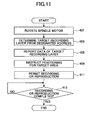
- the flowchart of Fig.11 shows an algorithm including a series of steps executed by the CPU 40.
- the operation of the CPU 40 Upon receiving a recording command or a reproduction command from the upper apparatus 90 (hereinafter also referred to as "command"), the operation of the CPU 40 is started by setting a header address of the program corresponding to the flowchart shown in Fig.11 in a program counter of the CPU 40.
- Step S401 the CPU 40 instructs the drive control circuit 26 to rotate the optical disc 15 at a predetermined linear (or angular speed).
- the CPU 40 also reports the reception of the command from the upper apparatus 90 to the reproduction signal process circuit 28.
- Step S403 the CPU 40 extracts a designated address from the command, and identifies the target recording layer (determines whether it is the first recording layer L0 or the second recording layer L1) based on the designated address.
- Step S405 the CPU 40 reports information regarding the identified target recording layer to, for example, the drive control circuit 26.
- Step S409 the CPU 40 instructs the drive control circuit 26 to form a beam spot in the vicinity of a target area corresponding to the designated address. Thereby, the seek operation is executed. If it is unnecessary to execute the seek operation, the processes in Step S409 may be skipped.
- Step S411 the CPU 40 allows recording of data or reproduction of data in accordance with the command.
- Step S413 the CPU 40 determines whether the recording process or the reproduction process is completed. If the recording process or the reproduction process is not completed, the CPU 40 determines that the completion of the recording process or the reproduction process as negative and reattempts the determination after a predetermined time elapses. If the recording process or the reproduction process is completed, the CPU 40 determines that the completion of the recording process or the reproduction process as affirmative, to thereby end the operation.
- the- optical pickup apparatus 23 provides a light source 51 for irradiating a linearly polarized beam, a grating 200 for diffracting the linearly polarized beam irradiated from the light source 51 to plural bundles of rays, an objective lens 60 for condensing the plural bundles of rays to a target recording layer included in the plural recording layers of the optical disc 15, a 1/4 wave-plate 55 situated on an optical path between the grating 200 and the objective lens 60 for adding an optical phase difference of 1/4 wavelength to incident bundle of rays, the optical system 70 situated on an optical path of the bundle of rays reflected from the optical disc 15 and transmitted through the objective lens 60 and the 1/4 wave-plate 55, and a photo-detector PD for receiving the bundle of rays from the optical system 70 and generating signals according to the amount of light of the received bundle of rays.
- a light source 51 for irradiating a linearly polarized beam
- a grating 200 for diffracting the linearly
- the optical system 70 provides a polarization beam splitter 54 situated on an optical path of the reflected bundle of rays for splitting the reflected bundle of rays, a lens 61 situated in back of the polarization beam splitter 54 for condensing the reflected bundle of rays, a polarization converting optical element 192 situated between a first imaginary plane and a second imaginary plane, the first imaginary plane including condensing areas at which the plural signal beams are condensed by the lens 61, the second imaginary plane including condensing areas at which the plural stray beams are condensed by the lens 61, the polarization converting optical element 192 having plural divided areas for dividing the plural signal beams and the plural stray beams into two bundle of rays and converting polarization of the divided bundle of rays so that one of the divided bundle of rays has a polarization different from the other divided bundle of rays, another polarization converting optical element 193 situated between the first imaginary plane and a
- the reproduction signal process circuit 28, the CPU 40, and the program executed by the CPU 40 are included in a process apparatus according to an embodiment of the present invention. Moreover, the processes (steps) executed by the CPU 40 may also be partly or entirely executed using other additional hardware.
- the bundle of linearly polarized rays (in this example, P polarized light) irradiated from the light source unit 51 is condensed to form plural fine beam spots on the target recording layer of the optical' disc 15 via the coupling lens 52, the grating 200, the polarization beam splitter 54, the 1/4 wave plate 55, and the objective lens 60.
- the reflected bundle of rays (including plural signal lights and plural stray lights) reflected from the optical disc 15 is made into linearly polarized light (in this example, S polarized light) that perpendicularly intersects the direction of the rays irradiated from the light source unit 51 and is incident on the polarization beam splitter 54.
- the bundle of rays reflected in the -Z direction in the polarization beam splitter 54 becomes converged light at the lens 61 (condensing optical element) and is incident on the polarization converting optical element 192.
- the bundle of rays incident on the areas 192a, 192c, and 192e is retarded by -1/4 wavelength and the bundle of rays incident on the areas 192b, 192d, and 192f is retarded by +1/4 wavelength.
- the reflected bundle of rays transmitted through the polarization converting optical element 192 is incident on the polarization converting optical element 193.
- the bundle of rays incident on the areas 193a, 193c, and 193e is retarded by +1/4 wavelength and the bundle of rays incident on the areas 193b, 193d, and 193f is retarded by -1/4 wavelength.
- the plural signal beams transmitted through the polarization converting optical element 193 become P polarized beams and the plural stray beams transmitted through the polarization converting optical element 193 remain S polarized beams.
- the reflected bundle of rays transmitted through the polarization converting optical element 193 is incident on the analyzer 64.
- the optical system 70 extracts plural signal beams from the reflected bundle of rays including plural signal beams and plural stray beams.
- the reflected bundle of rays transmitted through the analyzer 64 is received by the photo-detector PD via the condenser lens 58.
- the borderline which separates (divides) each polarization converting optical element into an area adding retardation of +1/4 wavelength and an area adding retardation of -1/4 wavelength, can be oriented in the same direction as the tracking direction. Therefore, even if the objective lens 60 is shifted in the tracking direction, signal beams and stray beams can be precisely separated.
- photo-electric conversion signals having a high S/N ratio can be output from the optical pickup apparatus 23.
- an optical disc having plural recording layers can be steadily precisely accessed.
- information can be precisely reproduced from an optical disc having plural recording layers.
- each of the areas 192a, 192c, and 192e adds retardation of -1/4 wavelength to the incident bundle of rays and each of the areas 192b, 192d, and 192f adds retardation of +1/4 wavelength to the incident bundle of rays.
- each of the areas 193a, 193c, and 193e adds retardation of +1/4 wavelength to the incident bundle of rays and each of the areas 193b, 193d, and 193f adds retardation of -1/4 wavelength to the incident bundle of rays.
- each of the areas 192a, 192c, and 192e may add retardation of +1/4 wavelength to the incident bundle of rays and each of the areas 192b, 192d, and 192f may add retardation of -1/4 wavelength to the incident bundle of rays.
- each of the areas 193a, 193c; and 193e may add retardation of -1/4 wavelength to the incident bundle of rays and each of the areas 193b, 193d, and 193f adds retardation of +1/4 wavelength to the incident bundle of rays.
- only signal beams can be converted to P polarized beams.
- each of the areas 193a, 193c, and 193e adds retardation of +1/4 wavelength to the incident bundle of rays and each of the areas 193b, 193d, and 193f adds retardation of -1/4 wavelength to the incident bundle of rays
- each of the areas 193a, 193c, and 193d may add retardation of -1/4 wavelength to the incident bundle of rays
- each of the areas 193b, 193d, and 193f may add retardation of +1/4 wavelength to the incident bundle of rays.
- the polarization converting optical elements 192 and 193 can be configured the same. It is, however, to be noted that the analyzer 64 is to allow transmittance of S polarized beams since plural signal beams remain S polarized beams and plural stray beams are converted P polarized beams in this case.
- each of the areas 192a, 192c, and 192e adds retardation of -1/4 wavelength to the incident bundle of rays and each of the areas 192b, 192d, and 192f adds retardation of +1/4 wavelength to the incident bundle of rays.
- each of the areas 192a, 192c, and 192e may add retardation of +1/4 wavelength to the incident bundle of rays and each of the areas 192b, 192d, and 192f may add retardation of -1/4 wavelength to the incident bundle of rays.
- the polarization converting optical elements 192 and 193 can be configured the same. It is, however, to be noted that the analyzer 64 is to allow transmittance of S polarized beams since plural signal beams remain S polarized beams and plural stray beams are converted P polarized beams in this case.
- a polarization converting optical element 292 may be divided into four areas (292a, 292b, 292c, 292d) by three dividing lines (292i, 292k, 292m) extending in the Y axis direction (See Fig.12 ), so that each of the areas 292a and 292c adds retardation of +1/4 wavelength to the incident bundle of rays and each of the areas 292b and 292d adds retardation of -1/4 wavelength to the incident bundle of rays.
- +1 st order beams are incident on the areas 292a and 292b
- 0 th order beams are incident on the areas 292b and 292c
- -1 st order beams are incident on the areas 292c and 292d.
- a polarization converting optical element 293 may be divided into four areas (293a, 293b, 293c, 293d) by three dividing lines (293i, 293k, 293m) extending in the Y axis direction (See Fig.13 ), so that each of the areas 293a and 293c adds retardation of -1/4 wavelength to the incident bundle of rays and each of the areas 293b and 293d adds retardation of +1/4 wavelength to the incident bundle of rays.
- only plural signal are converted to P polarized beams.
- a polarization concerting optical element 294 may be divided into six areas (294a, 294b, 294c, 294d, 294e, 294f) by five dividing lines (294i, 294j, 294k, 2941, 294m) extending in the Y axis direction (See Fig.14 ), so that each of the areas 294a, 294c, and 293e adds retardation of 1/2 wavelength to the incident bundle of rays and each of the areas 294b, 294d, and 294f adds no retardation to the incident bundle of rays.
- +1 st order beams are incident on the areas 294a and 294b
- 0 th order beams are incident on the areas 294c and 294d
- -1 st order beams are incident on the areas 294e and 294f.
- a polarization converting optical element 295 may be divided into six areas (295a, 295b, 295c, 295d, 295e, 295f) by five dividing lines (295i, 295j, 295k, 2951, 295m) extending in the Y axis direction (See Fig.15 ), so that each of the areas 295a, 295c, and 295e adds retardation of 1/2 wavelength to the incident bundle of rays and each of the areas 295b, 295d, and 295f adds no retardation to the incident bundle of rays.
- only plural signal are converted to P polarized beams.
- each of the polarization converting optical elements can have a simplified divided structure, to thereby obtain a polarization converting element of high productivity.
- the polarization converting optical element 294 can be fabricated by dividing a single waveplate capable of adding retardation of 1/2 wavelength into six areas and removing (e.g., etching) the surface corresponding to the areas 294b, 294d, and 294f for eliminating the retarding effects of the areas 294b, 294d, and 294f.
- the polarization converting optical element 294 can be fabricated by dividing a single waveplate capable of adding retardation of 1/2 wavelength into six areas and removing (e.g., etching) the surface corresponding to the areas 295b, 295d, and 295f for eliminating the retarding effects of the areas 295b, 295d, and 295f.
- a polarization concerting optical element 296 may be divided into six areas (296a, 296b, 296c, 296d, 296e, 296f) by five dividing lines (296i, 296j, 296k, 2961, 296m) extending in the Y axis direction (See Fig.16 ), so that each of the areas 296a, 296c, and 296e rotates the polarization (vibration) of the incident bundle of rays +45 degrees and each of the areas 296b, 296d, and 296f rotates the polarization (vibration) of the incident bundle of rays -45 degrees.
- +1 st order beams are incident on the areas 296a and 296b
- 0 th order beams are incident on the areas 296c and 296d
- -1 st order beams are incident on the areas 296e and 296f.
- a polarisation concerting optical element 297 may be divided into six areas (297a, 297b, 297c, 297d, 297e, 297f) by five dividing lines (297i, 297j, 297k, 2971, 297m) extending in the Y axis direction (See Fig.17 ), so that each of the areas 297a, 297c, and 297e rotates the polarization (vibration) of the incident bundle of rays -45 degrees and each of the areas 297b, 297d, and 297f rotates the polarization (vibration) of the incident bundle of rays +45 degrees.
- the same as the above-described embodiments of the present invention only plural signals are converted to P polarized beams.
- the polarization converting optical element 192 and the polarization converting optical element 193 may be combined into a united body via a transparent material having refractivity (index of refraction) greater than 1 (see Fig.18 ). This allows the positions of the polarization converting optical element 192 and the polarization converting optical element 193 to be defined more easily.
- the dividing lines (192i, 192j, 192k, 1921, 192m) of the polarization converting optical element 192 and the dividing lines (193i, 193j, 193k, 1931, 193m) of the polarization converting optical element 193 can easily be positioned facing each other during a manufacturing process, to thereby simplify assembly procedures (steps) and adjustment procedures (steps).
- the polarization converting optical element 192 and the polarization converting optical element 193 are fabricated so that each area (192a, 192b, 192c, 192d, 192e, 192f) of the polarization converting optical element 192 and each area (193a, 193b, 193c, 192d, 192e, 192f) of the polarization converting optical element 193 are appropriately positioned on the transparent material 194, it is preferable to use a sub-wavelength grating or a photonic crystal as the transparent material 194.
- the condensing optical element according to the above-described embodiment of the present invention is explained as being positioned behind (after) the polarizer, the condensing optical element may be positioned in front of (before) the polarizer.
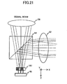
- the lens 58 and the photo-detector PD may be positioned on the -Z side of the polarization beam splitter 54 while a polarization converting optical element 197 and a mirror 65 are used (positioned on the +Z side of the polarization beam splitter 54) instead of using the above-described polarization converting optical element 192, the polarization converting optical element 193, and the analyzer 64 (See Fig.19 ).
- the coupling lens 52 can serve as the condensing optical element, the above-described lens 61 would not be required in this embodiment of the present invention.
- an optical system according to this embodiment of the present invention comprises the polarization beam splitter 54, the coupling lens 52, the polarization converting optical element 197, and the mirror 65.
- the polarization converting optical element 197 is located on the +Z side of the polarization beam splitter and interposed between the condensing plane of plural signal beams and the condensing plane of plural stray beams situated on the -Z side of the condensing plane of the plural signal beams.
- the polarization converting optical element 197 may be divided into, for example, four areas (197a, 197b, 197c, 197d) by three dividing lines (197e, 197f, 197g) extending in the Y axis direction. In this example, each dividing line splits the plural signal beams into two at their corresponding optical axes.
- each of the areas 197a and 197c adds no retardation to the incident bundle of rays and each of the areas 197b and 197d adds retardation of 1/2 wavelength to the incident bundle of rays.
- the areas 197a-197d are provided in a stripe-like configuration having the optical axis of each bundle of rays as a border such that an area adding 1/2 wavelength and an area adding no retardation are alternately arranged. It is to be noted that, when the objective lens 60 shifts in the tracking direction, the reflected bundle of rays incident on the polarization converting optical element 197 shifts in a direction corresponding to the tracking direction (in this example, Y axis direction).
- +1 st order beams of the signal and stray beams are incident on the areas 197a and 197b
- 0 th order beams of the signal and stray beams are incident on the areas 197b and 197c
- -1 st order beams of the signal and stray beams are incident on the areas 197c and 197d.
- a twisted nematic liquid crystal, a sub-wavelength wire-grid, or a photonic crystal may be used for forming the areas 197b and 197d.
- the mirror 65 is situated at the condensing plane of the plural signal beams (see Fig.21 ). Accordingly, the mirror 65 reflects the +1 st order signal beams transmitted through the area 197a to the area 197b and reflects the +1 st order signal beams transmitted through the area 197b to the area 197a. Furthermore, the mirror 65 reflects the 0 th order signal beams transmitted through the area 197b to the area 197c and reflects the 0 th order signal beams transmitted through the area 197c to the area 197b. Furthermore, the mirror 65 reflects the -1 st order beams transmitted through the area 197c to the area 197d and reflects the -1 st order signal beams transmitted through the area 197d to the area 197c.
- Plural signal beams and plural stray beams reflected from the optical disc 15 are converged to the coupling lens 52 and directed in the +Z direction by the polarization beam splitter 54.
- the bundles of rays of the plural signal beams and the plural stray beams are S polarized beams. Then, the plural signal beams and plural stray beams are incident on the polarization converting optical element 197.
- the area 197a adds no retardation to incident +1 st order beams of the signal beams and the area 197b adds retardation of 1/2 to incident +1 st order beams of the signal beams. Then, the +1 st order beams of the signal beams transmitted through the area 197a are reflected by the mirror 65 to the area 197b and the +1 st order beams of the signal beams transmitted through the area 197b are reflected by the mirror 65 to the area 197a. Accordingly, the +1 st order beams of the signal beams reflected by the mirror 65 and transmitted again through the polarization converting optical element 197 all have added retardation of 1/2 wavelength.
- the area 197b adds retardation of 1/2 wavelength to incident 0 th order beams of the signal beams and the area 197c adds no retardation to incident 0 th order beams of the signal beams.
- the 0 th order beams of the signal beams transmitted through the area 197c are reflected by the mirror 65 to the area 197c and the 0 th order beams of the signal beams transmitted through the area 197c are reflected by the mirror 65 to the area 197b.
- the 0 th order beams of the signal beams reflected by the mirror 65 and transmitted again through the polarization converting optical element 197 all have added retardation of 1/2 wavelength.
- the area 197c adds no retardation to incident -1 st order beams of the signal beams and the area 197d adds retardation of 1/2 to incident -1 st order beams of the signal beams.
- the -1 st order beams of the signal beams transmitted through the area 197c are reflected by the mirror 65 to the area 197d and the -1 st order beams of the signal beams transmitted through the area 197d are reflected by the mirror 65 to the area 197c.
- the -1 st order beams of the signal beams reflected by the mirror 65 and transmitted again through the polarization converting optical element 197 all have added retardation of 1/2 wavelength.
- the plural signal beams all become P polarized beams.
- plural stray beams reflected from a recording layer located toward the +X side of the target recording layer are condensed between the polarization beam splitter 54 and the polarization converting optical element 197 and then directed incident onto the polarization converting optical element 197.
- the area 197a adds no retardation to incident +1 st order beams of the stray beams and the area 197b adds retardation of 1/2 to incident +1 st order beams of the stray beams. Then, the +1 st order beams of the stray beams transmitted through the area 197a are reflected by the mirror 65 to the area 197a and the +1 st order beams of the signal beams transmitted through the area 197b are reflected by the mirror 65 to the area 197b (See Fig.22 ). Accordingly, the +1 st order beams of the stray beams reflected by the mirror 65 and transmitted again through the polarization converting optical element 197 do not have retardation added.
- the area 197b adds retardation of 1/2 wavelength to incident 0 th order beams of the stray beams and the area 197c adds no retardation to incident 0 th order beams of the stray beams. Then, the 0 th order beams of the stray beams transmitted through the area 197b are reflected by the mirror 65 to the area 197b and the 0 th order beams of the signal beams transmitted through the area 197c are reflected by the mirror 65 to the area 197c (See Fig.22 ). Accordingly, the 0 th order beams of the stray beams reflected by the mirror 65 and transmitted again through the polarization converting optical element 197 do not have retardation added.
- the area 197c adds no retardation to incident -1 st order beams of the stray beams and the area 197d adds retardation of 1/2 to incident -1 st order beams of the stray beams. Then, the -1 st order beams of the stray beams transmitted through the area 197c are reflected by the mirror 65 to the area 197c and the -1 st order beams of the stray beams transmitted through the area 197d are reflected by the mirror 65 to the area 197c. Accordingly, the -1 st order beams of the stray beams reflected by the mirror 65 and transmitted again through the polarization converting optical element 197 do not have retardation added.
- the plural stray beams reflected from a recording layer located toward the +X side of the target recording layer all remain S polarized beams.
- plural stray beams reflected from a recording layer located toward the -X side of the target recording layer are transmitted through the polarization converting optical element 197 and reach the mirror 65 before condensing. Then, the plural stray beams reflected by the mirror 65 are condensed after transmitting again through the polarization converting optical element 197.
- the area 197a adds no retardation to incident +1 st order beams of the stray beams and the area 197b adds retardation of 1/2 to incident +1 st order beams of the stray beams. Then, the +1 st order beams of the stray beams transmitted through the area 197a are reflected by the mirror 65 to the area 197a and the +1 st order beams of the signal beams transmitted through the area 197b are reflected by the mirror 65 to the area 197b (See Fig.23 ). Accordingly, the +1 st order beams of the stray beams reflected by the mirror 65 and transmitted again through the polarization converting optical element 197 do not have retardation added.
- the area 197b adds retardation of 1/2 wavelength to incident 0 th order beams of the stray beams and the area 197c adds no retardation to incident 0 th order beams of the stray beams. Then, the 0 th order beams of the stray beams transmitted through the area 197b are reflected by the mirror 65 to the area 197b and the 0 th order beams of the signal beams transmitted through the area 197c are reflected by the mirror 65 to the area 197c (See Fig.23 ). Accordingly, the 0 th order beams of the stray beams reflected by the mirror 65 and transmitted again through the polarization converting optical element 197 do not have retardation added.
- the area 197c adds no retardation to incident -1 st order beams of the stray beams and the area 197d adds retardation of 1/2 to incident -1 st order beams of the stray beams. Then, the -1 st order beams of the stray beams transmitted through the area 197c are reflected by the mirror 65 to the area 197c and the -1 st order beams of the stray beams transmitted through the area 197d are reflected by the mirror 65 to the area 197c (See Fig.23 ). Accordingly, the -1 st order beams of the stray beams reflected by the mirror 65 and transmitted again through the polarization converting optical element 197 do not have retardation added.
- the plural stray beams reflected from a recording layer located toward the -X side of the target recording layer all remain S polarized beams.
- plural signal beams are converted to P polarized beams and plural stray beams remain S polarized beams.
- the bundle of rays reflected from the mirror 65 and transmitted again through the polarization converting optical element 197 are incident on the polarization beam splitter 54. Only P polarized beams are transmitted through the polarization beam splitter 54 and are incident on the condenser lens 58. Thereby, the bundle of rays incident on the photo-detector includes plural signal beams only. Accordingly, the same effects can be attained as those of the above-described embodiments of the present invention. Thus, the number of components of the optical pickup can be reduced and the size of the optical pickup apparatus can be reduced.
- the optical system 70 includes: the polarization beam splitter 54 located on the optical path of the reflected bundle of rays for splitting the reflected bundle of rays; the coupling lens 52 located in front of the polarization beam splitter 54 for condensing the reflected bundle of rays; the polarization converting optical element 197 located between a first imaginary plane that includes condensing areas of plural signal beams condensed by the coupling lens 52 and a second imaginary plane that is located more toward the coupling lens 52 than the first imaginary plane and includes condensing areas of plural stray beams condensed by the coupling lens 52, the polarization converting optical element 197 splitting plural signal beams and plural stray beams into two bundle of rays and controlling the polarization of the split bundle of rays so that one of the split bundle of rays has a different polarization than the other split bundle of rays; and a mirror 65 located on the first imaginary plane for reflecting the reflected bundle of rays transmitted through the polar
- each dividing line of the polarization converting optical element 197 matches the direction corresponding to the tracking direction, plural signal beams and plural stray beams can be precisely separated even when the objective lens shifts in the tracking direction.
- the polarization converting optical element 197 and the mirror 65 may be formed as a united body.
- the polarization converting optical element 197 and the mirror 65 may be formed as a united body by using a transparent material having refractivity greater than 1.
- the optical axes of the ⁇ 1 st order beams diffracted at the grating 200 are inclined with respect to the optical axis of the 0 th order beam.
- the orientation of the normal line of the reflecting plane of the mirror 65 for reflecting the 0 th order beam matches the orientation of the optical axis of the 0 th order beam
- the orientation of the normal line of the reflecting plane of the mirror 65 for reflecting the +1 st order beam matches the orientation of the optical axis of the +1 st order beam
- the orientation of the normal line of the reflecting plane of the mirror 65 for reflecting the -1 st order beam matches the orientation of the optical axis of the -1 st order beam.
- the reflecting planes of the +1 st order beam and the -1 st order beam may be inclined with respect to the reflecting plane of the 0 th order beam.
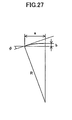
- the reflecting plane of the mirror 65 may be curved so that the orientation of the normal line of a reflecting part of the mirror 65 for reflecting the 0 th order beam substantially matches the orientation of the optical axis of the 0 th order beam, the orientation of the normal line of a reflecting part of the mirror 65 for reflecting the +1 st order beam substantially matches the orientation of the optical axis of the +1 st order beam, and the orientation of the normal line of the reflecting part of the mirror 65 for reflecting the -1 st order beam substantially matches the orientation of the optical axis of the -1 st order.
- the amount of sag "b" may be set to satisfy a relationship where "b” is no less than R ⁇ ⁇ 1-cos ( ⁇ ) ⁇ .
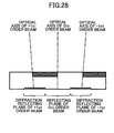
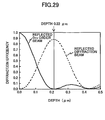
- a diffraction grating may be formed at a reflecting plane of the mirror 65 corresponding to the +1 st order beam and another diffraction grating may be formed at another reflecting plane of the mirror 65 corresponding to the -1 st order beam so that the orientation of an optical axis of an ingoing beam matches the orientation of an optical axis of an outgoing beam.
- the dividing lines which divide the polarization converting optical element 197 into plural areas may.include a dividing line 197f intersecting with the optical axis of the 0 th order beam, a dividing line 197e extending between the optical axis of the +1 st order beam incident (incoming) on the polarization converting optical element 197 and the optical axis of the +1 st order beam reflected from the mirror 65 and emitted (outgoing) from the polarization converting optical element 197, and a dividing line extending between the optical axis of the -1 st order beam and the -1 st order beam reflected from the mirror 65 and emitted (outgoing) from the polarization converting optical element 197.
- the optical system 70' according to the above-described embodiment of the present invention is explained as having the condensing optical element positioned in front of (before) the polarizer, the condensing optical element may be positioned before (after) the polarizer.
- the above-described embodiments of the present invention explain a case of irradiating three bundle of rays (beams) to the optical disc for obtaining push-pull signals according to, the same effects can be attained in a case of irradiating, for example, five or seven beams by increasing the number of divided areas of the polarization converting optical element in correspondence with the number of bundle of rays (beams) irradiated to the optical disk.
- optical disc apparatus 20 according to an embodiment of the present invention is described above as an apparatus that can record and reproduce information to/from the optical disc 15, the optical disc apparatus 20 includes other optical apparatuses as long as the apparatus can at least reproduce information of an optical disc.
- the optical discs 15 is described as having two layers, the optical disc 15 is not limited to having two layers.
- the optical disc 15 may alternatively have three or more layers.
- the bundle of reflected beams include plural stray light beams (first stray light) which condense at a position closer to the focus point of plural signal light beams and additional plural stray light beams (second stray light) which condense at a position farther from the focus point of the plural signal light beams. Even in this case, plural signal light beams can be extracted.
- the optical disc 15 according to an embodiment of the present invention includes not only DVD type optical discs, but also CD type optical discs and next generation information recording media corresponding to a light beam having a wavelength of approximately 405 nm.
- the optical pickup apparatus 23 is described using an example of a single semiconductor laser, plural lasers may also be employed.
- multiple semiconductor lasers that emit beams of different wavelengths may be used.
- one semiconductor laser may emit a beam having a wavelength of approximately 405 nm
- another semiconductor laser may emit a beam having a wavelength of approximately 660 nm
- yet another semiconductor laser may emit a beam having a wavelength of approximately 780 nm.
- the optical disc apparatus 20 includes an optical disc apparatus that is compatible with various optical discs of different standards, in which one of the optical discs may be an optical disc having plural recording layers.
- the differential push-pull signals of a conventional optical system exhibit irregular signal amplitude due to the influence of stray light
- the differential push-pull signals of the optical system according to an embodiment of the present invention exhibit satisfactory sine wave amplitude.
- plural signal light beams can be efficiently extracted from a bundle of rays including plural signal beams and stray beams.
- desired signals can be precisely obtained from an optical disc having plural recording layers.
- an optical disc having plural recording layers can be steadily precisely accessed.
Landscapes
- Physics & Mathematics (AREA)
- Optics & Photonics (AREA)
- Chemical & Material Sciences (AREA)
- Crystallography & Structural Chemistry (AREA)
- Mathematical Physics (AREA)
- Optical Head (AREA)
Abstract
Claims (12)
- Système optique (70) pour extraire une pluralité de faisceaux de signaux d'un faisceau de rayons réfléchi par un disque optique multicouche (15), le faisceau de rayons réfléchi comprenant la pluralité de faisceaux de signaux comprenant des faisceaux réfléchis par une couche cible et une pluralité de faisceaux parasites comprenant des faisceaux réfléchis par les couches d'enregistrement à côté de la couche d'enregistrement cible, chacun des faisceaux de signaux et des faisceaux parasites comprenant un faisceau d'ordre 0, un faisceau d'ordre +1 et un faisceau d'ordre -1 générés par un réseau de diffraction (200), le système optique comprenant :un polariseur (54) situé sur un trajet optique du faisceau de rayons réfléchi pour diviser le faisceau de rayons réfléchi ;un élément optique condensateur (61) situé à l'avant ou à l'arrière du polariseur pour condenser le faisceau de rayons réfléchi ;un premier élément optique de conversion de polarisation (192) situé entre un premier plan d'image et un deuxième plan d'image, le premier plan d'image comprenant des zones de condensation au niveau desquelles la pluralité de faisceaux de signaux sont condensés par l'élément optique condensateur (61), le deuxième plan d'image comprenant des zones de condensation au niveau desquelles la pluralité de faisceaux parasites sont condensés par l'élément optique condensateur (61), le premier élément optique de conversion de polarisation (192) comportant une pluralité de zones divisées par une pluralité de lignes de division parallèles, la pluralité de zones ayant des caractéristiques de polarisation associées de sorte que la pluralité de zones retardent respectivement la phase optique du faisceau de rayons incident alternativement de +1/4 de longueur d'onde et de -1/4 de longueur d'onde ou, en variante, que la pluralité de zones retardent respectivement la phase optique du faisceau de rayons incident alternativement de 0 longueur d'onde et de +1/2 longueur d'onde, ou en tant qu'autre variante, que la pluralité de zones fassent respectivement tourner la polarisation du faisceau de rayons incident alternativement de +45 degrés et de -45 degrés, le premier élément optique de conversion de polarisation étant agencé pour diviser les faisceaux d'ordre 0, les faisceaux d'ordre +1 et les faisceaux d'ordre -1 de la pluralité de faisceaux de signaux et de la pluralité de faisceaux parasites en deux ensembles de rayons en fonction de la pluralité de zones divisées par la pluralité de lignes de division parallèles et convertir la polarisation du faisceau divisé des ensembles en fonction des caractéristiques de polarisation associées de sorte que l'un des ensembles de rayons divisés ait une polarisation différente de celle de l'autre des ensembles de rayons divisés ;un deuxième élément optique de conversion de polarisation (193) situé entre le premier plan d'image et un troisième plan d'image situé plus loin de l'élément optique condensateur (61) que le premier plan d'image, le troisième plan d'image comprenant des zones de condensation au niveau desquelles la pluralité de faisceaux parasites sont condensés, le deuxième élément optique de conversion de polarisation (193) comportant une pluralité de zones divisées par une pluralité de lignes de division parallèles, la pluralité de zones ayant des caractéristiques de polarisation associées de sorte que la pluralité de zones retardent respectivement la phase optique du faisceau de rayons incident alternativement de +1/4 de longueur d'onde et de -1/4 de longueur d'onde ou, en variante, que la pluralité de zones retardent respectivement la phase optique du faisceau de rayons incident alternativement de 0 longueur d'onde et de +1/2 longueur d'onde, ou en tant qu'autre variante, que la pluralité de zones fassent respectivement tourner la polarisation du faisceau de rayons incident alternativement de +45 degrés et de -45 degrés et faisant face à la pluralité de zones divisées du premier élément optique de conversion de polarisation pour convertir la polarisation des faisceaux d'ordre 0, des faisceaux d'ordre +1 et des faisceaux d'ordre -1 de la pluralité de faisceaux de signaux et de la pluralité de faisceaux parasites transmis par l'intermédiaire du premier élément optique de conversion de polarisation en fonction des caractéristiques de polarisation associées de sorte que la pluralité de faisceaux de signaux aient une polarisation différente de celle de la pluralité de faisceaux parasites ; etun analyseur (64) pour extraire la pluralité de faisceaux de signaux du faisceau de rayons réfléchi transmis par l'intermédiaire du deuxième élément optique de conversion de polarisation (193) sur la base de la différence de polarisation.
- Système optique (70) selon la revendication 1, dans lequel les premier et deuxième éléments optiques de conversion de polarisation (192, 193) ont les mêmes caractéristiques optiques.
- Système optique (70) selon la revendication 1, dans lequel les premier et deuxième éléments optiques de conversion de polarisation (192, 193) sont formés en tant que corps uni par un matériau transparent ayant un indice de réfraction supérieur à 1.
- Système optique (70') pour extraire une pluralité de faisceaux de signaux d'un faisceau de rayons réfléchi par un disque optique multicouche (15), le faisceau de rayons réfléchi comprenant la pluralité de faisceaux de signaux comprenant des faisceaux réfléchis par une couche cible et une pluralité de faisceaux parasites comprenant des faisceaux réfléchis par les couches d'enregistrement à côté de la couche cible, chacun des faisceaux de signaux et des faisceaux parasites comprenant un faisceau d'ordre 0, un faisceau d'ordre +n et un faisceau d'ordre -n générés par un réseau de diffraction (200), où n est un entier supérieur ou égal à 1, le système optique comprenant :un polariseur (54) situé sur un trajet optique du faisceau de rayons réfléchi pour diviser le faisceau de rayons réfléchi ;un élément optique condensateur (52) situé à l'avant ou à l'arrière du polariseur (54) pour condenser le faisceau de rayons réfléchi ;un élément optique de conversion de polarisation (197) situé entre un premier plan d'image et un deuxième plan d'image, le premier plan d'image comprenant des zones de condensation au niveau desquelles la pluralité de faisceaux de signaux sont condensés par l'élément optique condensateur (52), le deuxième plan d'image comprenant des zones de condensation au niveau desquelles la pluralité de faisceaux parasites sont condensés par l'élément optique condensateur (52), l'élément optique de conversion de polarisation (197) comportant une pluralité de zones divisées par une pluralité de lignes de division parallèles, la pluralité de zones ayant des caractéristiques de polarisation associées de sorte que la pluralité de zones retardent respectivement la phase optique du faisceau de rayons incident alternativement de 0 longueur d'onde et de +1/2 longueur d'onde, le premier élément optique de conversion de polarisation étant agencé pour diviser les faisceaux d'ordre 0, les faisceaux d'ordre +n et les faisceaux d'ordre -n de la pluralité de faisceaux de signaux et de la pluralité de faisceaux parasites en deux ensembles de rayons en fonction de la pluralité de zones divisées par la pluralité de lignes de division parallèles et convertir la polarisation des ensembles de rayons divisés en fonction des caractéristiques de polarisation associées de sorte que l'un des ensembles de rayons divisés ait une polarisation différente de celle de l'autre des ensembles de rayons divisés ; etun élément de réflexion (65) situé dans le premier plan d'image pour réfléchir le faisceau de rayons réfléchi transmis par l'intermédiaire de l'élément optique de conversion de polarisation vers l'élément optique de conversion de polarisation (197) ;dans lequel le faisceau de rayons réfléchi qui est réfléchi par l'élément de réflexion (65) frappe le polariseur (54) et la pluralité de faisceaux de signaux sont extraits de celui-ci sur la base de la différence de polarisation par le polariseur.
- Système optique (70') selon la revendication 4, dans lequel l'élément optique de conversion de polarisation (197) et l'élément de réflexion sont formés en tant que corps uni par un matériau transparent ayant un indice de réfraction supérieur à 1.
- Système optique (70') selon la revendication 4, dans lequel la pluralité de zones divisées sont divisées par une pluralité de lignes de division, dans lequel la pluralité de lignes de division comprennent une ligne de division croisant un axe optique du faisceau d'ordre 0, une ligne de division s'étendant entre un axe optique du faisceau d'ordre +n frappant l'élément optique de conversion de polarisation (197) et un autre axe optique du faisceau d'ordre +n réfléchi par l'élément de réflexion et émis par l'élément optique de conversion de polarisation (197), et une ligne de division s'étendant entre un axe optique du faisceau d'ordre -n et un autre axe optique du faisceau d'ordre -n réfléchi par l'élément de réflexion (65) et émis par l'élément optique de conversion de polarisation (197).
- Système optique (70') selon la revendication 4, dans lequel l'élément de réflexion (65) comprend un premier plan de réflexion pour réfléchir le faisceau d'ordre 0, un deuxième plan de réflexion pour réfléchir le faisceau d'ordre +n et un troisième plan de réflexion pour réfléchir le faisceau d'ordre -n, dans lequel l'orientation d'une ligne normale du premier plan de réflexion correspond à l'orientation d'un axe optique du faisceau d'ordre 0, l'orientation d'une ligne normale du deuxième plan de réflexion correspond à l'orientation d'un axe optique du faisceau d'ordre +n, et l'orientation d'une ligne normale du troisième plan de réflexion correspond à l'orientation d'un axe optique du faisceau d'ordre-n.
- Système optique (70') selon la revendication 4, dans lequel l'élément de réflexion (65) comprend une première partie de réflexion pour réfléchir le faisceau d'ordre 0, une deuxième partie de réflexion pour réfléchir le faisceau d'ordre +n et une troisième partie de réflexion pour réfléchir le faisceau d'ordre -n, dans lequel l'orientation d'une ligne normale de la première partie de réflexion correspond sensiblement à l'orientation d'un axe optique du faisceau d'ordre 0, l'orientation d'une ligne normale de la deuxième partie de réflexion correspond sensiblement à l'orientation d'un axe optique du faisceau d'ordre +n, et l'orientation d'une ligne normale de la troisième partie de réflexion correspond sensiblement à l'orientation d'un axe optique du faisceau d'ordre -n.
- Système optique (70') selon la revendication 4, dans lequel l'élément de réflexion (65) comprend un premier plan de réflexion pour réfléchir le faisceau d'ordre 0, un deuxième plan de réflexion pour réfléchir le faisceau d'ordre +n et un troisième plan de réflexion pour réfléchir le faisceau d'ordre -n, dans lequel l'orientation d'une ligne normale du premier plan de réflexion correspond à l'orientation d'un axe optique du faisceau d'ordre 0, dans lequel le deuxième plan de réflexion comprend un réseau de diffraction (200) pour mettre en correspondance un axe optique d'un faisceau entrant avec un axe optique d'un faisceau sortant, dans lequel le troisième plan de réflexion comprend un réseau de diffraction pour mettre en correspondance un axe optique d'un faisceau entrant avec un axe optique d'un faisceau sortant.
- Dispositif de lecture optique (23) pour rayonner un faisceau de rayons vers un disque optique (15) comportant une pluralité de couches d'enregistrement et recevoir le faisceau de rayons réfléchi par le disque optique, le dispositif de lecture optique (23) comprenant :une source de lumière (51) pour rayonner un faisceau polarisé linéairement ;un réseau (200) pour diffracter le faisceau polarisé linéairement en une pluralité de faisceaux de rayons ;une lentille de focalisation (60) pour condenser la pluralité de faisceaux de rayons vers une couche d'enregistrement cible incluse dans la pluralité de couches d'enregistrement ;une plaque quart d'onde (55) située sur un trajet optique entre le réseau (200) et la lentille de focalisation (60) pour ajouter une différence de phase optique d'un quart de longueur d'onde au faisceau de rayons incident ;le système optique (70, 70') selon l'une des revendications 1 et 4 situé sur un trajet optique du faisceau de rayons réfléchi par le disque optique (15) et transmis par l'intermédiaire de la lentille de focalisation (60) et de la plaque quart d'onde (55); etun photodétecteur (PD) pour recevoir le faisceau de rayons provenant du système optique (70) et générer des signaux conformément à la quantité de lumière du faisceau de rayons reçu.
- Dispositif de lecture optique (23) selon la revendication 10 lors de l'utilisation du système optique (70) de la revendication 1, dans lequel la pluralité de zones divisées des premier et deuxième éléments optiques de conversion de polarisation (192, 193) dans le système optique (70) sont divisées par une pluralité de lignes de division, dans lequel la pluralité de lignes de division s'étendent dans une direction correspondant à une direction de suivi du dispositif de lecture optique (23).
- Dispositif de disque optique capable au moins de reproduire des informations à partir d'un disque optique (15) comportant une pluralité de couches d'enregistrement, le dispositif de disque optique comprenant :le dispositif de lecture optique (23) selon la revendication 10, etun dispositif de traitement pour reproduire des informations enregistrées sur le disque optique (15) conformément aux signaux délivrés par le photodétecteur (PD) du dispositif de lecture optique (23).
Applications Claiming Priority (4)
| Application Number | Priority Date | Filing Date | Title |
|---|---|---|---|
| JP2006225151 | 2006-08-22 | ||
| JP2007122024 | 2007-05-07 | ||
| JP2007132385A JP4842209B2 (ja) | 2006-08-22 | 2007-05-18 | 抽出光学系、光ピックアップ及び光ディスク装置 |
| PCT/JP2007/066074 WO2008023652A1 (fr) | 2006-08-22 | 2007-08-13 | Système optique, appareil de lecture optique, et appareil à disque optique conçu pour extraire des faisceaux de signaux |
Publications (3)
| Publication Number | Publication Date |
|---|---|
| EP2054888A1 EP2054888A1 (fr) | 2009-05-06 |
| EP2054888A4 EP2054888A4 (fr) | 2009-10-28 |
| EP2054888B1 true EP2054888B1 (fr) | 2011-07-27 |
Family
ID=39106738
Family Applications (1)
| Application Number | Title | Priority Date | Filing Date |
|---|---|---|---|
| EP07792690A Not-in-force EP2054888B1 (fr) | 2006-08-22 | 2007-08-13 | Système optique, appareil de lecture optique, et appareil à disque optique conçu pour extraire des faisceaux de signaux |
Country Status (7)
| Country | Link |
|---|---|
| US (1) | US8064316B2 (fr) |
| EP (1) | EP2054888B1 (fr) |
| JP (1) | JP4842209B2 (fr) |
| KR (1) | KR100914703B1 (fr) |
| CN (1) | CN101356580B (fr) |
| TW (1) | TWI351693B (fr) |
| WO (1) | WO2008023652A1 (fr) |
Families Citing this family (4)
| Publication number | Priority date | Publication date | Assignee | Title |
|---|---|---|---|---|
| JP2008130219A (ja) * | 2006-11-27 | 2008-06-05 | Sanyo Electric Co Ltd | 光ピックアップ装置 |
| JP2011181120A (ja) * | 2010-02-26 | 2011-09-15 | Hitachi Maxell Ltd | コリメートレンズユニット及びそれを用いた光ピックアップ装置 |
| JP5617561B2 (ja) | 2010-11-25 | 2014-11-05 | 株式会社リコー | 撮像装置 |
| JP7293698B2 (ja) | 2019-02-07 | 2023-06-20 | 株式会社リコー | 光学システム、撮像システム及び撮像装置 |
Family Cites Families (14)
| Publication number | Priority date | Publication date | Assignee | Title |
|---|---|---|---|---|
| JP2624255B2 (ja) | 1987-06-09 | 1997-06-25 | オリンパス光学工業株式会社 | 光記録再生装置 |
| JP3266627B2 (ja) * | 1991-10-11 | 2002-03-18 | 株式会社日立製作所 | 情報再生装置 |
| JPH08185640A (ja) * | 1994-12-28 | 1996-07-16 | Sony Corp | 多層光ディスク用光ピックアップ装置 |
| JP3605279B2 (ja) * | 1998-02-25 | 2004-12-22 | パイオニア株式会社 | 光学式ピックアップ |
| JP2002367211A (ja) * | 2001-06-11 | 2002-12-20 | Hitachi Ltd | 光学情報記録再生装置 |
| JP2003323736A (ja) * | 2002-05-01 | 2003-11-14 | Sony Corp | 光ピックアップ及びそれを利用した光記録及び/又は再生装置 |
| KR100965884B1 (ko) * | 2004-01-14 | 2010-06-24 | 삼성전자주식회사 | 광픽업 |
| JP4557281B2 (ja) | 2004-02-16 | 2010-10-06 | 株式会社リコー | 光ピックアップ装置及び光ディスク装置 |
| CN100452199C (zh) * | 2004-04-21 | 2009-01-14 | 松下电器产业株式会社 | 共焦光学系统开口位置检测装置、控制装置、及其检测方法、光学头装置及光信息处理装置 |
| JP4234109B2 (ja) * | 2004-10-18 | 2009-03-04 | 株式会社リコー | 光ピックアップ装置とこれを用いる情報記録装置 |
| JP4264406B2 (ja) * | 2004-10-26 | 2009-05-20 | パルステック工業株式会社 | 光ピックアップ装置 |
| JP4859095B2 (ja) | 2005-03-02 | 2012-01-18 | 株式会社リコー | 抽出光学系、光ピックアップ装置及び光ディスク装置 |
| EP1854098B1 (fr) | 2005-03-02 | 2012-02-29 | Ricoh Company, Ltd. | Systeme optique, dispositif a tete de lecture optique et disque a disque optique |
| JP2008033991A (ja) * | 2006-07-26 | 2008-02-14 | Konica Minolta Opto Inc | 光ピックアップ装置 |
-
2007
- 2007-05-18 JP JP2007132385A patent/JP4842209B2/ja not_active Expired - Fee Related
- 2007-08-13 CN CN2007800014017A patent/CN101356580B/zh not_active Expired - Fee Related
- 2007-08-13 WO PCT/JP2007/066074 patent/WO2008023652A1/fr not_active Ceased
- 2007-08-13 US US12/091,048 patent/US8064316B2/en not_active Expired - Fee Related
- 2007-08-13 KR KR1020087009634A patent/KR100914703B1/ko not_active Expired - Fee Related
- 2007-08-13 EP EP07792690A patent/EP2054888B1/fr not_active Not-in-force
- 2007-08-16 TW TW096130362A patent/TWI351693B/zh not_active IP Right Cessation
Also Published As
| Publication number | Publication date |
|---|---|
| US20100135143A1 (en) | 2010-06-03 |
| EP2054888A1 (fr) | 2009-05-06 |
| CN101356580B (zh) | 2011-03-30 |
| JP2008305442A (ja) | 2008-12-18 |
| EP2054888A4 (fr) | 2009-10-28 |
| JP4842209B2 (ja) | 2011-12-21 |
| TWI351693B (en) | 2011-11-01 |
| KR20080065976A (ko) | 2008-07-15 |
| WO2008023652A1 (fr) | 2008-02-28 |
| CN101356580A (zh) | 2009-01-28 |
| US8064316B2 (en) | 2011-11-22 |
| TW200828297A (en) | 2008-07-01 |
| KR100914703B1 (ko) | 2009-08-28 |
Similar Documents
| Publication | Publication Date | Title |
|---|---|---|
| US7839753B2 (en) | Optical system, optical pickup apparatus, and optical disk apparatus | |
| JP2005203090A (ja) | 光ピックアップ | |
| HK1040813B (zh) | 可兼容不同厚度光盘的物镜 | |
| JP2003294926A (ja) | 波長結合素子及びそれを備えた光ピックアップ装置 | |
| KR100914703B1 (ko) | 신호 빔을 추출하기 위한 광학 시스템, 광 픽업 장치 및 광디스크 장치 | |
| CN1249698C (zh) | 光学扫描装置 | |
| CN100382172C (zh) | 光盘设备,光学拾取器的控制方法和光盘的判别方法 | |
| CN1957404B (zh) | 光学系统、光学拾取装置、和光盘装置 | |
| CN100347771C (zh) | 光盘设备 | |
| JP4925256B2 (ja) | 光源ユニット、光検出ユニット、光ピックアップ装置及び光ディスク装置 | |
| WO2011064992A1 (fr) | Capteur optique et dispositif à disque optique | |
| CN1193360C (zh) | 槽脊/槽识别方法和采用该方法的光记录/再现装置 | |
| JPS59142758A (ja) | 光学的読み取り装置 | |
| JP4568653B2 (ja) | 光ピックアップおよび光情報処理装置 | |
| CN1138263C (zh) | 兼容多种规格盘片的光学头 | |
| CN1430219A (zh) | 多波长的光学读写头 | |
| CN1337682A (zh) | 兼容多种规格盘片的光学拾取器 | |
| HK1032473B (en) | Optical pickup | |
| WO2012144343A1 (fr) | Lentille d'objectif et dispositif de disque optique sur lequel est montée ladite lentille | |
| JP2010079990A (ja) | 光ピックアップ装置およびそれを用いた光ディスク装置 | |
| WO2005048249A1 (fr) | Capteur optique et le lecteur de disques optiques |
Legal Events
| Date | Code | Title | Description |
|---|---|---|---|
| PUAI | Public reference made under article 153(3) epc to a published international application that has entered the european phase |
Free format text: ORIGINAL CODE: 0009012 |
|
| 17P | Request for examination filed |
Effective date: 20080422 |
|
| AK | Designated contracting states |
Kind code of ref document: A1 Designated state(s): AT BE BG CH CY CZ DE DK EE ES FI FR GB GR HU IE IS IT LI LT LU LV MC MT NL PL PT RO SE SI SK TR |
|
| AX | Request for extension of the european patent |
Extension state: AL BA HR MK RS |
|
| DAX | Request for extension of the european patent (deleted) | ||
| RBV | Designated contracting states (corrected) |
Designated state(s): DE FR GB NL |
|
| A4 | Supplementary search report drawn up and despatched |
Effective date: 20090928 |
|
| 17Q | First examination report despatched |
Effective date: 20100804 |
|
| GRAP | Despatch of communication of intention to grant a patent |
Free format text: ORIGINAL CODE: EPIDOSNIGR1 |
|
| RIC1 | Information provided on ipc code assigned before grant |
Ipc: G11B 7/135 20060101AFI20110114BHEP |
|
| GRAS | Grant fee paid |
Free format text: ORIGINAL CODE: EPIDOSNIGR3 |
|
| GRAA | (expected) grant |
Free format text: ORIGINAL CODE: 0009210 |
|
| AK | Designated contracting states |
Kind code of ref document: B1 Designated state(s): DE FR GB NL |
|
| REG | Reference to a national code |
Ref country code: GB Ref legal event code: FG4D |
|
| REG | Reference to a national code |
Ref country code: DE Ref legal event code: R096 Ref document number: 602007016121 Country of ref document: DE Effective date: 20110929 |
|
| REG | Reference to a national code |
Ref country code: NL Ref legal event code: VDEP Effective date: 20110727 |
|
| PG25 | Lapsed in a contracting state [announced via postgrant information from national office to epo] |
Ref country code: NL Free format text: LAPSE BECAUSE OF FAILURE TO SUBMIT A TRANSLATION OF THE DESCRIPTION OR TO PAY THE FEE WITHIN THE PRESCRIBED TIME-LIMIT Effective date: 20110727 |
|
| PLBE | No opposition filed within time limit |
Free format text: ORIGINAL CODE: 0009261 |
|
| STAA | Information on the status of an ep patent application or granted ep patent |
Free format text: STATUS: NO OPPOSITION FILED WITHIN TIME LIMIT |
|
| 26N | No opposition filed |
Effective date: 20120502 |
|
| REG | Reference to a national code |
Ref country code: DE Ref legal event code: R097 Ref document number: 602007016121 Country of ref document: DE Effective date: 20120502 |
|
| REG | Reference to a national code |
Ref country code: FR Ref legal event code: PLFP Year of fee payment: 10 |
|
| PGFP | Annual fee paid to national office [announced via postgrant information from national office to epo] |
Ref country code: DE Payment date: 20160822 Year of fee payment: 10 Ref country code: GB Payment date: 20160819 Year of fee payment: 10 |
|
| PGFP | Annual fee paid to national office [announced via postgrant information from national office to epo] |
Ref country code: FR Payment date: 20160822 Year of fee payment: 10 |
|
| REG | Reference to a national code |
Ref country code: DE Ref legal event code: R119 Ref document number: 602007016121 Country of ref document: DE |
|
| GBPC | Gb: european patent ceased through non-payment of renewal fee |
Effective date: 20170813 |
|
| REG | Reference to a national code |
Ref country code: FR Ref legal event code: ST Effective date: 20180430 |
|
| PG25 | Lapsed in a contracting state [announced via postgrant information from national office to epo] |
Ref country code: DE Free format text: LAPSE BECAUSE OF NON-PAYMENT OF DUE FEES Effective date: 20180301 Ref country code: GB Free format text: LAPSE BECAUSE OF NON-PAYMENT OF DUE FEES Effective date: 20170813 |
|
| PG25 | Lapsed in a contracting state [announced via postgrant information from national office to epo] |
Ref country code: FR Free format text: LAPSE BECAUSE OF NON-PAYMENT OF DUE FEES Effective date: 20170831 |