EP2055185A1 - Überlaufvorrichtung für wassertank - Google Patents
Überlaufvorrichtung für wassertank Download PDFInfo
- Publication number
- EP2055185A1 EP2055185A1 EP07790906A EP07790906A EP2055185A1 EP 2055185 A1 EP2055185 A1 EP 2055185A1 EP 07790906 A EP07790906 A EP 07790906A EP 07790906 A EP07790906 A EP 07790906A EP 2055185 A1 EP2055185 A1 EP 2055185A1
- Authority
- EP
- European Patent Office
- Prior art keywords
- water
- aquarium
- pipe
- suction
- siphon pipe
- Prior art date
- Legal status (The legal status is an assumption and is not a legal conclusion. Google has not performed a legal analysis and makes no representation as to the accuracy of the status listed.)
- Granted
Links
- XLYOFNOQVPJJNP-UHFFFAOYSA-N water Substances O XLYOFNOQVPJJNP-UHFFFAOYSA-N 0.000 title claims abstract description 280
- 230000004044 response Effects 0.000 claims description 2
- 238000001914 filtration Methods 0.000 description 137
- 102000004169 proteins and genes Human genes 0.000 description 34
- 108090000623 proteins and genes Proteins 0.000 description 34
- 239000004575 stone Substances 0.000 description 23
- 239000002023 wood Substances 0.000 description 20
- 239000000463 material Substances 0.000 description 18
- 239000007921 spray Substances 0.000 description 16
- 238000004891 communication Methods 0.000 description 13
- 230000006870 function Effects 0.000 description 13
- 230000007246 mechanism Effects 0.000 description 10
- 238000005507 spraying Methods 0.000 description 9
- 241000251468 Actinopterygii Species 0.000 description 6
- OKTJSMMVPCPJKN-UHFFFAOYSA-N Carbon Chemical compound [C] OKTJSMMVPCPJKN-UHFFFAOYSA-N 0.000 description 6
- 230000000694 effects Effects 0.000 description 6
- 238000009434 installation Methods 0.000 description 6
- 230000002093 peripheral effect Effects 0.000 description 6
- 241000894006 Bacteria Species 0.000 description 5
- 238000011084 recovery Methods 0.000 description 4
- 125000006850 spacer group Chemical group 0.000 description 4
- 230000009931 harmful effect Effects 0.000 description 3
- 238000003780 insertion Methods 0.000 description 3
- 230000037431 insertion Effects 0.000 description 3
- 238000000034 method Methods 0.000 description 3
- 230000004048 modification Effects 0.000 description 3
- 238000012986 modification Methods 0.000 description 3
- 210000002268 wool Anatomy 0.000 description 3
- 230000001580 bacterial effect Effects 0.000 description 2
- 230000000903 blocking effect Effects 0.000 description 2
- 239000000356 contaminant Substances 0.000 description 2
- 230000001186 cumulative effect Effects 0.000 description 2
- 238000007599 discharging Methods 0.000 description 2
- 239000012530 fluid Substances 0.000 description 2
- 230000006978 adaptation Effects 0.000 description 1
- 230000004075 alteration Effects 0.000 description 1
- 239000000470 constituent Substances 0.000 description 1
- 230000007423 decrease Effects 0.000 description 1
- 230000003247 decreasing effect Effects 0.000 description 1
- 230000008030 elimination Effects 0.000 description 1
- 238000003379 elimination reaction Methods 0.000 description 1
- 239000013505 freshwater Substances 0.000 description 1
- 230000014509 gene expression Effects 0.000 description 1
- 230000005484 gravity Effects 0.000 description 1
- 238000012423 maintenance Methods 0.000 description 1
- 238000012856 packing Methods 0.000 description 1
- 239000011148 porous material Substances 0.000 description 1
- 238000002360 preparation method Methods 0.000 description 1
- 230000008439 repair process Effects 0.000 description 1
- 239000011347 resin Substances 0.000 description 1
- 229920005989 resin Polymers 0.000 description 1
- 230000007480 spreading Effects 0.000 description 1
Images




Classifications
-
- A—HUMAN NECESSITIES
- A01—AGRICULTURE; FORESTRY; ANIMAL HUSBANDRY; HUNTING; TRAPPING; FISHING
- A01K—ANIMAL HUSBANDRY; AVICULTURE; APICULTURE; PISCICULTURE; FISHING; REARING OR BREEDING ANIMALS, NOT OTHERWISE PROVIDED FOR; NEW BREEDS OF ANIMALS
- A01K63/00—Receptacles for live fish, e.g. aquaria; Terraria
- A01K63/003—Aquaria; Terraria
- A01K63/006—Accessories for aquaria or terraria
-
- B—PERFORMING OPERATIONS; TRANSPORTING
- B01—PHYSICAL OR CHEMICAL PROCESSES OR APPARATUS IN GENERAL
- B01D—SEPARATION
- B01D2201/00—Details relating to filtering apparatus
- B01D2201/48—Overflow systems
-
- Y—GENERAL TAGGING OF NEW TECHNOLOGICAL DEVELOPMENTS; GENERAL TAGGING OF CROSS-SECTIONAL TECHNOLOGIES SPANNING OVER SEVERAL SECTIONS OF THE IPC; TECHNICAL SUBJECTS COVERED BY FORMER USPC CROSS-REFERENCE ART COLLECTIONS [XRACs] AND DIGESTS
- Y10—TECHNICAL SUBJECTS COVERED BY FORMER USPC
- Y10T—TECHNICAL SUBJECTS COVERED BY FORMER US CLASSIFICATION
- Y10T137/00—Fluid handling
- Y10T137/2713—Siphons
- Y10T137/2842—With flow starting, stopping or maintaining means
- Y10T137/2849—Siphon venting or breaking
-
- Y—GENERAL TAGGING OF NEW TECHNOLOGICAL DEVELOPMENTS; GENERAL TAGGING OF CROSS-SECTIONAL TECHNOLOGIES SPANNING OVER SEVERAL SECTIONS OF THE IPC; TECHNICAL SUBJECTS COVERED BY FORMER USPC CROSS-REFERENCE ART COLLECTIONS [XRACs] AND DIGESTS
- Y10—TECHNICAL SUBJECTS COVERED BY FORMER USPC
- Y10T—TECHNICAL SUBJECTS COVERED BY FORMER US CLASSIFICATION
- Y10T137/00—Fluid handling
- Y10T137/2713—Siphons
- Y10T137/2842—With flow starting, stopping or maintaining means
- Y10T137/2877—Pump or liquid displacement device for flow passage
Definitions
- the present invention relates to an overflow device for supplying water in an aquarium such as an aquarium for ornamental fish to an external equipment such as a filtering device.
- a filtering device When keeping ornamental fish, such as, e.g., saltwater fish or freshwater fish, in an aquarium, a filtering device is generally installed for the purpose of keeping the water in the aquarium clean.
- an aquarium filtering device As an aquarium filtering device, an underwater installation type filtering device designed to be installed within an aquarium and an outside installation type filtering device designed to be installed outside an aquarium are well known. As compared with the underwater installation type filtering device, the outside installation type filtering device is suitable in terms of enlarging the size and can have excellent filtration capacity.
- an overflow device is used for the purpose of supplying the water in the aquarium to an outside installation type filtering device or returning the water in the filtering device to the aquarium.
- a conventional overflow device includes a tank-outside water storing portion to be disposed on the side wall outside surface of an aquarium, and an inverted U-shaped siphon pipe to be disposed so as to straddle the aquarium inside and the aquarium outside, and an overflow pipe provided in the tank-outside water storing portion. It is configured such that the water in the aquarium is supplied to the tank-outside water storing portion via the siphon pipe and flows out via the overflow pipe to be supplied to a filtering device disposed outside the aquarium.
- Patent Document 1 Japanese Utility Model Registration No. 3018619 ( Fig. 3 )
- the present invention was made in view of the aforementioned and/or other problems of the related technique. Preferable embodiments of the present invention can improve remarkably existing methods and/or apparatuses.
- the present invention was made to solve the problems of the aforementioned prior art and aims to provide an aquarium overflow device capable of preventing unintentional supplying of the water in the aquarium to an outside of the aquarium.
- the present invention has the following structure.
- An aquarium overflow device for supplying water in an aquarium to an external device disposed outside the aquarium, the overflow device comprising:
- the air introducing means is configured to directly introduce air into the upper portion of the siphon pipe, which is different from introducing air from an end portion of the siphon pipe.
- the upper portion of the siphon pipe is a part constituted by a returning portion of the siphon pipe or the vicinity thereof.
- the aquarium overflow device as recited in the aforementioned Item 1, further comprising an inverted U-shaped discharge pipe having an inlet side end portion disposed outside the aquarium and an outlet side end portion disposed inside the aquarium, wherein it is configured such that water fed from the external device is introduced into the discharge pipe from the inlet side end portion and then discharged into the aquarium from the outlet side end portion by water supply means, wherein a backward flow preventing opening is provided at an upper portion of the discharge pipe, and wherein it is configured such that when water supply from the external device by the water supply means is stopped, air is introduced into the discharge pipe from the backward flow preventing opening to prevent backward flow of the water.
- the suction means includes a suction tube having one end connected to the upper portion of the siphon pipe, a suction pump connected to the other end of the suction tube, and a connection tube having one end connected to the upper portion of the siphon pipe and the other end connected to an upper portion of the discharge pipe, wherein the connection tube doubles as the air introducing means, and wherein, when the suction pump and the water supply means are being driven, an inside of the siphon pipe is sucked by a suction function caused by a water flow in the discharge pipe via the connection tube and also an inside of the siphon pipe is sucked by the suction pump via the connection tube, on the other hand, when the suction pump and the water supply means are stopped, the air introduced into the discharge pipe from the backward flow preventing opening is introduced into the siphon pipe via the connection tube.
- connection tube having one end connected to the upper portion of the siphon pipe and the other end connected to an upper portion of the discharge pipe is provided, and wherein, when the suction pump and the water supply means are being driven, an inside of the siphon pipe is sucked by a suction function caused by a water flow in the discharge pipe via the connection tube, on the other hand, when the suction pump and the water supply means are stopped, the air introduced into the discharge pipe from the backward flow preventing opening is introduced into the siphon pipe via the connection tube.
- the suction means includes a suction tube having one end connected to an upper portion of the siphon pipe and a suction pump connected to the other end of the suction tube
- the air introducing means includes an air introducing tube having one end connected to the upper portion of the siphon pipe and a control valve connected to the other end of the air introducing tube and configured to open and close in response to driving/stopping of the suction pump, and wherein when the suction pump is being driven, the control valve is maintained in a closed state and an inside of the siphon pipe is sucked by the suction pump via the suction tube, on the other hand, when the suction pump is stopped, the control valve is kept open so that air is introduced into the siphon pipe via the air introducing tube.
- the aquarium overflow device of the invention [1] in the event that the driving of the suction means is stopped by, e.g., power failure, since air is introduced into the middle upper potion of the siphon pipe, suction of the water in the aquarium into the siphon pipe is intercepted by the introduced air, which in turn can immediately stop water supply by the siphon pipe.
- the aquarium overflow device of the invention [2] in the event that driving of the water supply means is stopped by, e.g., power failure, since air is introduced into the discharge pipe via the backward flow preventing opening, backward flow of the water in the aquarium to the discharge pipe can be prevented, which in turn can prevented water supplying of the water to the external device.
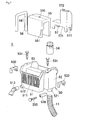
- Fig. 1 is a perspective view showing an aquarium system according to a first embodiment of the present invention.
- the aquarium system includes, as fundamental structural elements, an aquarium 1, an independent installation type filtering device 2 which is to be installed independently from the aquarium 1, an overflow device 5 for discharging water W from and introducing water W to the aquarium 1, an inlet hose 11, such as, e.g., an inlet pipe, for supplying water from the overflow device 5 to the filtering device 2, and an outlet hose 12, such as, e.g., an outlet pipe, for sending water from the filtering device 2 to the overflow device 5.
- an inlet hose 11 such as, e.g., an inlet pipe
- an outlet hose 12 such as, e.g., an outlet pipe
- the overflow device 5 is equipped with an overflow box 50 to be straddled on the side wall upper end of the aquarium 1.
- an overflow box 50 In the overflow box 50, a siphon pipe 55, a discharge pipe 56, and a sound insulating cover 57 are mounted.
- the overflow box 50 is constituted by an integrally formed resin molded article including a box-shaped tank-inside water storage portion 51 having an open upper end and configured to be disposed along a side wall inner surface of the aquarium 1, a box-shaped tank-outside water storage portion 52 having an open upper end and configured to be disposed along a sidewall outer surface of the aquarium 1, and a bridge connection portion 53 bridging upper end portions of both the water storage portions 51 and 52 and connecting both the water storage portions 51 and 52.
- One side wall portion of the tank-inside water storage portion 51 has a number of vertically extended slit-like water passage holes 511 arranged in parallel in the horizontal direction at certain intervals, so that the water W in the aquarium flows into the tank-inside water storage portion 51 via the water passage holes 511.
- the one side wall portion of the tank-inside water storage portion 51 is provided, at the lower end edge portion thereof, with a discharge opening 512 to which a discharge nozzle 513 is connected.
- the siphon pipe 55 is constituted by an inverted U-shaped or inverted ⁇ -shaped wide-width tubular member and configured so that the inlet side end portion is placed in the tank-inside water storage portion 51, the intermediate bent portion is placed on the bridge connection portion 53, and the outlet side end portion is placed in the tank-outside water storage portion 52.
- the siphon pipe 55 is filled with water W, if the water level at the side of the tank-inside water storage portion 51 is higher than the water level at the side of the tank-outside water storage portion 52, the water W in the tank-inside water storage portion 51 is fed to the side of the tank-outside water storage portion 52 via the siphon pipe 55 due to the difference in atmospheric pressure.
- a suction hole 555 is provided at the upper center of the intermediate bent portion (upper portion) of the siphon pipe 55. To this suction hole 555, a water suction intercept mechanism 8, which will be detailed, is connected.
- an inlet hose connection 521 is provided at one end portion of the lower wall of the tank-outside water storage portion 52.
- an overflow pipe 54 having a specified height is also provided on the lower wall upper surface of the water storage portion 52.
- the inlet side end portion of the inlet hose 11 made of a flexible hose is connected to the lower side of the inlet hose connection 521.
- the outlet side end portion of the inlet hose 11 is connected to the filtering device 2 as will be explained later so that the water W flowing out of the overflow device 5 is introduced into the filtering device 2 via the inlet hose 11.
- the tank-outside water storage portion 52 is provided with a sound insulating cover 57.
- This sound insulating cover 57 is formed into an above-water portion entirely covering type which covers the peripheral four sides and the upper surface of the region including the overflow pipe 54 above the water surface. Furthermore, the sound insulating cover 57 is provided with water flowing cutout portions 571 at the lower end of the peripheral side walls so that the water W stored in the tank-outside water storage portion 52 can flow into the sound insulating cover 57, i.e., the overflow pipe 54 side, via the water flowing cutout portions 571.
- Air release holes 572 and 572 are formed in the upper wall of the sound insulating cover 57 so that the inside of the sound insulating cover 57 can be maintained to the atmosphere pressure by allowing the air to flow in and out of the sound insulating cover 57 via the air release holes 572.
- an outlet hose connection 523 is provided.
- a discharge pipe 56 disposed in the overflow box 50 is formed into an inverted U-shape or -shape.
- the inlet side end portion of the discharge pipe 56 is fluidly communicated with the connection 523 of the tank-outside water storage portion 52.
- the middle bent portion is disposed along the bridge connection portion 53, and the outlet side end portion is fluidly communicated with the discharge nozzle 513 of the discharge opening 512 of the tank-inside water storage portion 51.
- a backflow preventing hole 561 is provided at the upper end portion of the tank-inside pipe portion of the discharge pipe 56 at the upper end portion of the tank-inside pipe portion of the discharge pipe 56. As will be explained later, this backflow preventing hole 561 prevents the water W in the aquarium from flowing back to the side of the filtering device 2 from the side of the discharge pipe 56 in the event that the discharge pump 35 suddenly stops due to, e.g., unexpected situations.
- an outlet side end portion of the outlet hose 12 is connected to the filtering device 2 as will be explained later.
- the water W discharged from the filtering device 2 is introduced into the overflow device 5 via the outlet hose connection 523 via the outlet hose 12, and the water is then discharged into the aquarium from the discharge nozzle 513 via the discharge pipe 56.
- a suction hole 565 is provided at the upper center of the intermediate bent portion (upper portion) of the discharge pipe 56. To the suction hole 565, the water suction intercept mechanism 8, which will be explained later, is connected.
- the water suction intercept mechanism 8 of this overflow device 5 is equipped with, e.g., a suction pump 80, a suction tube 81, a connection tube 82, a T-shaped pipe joint 86, a pipe joint member 87, etc.
- the T-shaped pipe joint 86 has three connecting portions communicated with each other.
- the first connecting portion of this pipe joint 86 is fluidly connected to the suction hole 555 of the siphon pipe 55.
- the second connecting portion of the pipe joint 86 is fluidly connected to one end of the suction tube 81.
- Also fluidly connected to the third connecting portion of the pipe joint 86 is one end of the connection tube.
- an electrically-operated suction pump 80 as suction means is connected so that the inside of the suction tube 81 is sucked by the suction operation of this pump 80.
- connection tube 82 is fluidly connected to the suction hole 565 of the discharge pipe 56 via the pipe joint member 87.
- a negative pressure is given to the inside of the suction tube 81 by the suction pump 80, which causes suction of the water or air (bubbles) in the siphon pipe 55 toward the pump 80 via the suction tube 81.
- the flowing of the water in the discharge pipe 56 causes a negative pressure in the connection tube 82, which causes suction of water and/or air (bubbles) in the siphon pipe 55 into the discharge pipe 56 via the connection tube 82.
- the overflow device 5 of this embodiment is configured such that, in cases where the driving of the suction pump 80 and/or the discharge pump 35, which will be explained later, is interrupted due to, e.g., power failure, air will be introduced into the siphon pipe 55 to immediately stop supply of water (suction of water) by the siphon pipe 55.
- the overflow device 5 is provided with height adjusting screws 531 and 531 on both sides of the bridge connection portion 53.
- the shaft tip end of each of the screws 531 and 531 is in contact with the upper end surface of the aquarium side wall via the contact frame 532.
- the overflow device 5 is provided with a perpendicular attitude control screw 535 on the lower surface of the tank-outside water storage portion 52 via the screw tube member 536.
- the head portion of the screw 535 is in contact with the outer surface of the aquarium side wall. Therefore, by adjusting the distance between the bottom portion of the tank-outside water storage portion 52 and the aquarium outer wall surface by changing the screwed amount of the screw 535, the horizontal attitude of the overflow device 5 can be adjusted.
- the filtering device 2 is equipped with a casing main body 21 having an opening at its upper end.
- the front portion constitutes a functional component zone Z1 and the rear side behind the functional component zone Z1 constitutes a filtration zone Z2.
- a functional component unit 3 is disposed in the functional component zone Z1 of the casing main body 21, and a filtration unit 4 is disposed in the filtration zone Z2.
- guide protrusions 25 continuously extending vertically between the functional component zone Z1 and the filtration zone Z2 are formed.
- the upper opening at the side of the functional component zone Z1 is covered with an upper wall member 34 of the functional component unit 3, and the upper opening at the side of the filtration zone Z2 is covered with a casing lid 22.
- the casing main body 21, the casing lid 22 and the upper wall member 34 of the functional component unit 3 constitute the casing 20.
- the functional component unit 3 includes a unit frame 31, a discharge pump 35, a protein skimmer 6, various connection members, and various pipes.
- the unit frame 31 is provided with a base plate 311 having a rectangular shape as seen from the top to be placed on the bottom surface of the casing main body 21, three vertical frames 312 upwardly extended from three corners of the base plate 311, and an inlet chamber 32 positioned at the upper side of the vertical frames 312.
- the inlet chamber 32 has an inlet chamber main body 33 supported by the upper ends of the vertical frames 312 and an upper wall member 34 detachably attached to the upper end opening portion of the inlet chamber main body 33.
- the inlet chamber main body 33 is disposed so that the upper end open portion thereof corresponds to the upper end opening portion at the side of the functional component zone Z1 of the casing main body 21. Therefore, the upper wall member 34 closing the upper end opening portion of the inlet chamber main body 33 also functions as a lid member (a part of the upper wall) of the casing main body 21.
- the upper wall member 34 has an inlet hose connection 341, an outlet hose connection 342, a protein skimmer connection 343 and a stone replacement operation portion 344.
- the outlet side end portion of the inlet hose 11 connected to the overflow device 5 is fluidly connected. While, to the outlet hose connection 342, the inlet side end portion of the outlet hose 11 connected to the overflow device 5 is fluidly connected.
- the inlet hose connection 341 has, at the lower surface side of the upper wall member 34, a flow dividing plate 346. As shown in Fig. 12 , this flow dividing plate 346 has chamber communication holes 347 communicated with the inlet chamber 32, and is connected to the inlet side end portion of the protein skimmer connection pipe 67. Thus, among the water W introduced through the inlet hose 11, a part of the water W is introduced into the protein skimmer 6 via the protein skimmer connection pipe 67, while the rest of the water W is introduced into the inlet chamber 32 via the chamber communication holes 347.
- a filtration zone communication opening 331 communicated with the filtration zone Z2 is formed in the rear wall of the inlet chamber main body 33.
- the water W introduced into the inlet chamber 32 via the inlet hose connection 341 is introduced into the filtration zone Z2 through the filtration zone communication opening 331.
- the discharge pump 35 is fixed to the upper surface of the base plate 311 of the unit frame 31.
- the outlet port of the discharge pump 35 is in fluid communication with the lower end of the discharge pipe 351.
- the upper end of this discharge pipe 351 is penetrated through the inlet chamber 32 and is in fluid communication with the discharge hose connection 342 of the upper wall member 34.
- it is configured such that the water W stored in the bottom portion of the casing main body 21 is fed to the discharge pipe 351 by the discharge pump 35 and then the water W passes through the outlet hose 12 to be supplied to the overflow device 5.
- the protein skimmer 6 has a vertically disposed skimmer main pipe 61 with the lower end fixed to the base plate 311 of the unit frame 31.
- the upper end of the skimmer main pipe 61 penetrates the inlet chamber 32 to be disposed above the upper part of the upper wall member 34.
- a tapered pipe 62 with a radius gradually decreasing towards the upper portion thereof is provided.
- a protein skimmer cup 63 covering the upper tapered portion of the tapered pipe 62.
- This protein skimmer cup 63 is provided with a discharge spout 631 for discharging organic series contaminants, such as, e.g., protein, accumulated in the cup as will be described later.
- the protein skimmer connection pipe 67 penetrates in the upper portion of the skimmer main pipe 61, so that a part of the water W divided by the flow dividing plate 346 in the chamber upper wall member 34 is introduced into the skimmer main pipe 61 of the protein skimmer 6 via the connection pipe 67.
- the lower end of the inclined pipe 64 is fluidly connected to the lower end portion of the skimmer main pipe 61.
- the inclined pipe 64 is placed so that it extends obliquely upward from the lower end portion of the skimmer main pipe 61.
- the upper end of the inclined pipe 64 penetrates the inlet chamber 32 to be connected to the stone replacement operation portion 344 of the upper wall member 34.
- the inclined pipe 64 is provided with blocking members 651 and 652 fitted and attached to the upper end and the lower end of the inclined pipe 64. Also, in the inclined pipe 64, a hard air supplying pipe 65 is disposed in a state in which the pipe penetrates both the blocking members 651 and 652. The tip end of the air supplying pipe 65 is placed at the lower end portion of the skimmer main pipe 61.
- a wood stone 66 as a bubble generating means is placed at the lower end portion of the skimmer main pipe 61, and the wood stone 66 is communicated with the tip end of the air supplying pipe 65.
- the wood stone 66 is formed into an elongated cylindrical shape with a diameter smaller than the inner diameter of the inclined pipe 64 so that it can be inserted in the inclined pipe 64. Therefore, by pulling out the air supplying pipe 65 from the inclined pipe 64, the wood stone 66 can be taken out from the skimmer main pipe 61 together with the air supplying pipe 65 via the inclined pipe 64.
- the wood stone 66 can be placed at a predetermined position in the lower portion of the skimmer main pipe 61.
- the wood stone 66 can be taken in and out without troublesome operations, such as, disassembling operations of the other components.
- the wood stone 66 has a number of fine pores, and can generate a number of bubbles by supplying air to the wood stone 66 via the air supplying pipe 65 in a state in which the wood stone 66 is immersed in the stored water W in the skimmer main pipe 61.
- Organic series contaminants, such as, e.g., protein, contained in the water adhere to the generated bubbles, and they move upwards.
- the upwardly moved proteins further go up through the skimmer main pipe 61 to be discharged from the upper end of the tapered pipe 62, collected within the protein skimmer cup 63, and then discharged to the outside via the discharge spout 631.
- the lower end of the overflow pipe 68 is connected. While, the upper end of the overflow pipe 68 is disposed at the lower portion of the inlet chamber 38 of the filtration zone Z1.
- the water W supplied to the skimmer main pipe 61 is stored more than the specified amount, the water W is discharged to the inside of the casing 20 but outside the protein skimmer 6 via the overflow pipe 68.
- the inlet chamber 32 and the base plate 311 are each formed to have a plane shape corresponding to the plane cross-section of the functional component zone Z1 of the casing main body 21.
- the unit 3 can be inserted into and removed from the functional component zone Z1 of the casing main body 21 via the upper end opening thereof.
- the rear ends of both side portions of the inlet chamber 32 and those of the base plate 311 of the unit 3 are engaged with and guided by the guide protrusions 25 formed on the inner side surfaces of the casing main body 21, so that the insertion/removal operation of the unit 3 can be performed smoothly.
- the functional component unit 3 can be inserted and removed from the casing main body 21.
- the filtration unit 4 includes a lower bucket 41, a middle bucket 42, a water spray tray 43, a drain board 44 and a gutter member 45.
- Each of the buckets 41 and 42 is formed into an upper opened box shape and is provided with a number of water spraying holes 411 and 421 formed in the bottom wall, so that the water W supplied to the inside of the buckets 41 and 42 are poured out downward through the water spraying holes 411 and 421.
- the middle bucket 42 is accommodated in the filtration zone Z2 of the casing main body 21 with the middle bucket placed on the lower bucket 41.
- the water spray tray 43 is formed into an upper opened shallow box shape and has a number of water spraying holes 431 formed in the bottom wall thereof. Also, the water spray tray 43 is provided with spacer protrusions 432 formed on the bottom surface thereof.
- the water spray tray 43 is accommodated in the filtration zone Z2 of the casing main body 21 with the water spray tray placed on the middle bucket 42.
- the drain board 44 is formed into a shape corresponding to the inner circumferential shape of the water spray tray 43, and has a number of water spraying holes 441.
- This drain board 44 is placed on the spacer protrusions 432 of the water spray tray 43.
- the drain board 44 is accommodated in the water spray tray 43 in a fitted manner with a substantial space formed between the drain board and the bottom of the water spray tray 43.
- the gutter member 45 is formed into an upper opened channel shape and has a number of water spraying holes 451 formed in the bottom wall.
- the front end (the functional component zone side end portion) of the gutter member 45 is opened, while the rear end is closed.
- the gutter member 45 is disposed on the water spray tray 43 via the drain board 44 with the front opened end portion facing the filtration zone communication opening 331 of the inlet chamber 32 of the functional component unit 3.
- the gutter member 45 is provided with a water guiding tongue portion 452 forwardly extended from the bottom wall front end thereof.
- This tongue portion 452 is inserted into the filtration zone communication opening 331 and engaged with the inlet chamber 32 of the functional component unit 3. Consequently, the stored water W in the inlet chamber 32 is guided by the tongue portion 452 and supplied smoothly to the gutter member 45 via the communication opening 331.
- each of the constituent components 41 to 45 can be inserted into and detached from the upper end opening of the filtration zone Z2 of the casing main body 21.
- the buckets 41 and 42 and the water spray tray 43 are each formed into a shape corresponding to the plan cross-sectional shape of the filtration zone Z2. Therefore, when these members 41 to 43 are insert into or detached from the filtration zone Z2 of the casing main body 21, front both side portions of the buckets 41 and 42 and those of the water spray tray 43 are engaged with and guided by the guiding protrusions 25 formed on the inner side surfaces of the casing 21, so that insertion/removal operation of each of the members 41 to 45 can be performed with high dimensional accuracy.
- each of the components 41 to 45 of the filtration unit 4 can be inserted into and detached from the casing main body 21.
- the aforementioned casing lid 22 is detachably attached via a packing (not shown).
- the casing 20 is constituted by attaching the casing lit 22 and the upper wall member 34 of the functional component unit 3 to the casing main body 21.
- the interior of the casing 20 is open to the atmosphere.
- the casing lid 22 has an atmospheric communication opening 221, so that air is allowed to go into and out of the casing 20 via the communication opening 221.
- the interior of the casing 20 is open to the atmosphere.
- the reference numeral “352" denotes a power cord of the discharge pump 35
- the reference numeral “655" denotes an air supplying means for supplying air to the wood stone 66 via the air supplying pipe 65.
- filtration materials 71 to 73 are initially set to the filtering device 2.
- a filtration material 71 such as, e.g., Siporax, in which anaerobic filtering bacteria can be grown, is accommodated to perform biofiltration.
- a filtration material 72 such as, e.g., bio ball, in which aerobic filtration bacteria can be grown, is accommodated to perform biofiltration.
- a filtration material 73 such as, e.g., wool or activated carbon, is accommodated via the drain board 44 to perform physical filtration.
- the overflow device 5 is set so as to straddle the side wall upper end of the aquarium 1.
- the tank-inside water storage portion 51 of the overflow device 5 is immersed in the water W in the aquarium to a predetermined level, so that the water W in the aquarium flows into the storage portion 51 via the water passage holes 511.
- a specified amount of water is stored in the tank-inside water storage portion 51.
- a physical filtration material (not shown), such as, e.g., sponge.
- hoses 11 and 12 are set between the filtering device 2 and the overflow device 5.
- the inlet side end portion of the inlet hose 11 is fluidly connected to the inlet hose connection 521 of the overflow device 5, while the outlet side end portion thereof is fluidly connected to the inlet hose connection 341 of the filtering device 2.
- the inlet side end portion of the outlet hose 12 is fluidly connected to the outlet hose connection 342 of the filtering device 2, while the outlet side end portion thereof is fluidly connected to the outlet hose connection 523 of the overflow device 5.
- the sound insulating cover 57 is set in the tank-outside water storage portion 52 so as to cover the entire periphery of the overflow pipe 54.
- water W is filled to a level slightly lower than the water level of the tank-inside water storage portion 51.
- the operation of the aquarium system is initiated. That is, the discharge pump 35 of the filtering device 2 and the suction pump 80 of the overflow device 5 are activated, and air is supplied to the wood stone 66 of the protein skimmer 6.
- water W is fed to the discharge pipe 351 by the discharge pump 35, and the water W is fed to the discharge pipe 56 of the overflow device 5 through the outlet hose 12.
- the water W fed to the discharge pipe 56 is discharged to the aquarium 1 from the discharge nozzle 513.
- the water W in the filtering device 2 is fed to the aquarium 1.
- the air in the siphon pipe 55 is sucked from the suction hole 555 of the siphon pipe 55 via the suction tube 81, so that the siphon pipe 55 is filled with water W.
- the water level difference between the aquarium 1 and the tank-outside water storage portion 52 of the overflow device 5 causes a suction function (siphon phenomenon) of the siphon pipe 55, which in turn causes the water W in the aquarium to be supplied from the tank-inside water storage portion 51 to the tank-outside water storage 52 via the siphon pipe 55.
- the water W flows into the overflow pipe 54 and is supplied to the casing 20 of the filtering device 2 through the inlet hose 11.
- the water W fed to the casing 20 is divided by the flow dividing plate 346 at the inlet hose connection 341, and most of the water W is introduced into the inlet chamber 32 through the chamber communication holes 347, and the remaining water W is introduced into the skimmer main pipe 61 of the protein skimmer 6 through the protein skimmer connection pipe 67.
- Protein contained in the water W introduced into the protein skimmer 6 is removed. That is, a wood stone 66 is disposed in the water introduced into and stored in the skimmer main pipe 61, and a number of bubbles are generated from the wood stone 66. The protein in the water adheres to these bubbles, floats, sequentially moves upwards, and gradually goes upward through the skimmer main pipe 61. These ascended bubbles with protein are discharged from the upper end of the tapered pipe 62, collected in the protein skimmer cup 63 and discharged to the outside from the discharge spout 631. Thus, only protein is discharged and removed from the water.
- the water W from which protein is removed goes through the overflow pipe 68 of the protein skimmer 6 and discharged into the casing which is outside the protein skimmer 6.
- the water W introduced into the inlet chamber 32 is supplied to the gutter member 45 in the filtration zone Z2 through the filtration zone communication opening 331.
- the water supplied to the gutter member 45 is dispersed and drops through a number of water spraying holes 451, and is supplied to nearly the entire area of the filtration material 73 of the water spray tray 43 in a dispersed manner.
- the water W supplied to the filtration material 73 passes through the drain board 44, and is dispersed and drops through a number of water spraying holes 431 of the water spray tray 43 and then supplied to nearly the entire area of the filtration material 72 of the middle bucket 42.
- the water W supplied to the filtration material 72, such as, e.g., a bio ball, in the middle bucket 42 is biologically filtered by the aerobic filter bacteria adhered to the filtration material 72, and then dispersed and drops through a number of water spraying holes 421 to be supplied to nearly the entire area of the filtration material 71 of the lower bucket 41.
- the water W supplied to the filtration material 71, such as, e.g., Siporax, in the lower bucket 41 is biologically filtered by the anaerobic filter bacteria adhered to the filtration material 71, and supplied to the bottom portion of the casing 20 through a number of water spraying holes 511.
- the water W filtered as mentioned above flows from the filtration zone Z2 to the functional component zone Z1, and is fed to the discharge pipe 351 by the discharge pump 35 and then supplied to the aquarium 1 in the same manner as mentioned above.
- the backflow preventing hole 561 formed in the upper end portion of the tank-inside pipe portion of the discharge pipe 56 causes introduction of air into the discharge pipe 56 via the backflow preventing hole 561 when the water W in the discharge pipe 56 starts backward flow. This prevents suction of the water W in the aquarium into the discharge pipe 56, which in turn prevents the water in the aquarium from flowing back to the filtering device 2.
- the siphon pipe 55 and the discharge pipe 56 are connected via the connection tube 82, the water supply by the siphon pipe 55 can be interrupted.
- the air will be introduced into the discharge pipe 56 as explained above, which causes air to be introduced into the siphon pipe 55 via the backflow preventing hole 561, the discharge pipe 56 and the connection tube 82.
- the air introduced into the siphon pipe 55 will not be sucked and/or discharged via the suction tube 81, causing a sufficient amount of air to be introduced into the upper portion of the siphon pipe 55.
- This air causes the water in the siphon pipe 55 to be divided into the water at the inlet side pipe portion of the siphon pipe 55 and the water at the outlet side pipe portion of the siphon pipe 55. This prevents the water W in the aquarium from being sucked into the siphon pipe 55, resulting in immediate interception of the water supply by the siphon pipe 55.
- the discharge pump 35 when the discharge pump 35 is driven, the water in the filtering device 2 will be forcibly discharged into the aquarium via the outlet hose 12 and the discharge pipe 56.
- a negative pressure will be given to the connection tube 82 from the side of the discharge pipe 56.
- the suction function the air in the siphon pipe 55 is sucked and discharged via the connection tube 82, and at the same time, the driving of the suction pump 80 is resumed, which causes the air in the siphon pipe 55 to be sucked and discharged via the suction tube 81.
- the air in the siphon pipe 55 is discharged, causing the water W in the aquarium to be sucked by the siphon pipe 55 and supplied to the filtering device 2.
- the casing 20 is clearly divided into the functional component zone Z1 and the filtration zone Z2 and the functional component unit 3 is detachably accommodated in the functional component zone Z1. Therefore, the functional component unit 3 can be easily detached, so that the maintenance and repair of the pump 35 and/or the protein skimmer 6 constituting the unit 3 can be easily performed. Furthermore, the functional component unit 3 includes the pump power cord and various pipes as well as the inlet hose connection 341, the outlet hose connection 342, the protein skimmer connection 343, and the stone replacement operation portion 344, so these components and members could also be easily maintained.
- the discharge pump 35 can be easily deteriorated or damaged as compared to other components.
- the pump 35 can be easily maintained, the usability of the filtering device 2 can be dramatically improved.
- the wood stone 66 of the protein skimmer 6 can be easily replaced. That is, the upper end portion of the inclined pipe 64 connected to the lower end portion of the skimmer main pipe 61 is opened at the upper surface of the upper wall member 34 of the functional component unit 3, and the wood stone 66 with the air supply pipe 65 is inserted from the upper end opening portion of the inclined pipe 64 and placed at the specified position of the skimmer main pipe 61. Therefore, by pulling out the air supplying pipe 64 from the upper end opening portion of the inclined pipe 64, the wood stone 66 can be detached together with the air supplying pipe 65.
- the wood stone 66 can be easily detached and replaced with new one without removing the skimmer main pipe 61 and/or disassembling the other components. Especially, in the case of the wood stone 66, although the exchanging timing is short due to clogging, the replacement of the wood stone 66 can be made easily. This further improves the usability of the filtering device 2.
- the casing 20 is provided with the inlet chamber 32 so that the water W from the aquarium 1 can be once stored in the inlet chamber 32 and then supplied from this chamber 32 to the filtration zone Z2. This enables stable supply of water W to the filtration zone Z2, which in turn can improve the filtration capability.
- the inside of the casing 20 is open to the atmosphere and the upper portion of the casing 20 is in contact with air.
- filtering by aerobic filtering bacteria can be performed, which further improves the filtering capability.
- the filtering device 2 of this first embodiment as the filtration materials 71 to 73, filtering of different types is sequentially performed using wool or activated carbon for physical filtering, the bio ball for aerobic bacterial filtering, and Siporax for anaerobic bacterial filtering.
- the water W of the aquarium can be filtered assuredly and kept clean by the dry and wet method, which can keep the aquarium in the optimal environment for aquarium fish and the like.
- different types of filtration materials 71 to 73 are stacked to form the filtration zone Z2 to cause the water W to pass through each of the filtration materials 71 to 73 sequentially from the upper one. Therefore, it is possible to assuredly pass the water W through each of the filtration materials 71 to 73 by gravity fall to thereby improve the filtering capability more assuredly.
- the overflow device 5 of the aquarium system of this first embodiment it is possible to avoid harmful effects to the peripheral environment caused by the suction sound occurring when the water W is sucked from the overflow pipe 54.
- a normal overflow pipe 54 water and air are irregularly suctioned when the water W is suctioned from the upper end of the overflow pipe, generating the suction sound of air.
- the sound insulating cover 57 is mounted in the tank-outside water storage portion 52 so that the sound insulating cover 57 covers all of the four peripheral side surfaces and the upper surface of the above-water area of the periphery of the overflow pipe 54.
- the suction sound is intercepted by the sound insulating cover 57 and trapped in the cover 57. In this way, the suction sound is intercepted and prevented from spreading outside, so there are no harmful effects of the suction sound to the peripheral environment, and troubles caused by the suction sound can be assuredly prevented.
- Figs. 14 to 16 show a water suction interception mechanism 8 of an overflow device 5 in an aquarium system according to a second embodiment of this invention.
- the siphon pipe 55 and the discharge pipe 56 of this overflow device 5 are provided with suction holes 555 and 556 in the same manner as in the aforementioned embodiment.
- One end of the connection tube 82 is fluidly connected to the siphon side suction hole 555 via the pipe joint 87, and the other end thereof is fluidly connected to the discharge side suction hole 565 via the pipe joint 87.
- the suction pump 80 and suction tube 81 are not provided.
- connection tube 82 and the discharge pipe 56 constitute suction means, and the connection tube constitutes air introduction means.
- the other structure is essentially the same as that of the first embodiment, and therefore the cumulative explanation will be omitted by allotting the same reference numeral to the same or corresponding portion.
- the water in the filtering device 2 will be forcibly discharged into the aquarium via the outlet hole 12 and discharge pipe 56.
- a negative pressure will be given to the connection tube 82 from the side of the discharge pipe 56. Accordingly, by this suction function, the air in the siphon pipe 55 will be sucked and discharged via the connection tube 82.
- the air in the siphon pipe 55 is discharged, causing the water W in the aquarium to be sucked by the siphon pipe 55 and supplied to the filtering device 2.
- overflow device 5 of this second embodiment without requiring a suction pump, in the same manner as in the first embodiment, unexpected sucking of water by the siphon pipe 55 and the discharge pipe 56 can be intercepted, and the system can be automatically recovered after power recovery.
- the elimination of a suction pump decreases the number of components, resulting in simplified structure and reduced cost.
- Figs. 17 to 19 show a water suction interception mechanism 8 of an overflow device 5 in an aquarium system according to a third embodiment of this invention.
- the siphon pipe 55 of this overflow device 5 is provided with a suction hole 555 in the same manner as mentioned above.
- a first connecting portion of the T-shaped pipe joint 86 is fluidly connected.
- a second connecting portion of the pipe join 86 is one end of the suction tube 81 with the other end thereof connected to a suction pump 80.
- This control valve 85 is comprised of an electromagnetic valve which is configured to maintain its closed state when the power is turned on and turn to an open state when the power is turned off.
- no suction hole is formed in the discharge pipe 56.
- the suction pipe 56 and the siphon pipe 55 are not communicated via the suction hole.
- the suction pump 80 and the suction tube 81 constitute a suction means
- the air introduction tube 83 and the control valve 85 constitute an air introduction means.
- the other structure is essentially the same as that of the aforementioned embodiments, and therefore the cumulative explanation will be omitted by allotting the same reference numeral to the same or corresponding portion.
- the suction by the suction pipe 80 to the siphon pipe 55 is stopped and the control valve 85 is opened, causing outside air (air) to be introduced into the siphon pipe 55 via the control valve 85 and the air introduction tube 83.
- the introduced air causes the water W in the siphon pipe 55 to be separated into the water W in the inlet side pipe portion of the siphon pipe 55 and the water W in the outlet side pipe portion thereof. This prevents the water W in the aquarium to be sucked into the siphon pipe 55, resulting in immediate interception of the water supply by the siphon pipe 55.
- the discharge pump 35 suddenly stops due to, e.g., power failure, the backward flow of the water W in the aquarium to the outlet hose 12 can be prevented, and at the same time, the supply of the water W by the siphon pipe 55 can be automatically interrupted without delay.
- the discharge pump 35 when the discharge pump 35 is driven, the water in the filtering device 2 will be forcibly discharged into the aquarium via the outlet hole 12 and discharge pipe 56.
- the suction pump 80 by driving the suction pump 80, the air in the siphon pipe 55 will be sucked and discharged via the suction tube 81.
- the air in the siphon pipe 55 is discharged, causing the water W in the aquarium to be sucked by the siphon pipe 55 and supplied to the filtering device 2.
- the functional component unit 3 of the aquarium filtering device 2 includes the discharge pump 35 and the protein skimmer 6, the present invention is not limited to it. In the present invention, it is not required that the functional component unit 3 includes the protein skimmer. Furthermore, the functional component unit 3 can include a heater, an air blower, a cooler or the like, for adjusting the water temperature.
- the tank-inside water storage portion 51 is provided in the aquarium 1 so that the water W in the aquarium is supplied to the tank-outside water storage portion 52 via the siphon pipe 55, but the present invention is not limited to that. In the present invention, it is not always required to provide the tank-inside water storage portion.
- the inlet side end portion of the siphon pipe can be placed directly in the aquarium.
- the present invention is not limited to it.
- the present invention can also be applied to an overflow device in which water W discharged from a filtration device is once stored in a water storage portion provided in the aquarium and then the water W is supplied from the water storage portion to the aquarium via an overflow pipe.
- the aquarium overflow device according to the present invention can be used for an aquarium equipment for supplying water in an aquarium for aquarium fish, etc., to a filtering device, etc.
Landscapes
- Life Sciences & Earth Sciences (AREA)
- Environmental Sciences (AREA)
- Marine Sciences & Fisheries (AREA)
- Animal Husbandry (AREA)
- Biodiversity & Conservation Biology (AREA)
- Farming Of Fish And Shellfish (AREA)
- Devices That Are Associated With Refrigeration Equipment (AREA)
- Treatment Of Biological Wastes In General (AREA)
Applications Claiming Priority (2)
| Application Number | Priority Date | Filing Date | Title |
|---|---|---|---|
| JP2006228892 | 2006-08-25 | ||
| PCT/JP2007/064151 WO2008023512A1 (en) | 2006-08-25 | 2007-07-18 | Overflow device for water tank |
Publications (3)
| Publication Number | Publication Date |
|---|---|
| EP2055185A1 true EP2055185A1 (de) | 2009-05-06 |
| EP2055185A4 EP2055185A4 (de) | 2012-06-13 |
| EP2055185B1 EP2055185B1 (de) | 2016-09-07 |
Family
ID=39106604
Family Applications (2)
| Application Number | Title | Priority Date | Filing Date |
|---|---|---|---|
| EP07790906.7A Not-in-force EP2055185B1 (de) | 2006-08-25 | 2007-07-18 | Überlaufvorrichtung für wassertank |
| EP20070790908 Not-in-force EP2055186B1 (de) | 2006-08-25 | 2007-07-18 | Überlaufvorrichtung für wassertank |
Family Applications After (1)
| Application Number | Title | Priority Date | Filing Date |
|---|---|---|---|
| EP20070790908 Not-in-force EP2055186B1 (de) | 2006-08-25 | 2007-07-18 | Überlaufvorrichtung für wassertank |
Country Status (6)
| Country | Link |
|---|---|
| US (2) | US8132534B2 (de) |
| EP (2) | EP2055185B1 (de) |
| JP (2) | JP4950202B2 (de) |
| CN (2) | CN101588713B (de) |
| AT (1) | ATE530065T1 (de) |
| WO (2) | WO2008023513A1 (de) |
Families Citing this family (24)
| Publication number | Priority date | Publication date | Assignee | Title |
|---|---|---|---|---|
| US8132534B2 (en) * | 2006-08-25 | 2012-03-13 | Kabushiki Kaisha Tominaga Jyushi Kogyosho | Overflow device for water tank |
| US8443828B2 (en) | 2010-07-15 | 2013-05-21 | Zenon Technology Partnership | Siphon weir valve for high flow municipal water treatment systems |
| JP5818732B2 (ja) * | 2012-03-29 | 2015-11-18 | 旭化成ケミカルズ株式会社 | 電解セル及び電解槽 |
| US9167804B2 (en) * | 2012-05-31 | 2015-10-27 | John Musser | Recirculating fish brooding and filtration system |
| US9788533B2 (en) * | 2012-10-09 | 2017-10-17 | Elive Llc | Aquarium filter |
| US9585372B2 (en) | 2015-02-06 | 2017-03-07 | Adam John Keller | Water inlet system for an aquarium, a siphon stopper and a method of attaching the system to an aquarium |
| US9409804B1 (en) | 2015-02-06 | 2016-08-09 | Adam John Keller | Filter system for a fluid |
| US9737058B2 (en) | 2015-02-06 | 2017-08-22 | Adam John Keller | Overflow system for a tank and a method of affixing the overflow system to the tank |
| US9908268B2 (en) | 2015-02-06 | 2018-03-06 | Adam John Keller | Baffle tank for filtering a fluid and a method of forming the baffle tank |
| US10130087B1 (en) * | 2015-10-30 | 2018-11-20 | Victor Manuel Alas, Jr. | Chum dispenser |
| US10599664B2 (en) * | 2016-04-22 | 2020-03-24 | Cloudera, Inc. | Interactive identification of similar SQL queries |
| CN106172168B (zh) * | 2016-07-25 | 2019-07-26 | 丁丽军 | 一种养鱼场给水排污装置及其使用方法 |
| CN106465662B (zh) * | 2016-09-09 | 2019-05-21 | 东北农业大学 | 一种人工气候箱内置水稻育秧专用供水系统 |
| US10070630B2 (en) * | 2016-12-28 | 2018-09-11 | Adam John Keller | Overflow box and filter system for an aquarium |
| CN106889014B (zh) * | 2017-04-26 | 2023-10-27 | 崔勋 | 负压虹吸系统 |
| USD830496S1 (en) | 2017-09-06 | 2018-10-09 | Dennis R. Washburn | Overflow sensor tank |
| KR102142373B1 (ko) * | 2019-11-20 | 2020-08-07 | 주식회사 덕신양행 | 유체펌프 |
| CN110959572B (zh) * | 2019-12-16 | 2023-08-11 | 广州誉隆智慧科技有限公司 | 一种增氧装置 |
| US11412717B1 (en) | 2020-05-05 | 2022-08-16 | Central Garden & Pet Company | Movable spout for an aquarium |
| US11641848B1 (en) | 2020-05-05 | 2023-05-09 | Central Garden & Pet Company | Variable flow spout for an aquarium |
| US12144326B1 (en) | 2020-05-05 | 2024-11-19 | Central Garden & Pet Company | Pumping arrangement for an aquarium |
| CN112005951A (zh) * | 2020-08-13 | 2020-12-01 | 按钮科技(杭州)有限公司 | 一种具有可产生无死角暗流组件的鱼缸 |
| KR102665075B1 (ko) * | 2021-01-13 | 2024-05-09 | 김진영 | 에너지 저장장치 |
| GB2612351A (en) * | 2021-10-29 | 2023-05-03 | Vortech Water Solutions Ltd | Siphon assembly |
Family Cites Families (46)
| Publication number | Priority date | Publication date | Assignee | Title |
|---|---|---|---|---|
| US853705A (en) * | 1905-08-28 | 1907-05-14 | Columbus Brass Company | Flush-tank. |
| US832764A (en) * | 1905-12-20 | 1906-10-09 | James Nelson Wood | Siphon water-elevator. |
| US1607801A (en) * | 1920-12-20 | 1926-11-23 | Allis Chalmers Mfg Co | Oil-circulating system |
| US2131743A (en) * | 1934-12-03 | 1938-10-04 | Matthew H Loughridge | Venturi siphon |
| US2363539A (en) * | 1941-03-20 | 1944-11-28 | William R Lockridge | Siphon system |
| US3261471A (en) * | 1962-05-23 | 1966-07-19 | Halvin Products Company Inc | Aquarium filter system |
| US3304564A (en) * | 1965-10-04 | 1967-02-21 | Green Jack | Apparatus for cleaning a body of liquid and maintaining its level |
| US3485373A (en) * | 1966-12-21 | 1969-12-23 | Edgar A Powers | Means for power siphoning of liquid from one tank to another,especially for aquariums |
| US3552568A (en) * | 1967-11-22 | 1971-01-05 | Purex Corp Ltd | Pool chlorination |
| US3513978A (en) * | 1968-05-27 | 1970-05-26 | Robert Newsteder | External water treating device for aquaria |
| US3675672A (en) * | 1969-07-17 | 1972-07-11 | Bowles Fluidics Corp | Fluidic irrigation |
| US3669297A (en) * | 1970-06-03 | 1972-06-13 | Metaframe Corp | Automatic siphoning filtration device |
| US4035299A (en) * | 1975-05-13 | 1977-07-12 | Crine Vroeginday | Method of initiating a fluid flow within a siphon tube between an aquarium and its associated filter tank |
| US4036756A (en) * | 1975-06-10 | 1977-07-19 | Dockery Denzel J | Aquarium filter assembly |
| US4220530A (en) * | 1979-05-29 | 1980-09-02 | Gabriele Raymond S | Fish tank filter |
| JPS58180467A (ja) | 1982-04-16 | 1983-10-21 | Sumitomo Chem Co Ltd | ビスフエノ−ル誘導体およびその製造法 |
| US4610784A (en) * | 1984-12-21 | 1986-09-09 | Lance Reyniers | Method and apparatus for cleaning and filling an aquarium |
| JPS6224100A (ja) * | 1985-07-25 | 1987-02-02 | Maezawa Kogyo Kk | 通水管路の緊急遮断方法及びその装置 |
| JPS62113900A (ja) * | 1985-11-12 | 1987-05-25 | Ebara Corp | ポンプ吸水槽 |
| US4684462A (en) * | 1986-06-16 | 1987-08-04 | Augustyniak George E | Filtration, aeration, and water level control means for aquariums |
| JP2965295B2 (ja) * | 1986-10-01 | 1999-10-18 | 堯之 久原 | 複数の水槽を備えた蓄熱槽の運転制御方法 |
| US4861465A (en) * | 1988-01-25 | 1989-08-29 | Augustyniak Stanley D | Anti-reverse siphoning water circulating system for aquariums |
| JPH0318619A (ja) | 1989-06-14 | 1991-01-28 | Nissan Motor Co Ltd | 渦流室式ディーゼル機関の燃焼室 |
| JPH087774Y2 (ja) * | 1989-06-30 | 1996-03-04 | 株式会社イトーキクレビオ | 二重床におけるコンセント装置 |
| JPH0634665B2 (ja) | 1989-08-11 | 1994-05-11 | 光正 佐藤 | 定水位給排水装置及びこれを用いた開放型定水位水循環装置 |
| JP2922539B2 (ja) | 1989-09-30 | 1999-07-26 | アイシン精機株式会社 | 医療用ポンプシステム |
| US5114936A (en) | 1990-08-23 | 1992-05-19 | Hoechst-Roussel Pharmaceuticals Incorporated | 6,7-dihydro-3-phenyl-1,2-benzisoxazol-4(5h)-ones and -ols, compositions and pharmaceutical use |
| JPH05231397A (ja) * | 1992-02-26 | 1993-09-07 | Kubota Corp | ポンプ |
| JP3118073B2 (ja) | 1992-03-16 | 2000-12-18 | 日本信号株式会社 | 列車制御用通信装置 |
| JP3072829B2 (ja) | 1994-12-27 | 2000-08-07 | キヤノン株式会社 | カラー液晶パネル |
| US5628905A (en) * | 1995-04-04 | 1997-05-13 | Montalbano; Gregory | Biological aquarium filter with means to keep the siphon tubes primed |
| JP3018619U (ja) * | 1995-05-24 | 1995-11-28 | 株式会社広瀬 | 改良型水落下システム付水槽及び濾過装置 |
| JPH10122200A (ja) * | 1996-10-23 | 1998-05-12 | Mitsubishi Heavy Ind Ltd | サイフォン管の逆流防止装置 |
| JPH1193223A (ja) * | 1997-09-17 | 1999-04-06 | Emuzu Tecnica:Kk | 給排水管可動の定水位給排水装置及びこれを用いた生魚自動販売装置 |
| JPH11132200A (ja) * | 1997-10-28 | 1999-05-18 | Tesuko:Kk | 複数段水槽の定水位給排水装置、及びこれを用いた複数段水槽の循環ビオトープ水系装置 |
| US6056886A (en) * | 1998-06-08 | 2000-05-02 | Aquaria, Inc. | Water level and flow control device and skimmer box provided with this device |
| JP2000179465A (ja) * | 1998-10-05 | 2000-06-27 | Tominaga Jushi Kogyosho:Kk | 観賞魚水槽用空気・水兼用ポンプおよび回遊路付観賞魚水槽装置 |
| US6299765B1 (en) * | 1999-05-19 | 2001-10-09 | Robert A. Fabrizio | Surface feed filter pump box for aquariums |
| JP2001252506A (ja) * | 2000-03-14 | 2001-09-18 | Tokyo Metropolis | 自然平衡濾過池の濾過部材の逆洗方法及び自然平衡濾過池における濾過方法 |
| CN2424621Y (zh) * | 2000-06-25 | 2001-03-28 | 胡立文 | 水平衡调节装置 |
| JP3605582B2 (ja) * | 2001-08-07 | 2004-12-22 | 水作株式会社 | 外部式濾過装置 |
| US7001509B1 (en) * | 2004-09-09 | 2006-02-21 | Chi-Hung Lin | Aquarium filter having self-priming arrangement |
| JP2006228892A (ja) | 2005-02-16 | 2006-08-31 | Matsushita Electric Ind Co Ltd | 半導体発光素子及びその製造方法 |
| JP3118073U (ja) * | 2005-10-28 | 2006-01-19 | ▲めい▼光股▲ふん▼有限公司 | 鑑賞魚用水槽用濾過装置の逆流防止構造 |
| EP1997371A4 (de) * | 2006-03-22 | 2010-03-03 | Tominaga Jyushi Kogyosho Kk | Überlaufvorrichtung für wassertank |
| US8132534B2 (en) * | 2006-08-25 | 2012-03-13 | Kabushiki Kaisha Tominaga Jyushi Kogyosho | Overflow device for water tank |
-
2007
- 2007-07-18 US US12/310,419 patent/US8132534B2/en not_active Expired - Fee Related
- 2007-07-18 AT AT07790908T patent/ATE530065T1/de not_active IP Right Cessation
- 2007-07-18 US US12/310,426 patent/US20100012559A1/en not_active Abandoned
- 2007-07-18 JP JP2008530831A patent/JP4950202B2/ja not_active Expired - Fee Related
- 2007-07-18 EP EP07790906.7A patent/EP2055185B1/de not_active Not-in-force
- 2007-07-18 EP EP20070790908 patent/EP2055186B1/de not_active Not-in-force
- 2007-07-18 CN CN2007800396331A patent/CN101588713B/zh not_active Expired - Fee Related
- 2007-07-18 JP JP2008530832A patent/JP4950203B2/ja not_active Expired - Fee Related
- 2007-07-18 WO PCT/JP2007/064153 patent/WO2008023513A1/ja not_active Ceased
- 2007-07-18 WO PCT/JP2007/064151 patent/WO2008023512A1/ja not_active Ceased
- 2007-08-21 CN CN2007101701329A patent/CN101142906B/zh not_active Expired - Fee Related
Also Published As
| Publication number | Publication date |
|---|---|
| CN101142906B (zh) | 2012-11-28 |
| JP4950203B2 (ja) | 2012-06-13 |
| EP2055186B1 (de) | 2011-10-26 |
| US20090293812A1 (en) | 2009-12-03 |
| WO2008023513A1 (fr) | 2008-02-28 |
| CN101588713A (zh) | 2009-11-25 |
| WO2008023512A1 (en) | 2008-02-28 |
| JPWO2008023512A1 (ja) | 2010-01-07 |
| CN101588713B (zh) | 2012-07-04 |
| US8132534B2 (en) | 2012-03-13 |
| CN101142906A (zh) | 2008-03-19 |
| JPWO2008023513A1 (ja) | 2010-01-07 |
| JP4950202B2 (ja) | 2012-06-13 |
| EP2055185A4 (de) | 2012-06-13 |
| EP2055186A1 (de) | 2009-05-06 |
| ATE530065T1 (de) | 2011-11-15 |
| EP2055185B1 (de) | 2016-09-07 |
| EP2055186A4 (de) | 2010-05-19 |
| HK1139000A1 (en) | 2010-09-10 |
| US20100012559A1 (en) | 2010-01-21 |
Similar Documents
| Publication | Publication Date | Title |
|---|---|---|
| US8132534B2 (en) | Overflow device for water tank | |
| US8132533B2 (en) | Overflow device for water tank | |
| EP1862069A1 (de) | Automatischer Schwimmhöhenregler für einen Schaumabzug | |
| US7273547B2 (en) | External type filtration device | |
| CA2591648C (en) | Portable composting toilet system | |
| JP2006150356A (ja) | エアー駆動式フィルタ装置 | |
| KR20100116904A (ko) | 활어수족관의 살균정수장치 및 이를 구비한 활어수족관 | |
| JP4773237B2 (ja) | 水槽用オーバーフロー装置 | |
| KR101169392B1 (ko) | 펌프가 내장되는 수족관용 여과기 | |
| JP2014181618A (ja) | 攪拌装置付き水中ポンプ装置 | |
| HK1139000B (en) | Overflow device for water tank | |
| KR102683427B1 (ko) | 수족관용 여과장치 | |
| JP2000354881A (ja) | 膜分離型浄化槽 | |
| KR20220005693A (ko) | 식물 재배가 가능한 어항 장치 | |
| JPH02291821A (ja) | 泡騒音消音器 | |
| JP2005146723A (ja) | 移動式ユニットトイレ |
Legal Events
| Date | Code | Title | Description |
|---|---|---|---|
| PUAI | Public reference made under article 153(3) epc to a published international application that has entered the european phase |
Free format text: ORIGINAL CODE: 0009012 |
|
| 17P | Request for examination filed |
Effective date: 20090225 |
|
| AK | Designated contracting states |
Kind code of ref document: A1 Designated state(s): AT BE BG CH CY CZ DE DK EE ES FI FR GB GR HU IE IS IT LI LT LU LV MC MT NL PL PT RO SE SI SK TR |
|
| AX | Request for extension of the european patent |
Extension state: AL BA HR MK RS |
|
| REG | Reference to a national code |
Ref country code: DE Ref legal event code: R079 Ref document number: 602007047845 Country of ref document: DE Free format text: PREVIOUS MAIN CLASS: A01K0063040000 Ipc: A01K0063000000 |
|
| A4 | Supplementary search report drawn up and despatched |
Effective date: 20120511 |
|
| RIC1 | Information provided on ipc code assigned before grant |
Ipc: A01K 63/04 20060101ALI20120508BHEP Ipc: B01D 35/02 20060101ALI20120508BHEP Ipc: A01K 63/00 20060101AFI20120508BHEP |
|
| DAX | Request for extension of the european patent (deleted) | ||
| 17Q | First examination report despatched |
Effective date: 20150304 |
|
| GRAP | Despatch of communication of intention to grant a patent |
Free format text: ORIGINAL CODE: EPIDOSNIGR1 |
|
| GRAJ | Information related to disapproval of communication of intention to grant by the applicant or resumption of examination proceedings by the epo deleted |
Free format text: ORIGINAL CODE: EPIDOSDIGR1 |
|
| GRAP | Despatch of communication of intention to grant a patent |
Free format text: ORIGINAL CODE: EPIDOSNIGR1 |
|
| INTG | Intention to grant announced |
Effective date: 20160316 |
|
| INTG | Intention to grant announced |
Effective date: 20160331 |
|
| GRAS | Grant fee paid |
Free format text: ORIGINAL CODE: EPIDOSNIGR3 |
|
| GRAA | (expected) grant |
Free format text: ORIGINAL CODE: 0009210 |
|
| AK | Designated contracting states |
Kind code of ref document: B1 Designated state(s): AT BE BG CH CY CZ DE DK EE ES FI FR GB GR HU IE IS IT LI LT LU LV MC MT NL PL PT RO SE SI SK TR |
|
| REG | Reference to a national code |
Ref country code: GB Ref legal event code: FG4D |
|
| REG | Reference to a national code |
Ref country code: CH Ref legal event code: EP |
|
| REG | Reference to a national code |
Ref country code: IE Ref legal event code: FG4D |
|
| REG | Reference to a national code |
Ref country code: AT Ref legal event code: REF Ref document number: 825969 Country of ref document: AT Kind code of ref document: T Effective date: 20161015 |
|
| REG | Reference to a national code |
Ref country code: DE Ref legal event code: R096 Ref document number: 602007047845 Country of ref document: DE |
|
| REG | Reference to a national code |
Ref country code: LT Ref legal event code: MG4D |
|
| REG | Reference to a national code |
Ref country code: NL Ref legal event code: MP Effective date: 20160907 |
|
| PG25 | Lapsed in a contracting state [announced via postgrant information from national office to epo] |
Ref country code: LT Free format text: LAPSE BECAUSE OF FAILURE TO SUBMIT A TRANSLATION OF THE DESCRIPTION OR TO PAY THE FEE WITHIN THE PRESCRIBED TIME-LIMIT Effective date: 20160907 Ref country code: FI Free format text: LAPSE BECAUSE OF FAILURE TO SUBMIT A TRANSLATION OF THE DESCRIPTION OR TO PAY THE FEE WITHIN THE PRESCRIBED TIME-LIMIT Effective date: 20160907 |
|
| REG | Reference to a national code |
Ref country code: AT Ref legal event code: MK05 Ref document number: 825969 Country of ref document: AT Kind code of ref document: T Effective date: 20160907 |
|
| PG25 | Lapsed in a contracting state [announced via postgrant information from national office to epo] |
Ref country code: SE Free format text: LAPSE BECAUSE OF FAILURE TO SUBMIT A TRANSLATION OF THE DESCRIPTION OR TO PAY THE FEE WITHIN THE PRESCRIBED TIME-LIMIT Effective date: 20160907 Ref country code: ES Free format text: LAPSE BECAUSE OF FAILURE TO SUBMIT A TRANSLATION OF THE DESCRIPTION OR TO PAY THE FEE WITHIN THE PRESCRIBED TIME-LIMIT Effective date: 20160907 Ref country code: GR Free format text: LAPSE BECAUSE OF FAILURE TO SUBMIT A TRANSLATION OF THE DESCRIPTION OR TO PAY THE FEE WITHIN THE PRESCRIBED TIME-LIMIT Effective date: 20161208 Ref country code: LV Free format text: LAPSE BECAUSE OF FAILURE TO SUBMIT A TRANSLATION OF THE DESCRIPTION OR TO PAY THE FEE WITHIN THE PRESCRIBED TIME-LIMIT Effective date: 20160907 Ref country code: NL Free format text: LAPSE BECAUSE OF FAILURE TO SUBMIT A TRANSLATION OF THE DESCRIPTION OR TO PAY THE FEE WITHIN THE PRESCRIBED TIME-LIMIT Effective date: 20160907 |
|
| PG25 | Lapsed in a contracting state [announced via postgrant information from national office to epo] |
Ref country code: EE Free format text: LAPSE BECAUSE OF FAILURE TO SUBMIT A TRANSLATION OF THE DESCRIPTION OR TO PAY THE FEE WITHIN THE PRESCRIBED TIME-LIMIT Effective date: 20160907 Ref country code: RO Free format text: LAPSE BECAUSE OF FAILURE TO SUBMIT A TRANSLATION OF THE DESCRIPTION OR TO PAY THE FEE WITHIN THE PRESCRIBED TIME-LIMIT Effective date: 20160907 |
|
| PG25 | Lapsed in a contracting state [announced via postgrant information from national office to epo] |
Ref country code: CZ Free format text: LAPSE BECAUSE OF FAILURE TO SUBMIT A TRANSLATION OF THE DESCRIPTION OR TO PAY THE FEE WITHIN THE PRESCRIBED TIME-LIMIT Effective date: 20160907 Ref country code: IS Free format text: LAPSE BECAUSE OF FAILURE TO SUBMIT A TRANSLATION OF THE DESCRIPTION OR TO PAY THE FEE WITHIN THE PRESCRIBED TIME-LIMIT Effective date: 20170107 Ref country code: AT Free format text: LAPSE BECAUSE OF FAILURE TO SUBMIT A TRANSLATION OF THE DESCRIPTION OR TO PAY THE FEE WITHIN THE PRESCRIBED TIME-LIMIT Effective date: 20160907 Ref country code: PT Free format text: LAPSE BECAUSE OF FAILURE TO SUBMIT A TRANSLATION OF THE DESCRIPTION OR TO PAY THE FEE WITHIN THE PRESCRIBED TIME-LIMIT Effective date: 20170109 Ref country code: PL Free format text: LAPSE BECAUSE OF FAILURE TO SUBMIT A TRANSLATION OF THE DESCRIPTION OR TO PAY THE FEE WITHIN THE PRESCRIBED TIME-LIMIT Effective date: 20160907 Ref country code: BE Free format text: LAPSE BECAUSE OF FAILURE TO SUBMIT A TRANSLATION OF THE DESCRIPTION OR TO PAY THE FEE WITHIN THE PRESCRIBED TIME-LIMIT Effective date: 20160907 Ref country code: SK Free format text: LAPSE BECAUSE OF FAILURE TO SUBMIT A TRANSLATION OF THE DESCRIPTION OR TO PAY THE FEE WITHIN THE PRESCRIBED TIME-LIMIT Effective date: 20160907 Ref country code: BG Free format text: LAPSE BECAUSE OF FAILURE TO SUBMIT A TRANSLATION OF THE DESCRIPTION OR TO PAY THE FEE WITHIN THE PRESCRIBED TIME-LIMIT Effective date: 20161207 |
|
| REG | Reference to a national code |
Ref country code: DE Ref legal event code: R097 Ref document number: 602007047845 Country of ref document: DE |
|
| PG25 | Lapsed in a contracting state [announced via postgrant information from national office to epo] |
Ref country code: IT Free format text: LAPSE BECAUSE OF FAILURE TO SUBMIT A TRANSLATION OF THE DESCRIPTION OR TO PAY THE FEE WITHIN THE PRESCRIBED TIME-LIMIT Effective date: 20160907 |
|
| PLBE | No opposition filed within time limit |
Free format text: ORIGINAL CODE: 0009261 |
|
| STAA | Information on the status of an ep patent application or granted ep patent |
Free format text: STATUS: NO OPPOSITION FILED WITHIN TIME LIMIT |
|
| PG25 | Lapsed in a contracting state [announced via postgrant information from national office to epo] |
Ref country code: DK Free format text: LAPSE BECAUSE OF FAILURE TO SUBMIT A TRANSLATION OF THE DESCRIPTION OR TO PAY THE FEE WITHIN THE PRESCRIBED TIME-LIMIT Effective date: 20160907 |
|
| 26N | No opposition filed |
Effective date: 20170608 |
|
| PG25 | Lapsed in a contracting state [announced via postgrant information from national office to epo] |
Ref country code: SI Free format text: LAPSE BECAUSE OF FAILURE TO SUBMIT A TRANSLATION OF THE DESCRIPTION OR TO PAY THE FEE WITHIN THE PRESCRIBED TIME-LIMIT Effective date: 20160907 |
|
| REG | Reference to a national code |
Ref country code: CH Ref legal event code: PL |
|
| REG | Reference to a national code |
Ref country code: IE Ref legal event code: MM4A |
|
| REG | Reference to a national code |
Ref country code: FR Ref legal event code: ST Effective date: 20180330 |
|
| PG25 | Lapsed in a contracting state [announced via postgrant information from national office to epo] |
Ref country code: LI Free format text: LAPSE BECAUSE OF NON-PAYMENT OF DUE FEES Effective date: 20170731 Ref country code: CH Free format text: LAPSE BECAUSE OF NON-PAYMENT OF DUE FEES Effective date: 20170731 Ref country code: IE Free format text: LAPSE BECAUSE OF NON-PAYMENT OF DUE FEES Effective date: 20170718 |
|
| PG25 | Lapsed in a contracting state [announced via postgrant information from national office to epo] |
Ref country code: FR Free format text: LAPSE BECAUSE OF NON-PAYMENT OF DUE FEES Effective date: 20170731 |
|
| PG25 | Lapsed in a contracting state [announced via postgrant information from national office to epo] |
Ref country code: LU Free format text: LAPSE BECAUSE OF NON-PAYMENT OF DUE FEES Effective date: 20170718 |
|
| PG25 | Lapsed in a contracting state [announced via postgrant information from national office to epo] |
Ref country code: MT Free format text: LAPSE BECAUSE OF NON-PAYMENT OF DUE FEES Effective date: 20170718 |
|
| PGFP | Annual fee paid to national office [announced via postgrant information from national office to epo] |
Ref country code: DE Payment date: 20180730 Year of fee payment: 12 |
|
| PGFP | Annual fee paid to national office [announced via postgrant information from national office to epo] |
Ref country code: GB Payment date: 20180725 Year of fee payment: 12 |
|
| PG25 | Lapsed in a contracting state [announced via postgrant information from national office to epo] |
Ref country code: MC Free format text: LAPSE BECAUSE OF FAILURE TO SUBMIT A TRANSLATION OF THE DESCRIPTION OR TO PAY THE FEE WITHIN THE PRESCRIBED TIME-LIMIT Effective date: 20160907 Ref country code: HU Free format text: LAPSE BECAUSE OF FAILURE TO SUBMIT A TRANSLATION OF THE DESCRIPTION OR TO PAY THE FEE WITHIN THE PRESCRIBED TIME-LIMIT; INVALID AB INITIO Effective date: 20070718 |
|
| PG25 | Lapsed in a contracting state [announced via postgrant information from national office to epo] |
Ref country code: CY Free format text: LAPSE BECAUSE OF NON-PAYMENT OF DUE FEES Effective date: 20160907 |
|
| REG | Reference to a national code |
Ref country code: DE Ref legal event code: R119 Ref document number: 602007047845 Country of ref document: DE |
|
| GBPC | Gb: european patent ceased through non-payment of renewal fee |
Effective date: 20190718 |
|
| PG25 | Lapsed in a contracting state [announced via postgrant information from national office to epo] |
Ref country code: TR Free format text: LAPSE BECAUSE OF FAILURE TO SUBMIT A TRANSLATION OF THE DESCRIPTION OR TO PAY THE FEE WITHIN THE PRESCRIBED TIME-LIMIT Effective date: 20160907 |
|
| PG25 | Lapsed in a contracting state [announced via postgrant information from national office to epo] |
Ref country code: GB Free format text: LAPSE BECAUSE OF NON-PAYMENT OF DUE FEES Effective date: 20190718 Ref country code: DE Free format text: LAPSE BECAUSE OF NON-PAYMENT OF DUE FEES Effective date: 20200201 |