EP2055239B1 - Nahtankersystem und zugehöriges Verfahren - Google Patents
Nahtankersystem und zugehöriges Verfahren Download PDFInfo
- Publication number
- EP2055239B1 EP2055239B1 EP09001728A EP09001728A EP2055239B1 EP 2055239 B1 EP2055239 B1 EP 2055239B1 EP 09001728 A EP09001728 A EP 09001728A EP 09001728 A EP09001728 A EP 09001728A EP 2055239 B1 EP2055239 B1 EP 2055239B1
- Authority
- EP
- European Patent Office
- Prior art keywords
- suture anchor
- insertion tool
- bore
- suture
- tip
- Prior art date
- Legal status (The legal status is an assumption and is not a legal conclusion. Google has not performed a legal analysis and makes no representation as to the accuracy of the status listed.)
- Expired - Lifetime
Links
- 238000000034 method Methods 0.000 title claims abstract description 11
- 238000003780 insertion Methods 0.000 claims abstract description 127
- 230000037431 insertion Effects 0.000 claims abstract description 127
- 210000000988 bone and bone Anatomy 0.000 claims abstract description 77
- 238000000926 separation method Methods 0.000 claims abstract description 18
- 238000002513 implantation Methods 0.000 claims abstract description 12
- 239000000463 material Substances 0.000 claims description 10
- 230000008569 process Effects 0.000 claims description 5
- 229920000954 Polyglycolide Polymers 0.000 claims description 2
- 239000000560 biocompatible material Substances 0.000 claims description 2
- 229910052751 metal Inorganic materials 0.000 claims description 2
- 239000002184 metal Substances 0.000 claims description 2
- 238000000465 moulding Methods 0.000 claims description 2
- 229910001000 nickel titanium Inorganic materials 0.000 claims description 2
- 229920000747 poly(lactic acid) Polymers 0.000 claims description 2
- 229920002463 poly(p-dioxanone) polymer Polymers 0.000 claims description 2
- 239000000622 polydioxanone Substances 0.000 claims description 2
- 239000004633 polyglycolic acid Substances 0.000 claims description 2
- 239000004626 polylactic acid Substances 0.000 claims description 2
- 238000004891 communication Methods 0.000 claims 1
- 230000035515 penetration Effects 0.000 claims 1
- 239000010410 layer Substances 0.000 description 19
- 230000001054 cortical effect Effects 0.000 description 15
- 230000007246 mechanism Effects 0.000 description 7
- 239000012781 shape memory material Substances 0.000 description 7
- 210000001519 tissue Anatomy 0.000 description 7
- 230000001154 acute effect Effects 0.000 description 2
- 239000000853 adhesive Substances 0.000 description 2
- 230000001070 adhesive effect Effects 0.000 description 2
- 230000009286 beneficial effect Effects 0.000 description 2
- 230000008901 benefit Effects 0.000 description 2
- 238000012986 modification Methods 0.000 description 2
- 230000004048 modification Effects 0.000 description 2
- 230000001009 osteoporotic effect Effects 0.000 description 2
- 230000004044 response Effects 0.000 description 2
- 241001653121 Glenoides Species 0.000 description 1
- 241000282412 Homo Species 0.000 description 1
- 238000005299 abrasion Methods 0.000 description 1
- 238000004873 anchoring Methods 0.000 description 1
- 238000013459 approach Methods 0.000 description 1
- 229920000249 biocompatible polymer Polymers 0.000 description 1
- 238000005266 casting Methods 0.000 description 1
- 238000013461 design Methods 0.000 description 1
- 230000000694 effects Effects 0.000 description 1
- 230000006870 function Effects 0.000 description 1
- 210000002758 humerus Anatomy 0.000 description 1
- 239000007943 implant Substances 0.000 description 1
- 230000003993 interaction Effects 0.000 description 1
- 238000003754 machining Methods 0.000 description 1
- 238000004519 manufacturing process Methods 0.000 description 1
- 239000000203 mixture Substances 0.000 description 1
- 230000001105 regulatory effect Effects 0.000 description 1
- 230000000717 retained effect Effects 0.000 description 1
- 210000000513 rotator cuff Anatomy 0.000 description 1
- 229910001285 shape-memory alloy Inorganic materials 0.000 description 1
- 239000007787 solid Substances 0.000 description 1
- 239000002344 surface layer Substances 0.000 description 1
- 210000002435 tendon Anatomy 0.000 description 1
Images





Classifications
-
- A—HUMAN NECESSITIES
- A61—MEDICAL OR VETERINARY SCIENCE; HYGIENE
- A61B—DIAGNOSIS; SURGERY; IDENTIFICATION
- A61B17/00—Surgical instruments, devices or methods
- A61B17/04—Surgical instruments, devices or methods for suturing wounds; Holders or packages for needles or suture materials
- A61B17/0401—Suture anchors, buttons or pledgets, i.e. means for attaching sutures to bone, cartilage or soft tissue; Instruments for applying or removing suture anchors
-
- A—HUMAN NECESSITIES
- A61—MEDICAL OR VETERINARY SCIENCE; HYGIENE
- A61B—DIAGNOSIS; SURGERY; IDENTIFICATION
- A61B17/00—Surgical instruments, devices or methods
- A61B2017/00831—Material properties
- A61B2017/00867—Material properties shape memory effect
-
- A—HUMAN NECESSITIES
- A61—MEDICAL OR VETERINARY SCIENCE; HYGIENE
- A61B—DIAGNOSIS; SURGERY; IDENTIFICATION
- A61B17/00—Surgical instruments, devices or methods
- A61B17/04—Surgical instruments, devices or methods for suturing wounds; Holders or packages for needles or suture materials
- A61B17/0401—Suture anchors, buttons or pledgets, i.e. means for attaching sutures to bone, cartilage or soft tissue; Instruments for applying or removing suture anchors
- A61B2017/0409—Instruments for applying suture anchors
-
- A—HUMAN NECESSITIES
- A61—MEDICAL OR VETERINARY SCIENCE; HYGIENE
- A61B—DIAGNOSIS; SURGERY; IDENTIFICATION
- A61B17/00—Surgical instruments, devices or methods
- A61B17/04—Surgical instruments, devices or methods for suturing wounds; Holders or packages for needles or suture materials
- A61B17/0401—Suture anchors, buttons or pledgets, i.e. means for attaching sutures to bone, cartilage or soft tissue; Instruments for applying or removing suture anchors
- A61B2017/0414—Suture anchors, buttons or pledgets, i.e. means for attaching sutures to bone, cartilage or soft tissue; Instruments for applying or removing suture anchors having a suture-receiving opening, e.g. lateral opening
Definitions
- a wedge-type anchor having an engaged suture is first engaged with an insertion tool and introduced into a bore drilled into the bone at a location on the bone where the bodily tissue must be affixed.
- the suture anchor generally includes a first gripping portion, such as a sharp edge or a point, and is designed to rotate as it enters the bore or is in the process of being withdrawn therefrom. As the suture anchor rotates, the first gripping portion bites or penetrates the wall of the bore and causes further rotation of the anchor.
- a second gripping portion is typically provided at the opposite end of the suture anchor.
- the second gripping portion penetrates into the wall of the bore generally opposite the first gripping portion as the suture anchor is rotated, thereby wedging the suture anchor within the bore.
- the suture anchor When the suture anchor has rotated about the first gripping portion, as much as the second gripping portion will allow with respect to the bone structure surrounding the bore, the suture anchor is in a seated position where it is anchored in the bore and ready to have adjacent bodily tissue attached thereto.
- wedge-type suture anchors generally depend on the rotation of the suture anchor within the bore in order to allow the gripping edges to interact with the wall of the bore to secure the suture anchor in place. Accordingly, the suture anchor must often be inserted into the bore in a particular orientation, which must be maintained in order to prevent the gripping edges of the suture anchor from engaging the wall of the bore until the suture anchor has been inserted to the proper depth. However, the suture anchor, once inserted to the desired depth in the bore, must then be properly seated by rotating the suture anchor such that the gripping edges engage the wall of the bore to optimally secure the suture anchor in the bone. Both of these factors should be considered in order to provide an effective suture anchor system.
- an insertion tool is used for implanting the suture anchor in the bore, wherein the insertion tool is configured to have a frangible portion at or near the interface of the insertion tool and the suture anchor.
- the frangible portion is further configured to break or separate from the suture anchor after implantation thereof in the bore.
- the frangible portion of the insertion tool may limit the orientation at which the suture anchor may be introduced to and inserted into the bore without fracturing the frangible portion. Such limited mobility may also cause the gripping edges of the suture anchor to engage the wall of the bore before the proper implantation depth has been attained. Accordingly, the limited mobility of the insertion tool having a frangible portion may not facilitate rotation of the suture anchor and may render it difficult to attain a seated position for the suture anchor before breakage of the frangible portion. Where a seated position has not been attained, a tensile force on the suture engaged with the suture anchor may undesirably be required in addition to or in the alternative to a tensile force on the insertion tool.
- the suture may be broken or pulled out of the suture bore, or the suture anchor broken or pulled out of the bore, if the seating force is exceeded. Accordingly, in these instances, the implantation procedure may have to be performed again and at a different site, using a new suture anchor. Still further, it may also be difficult to design and manufacture a suture anchor having the necessary mechanical properties for implantation according to this procedure.
- Luscombe et al. '418 patent, the Pedlick et al. '538 patent, and the Bartlett '718, '612, '863, '503, '372, '408, and '158 patents each describe a discrete flexible metallic insertion.tool comprised of, for example, a shape memory material, which engages a bore in the anchor in a friction fit.
- Such flexible insertion tools may be beneficial in maintaining the suture anchor in a desired orientation upon insertion thereof into the bore, as well as for facilitating the manipulation or rotation of the suture anchor toward a seated position.
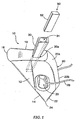
- FIG. 1 discloses one embodiment of a suture anchor system according to the present invention, the system being configured to allow a predetermined seating force to be applied on the suture anchor 10, by an insertion tool 50 engaged therewith, before the insertion tool 50 is removed from the suture anchor 10 following insertion thereof in the bore.
- a suture anchor 10 is described in, for example, U.S. Patent No. 6,306,158 to Bartlett , and generally comprises a quadrilaterally shaped body 12 having a maximum length surface 14, a leading edge 16, a separator surface 18, an upper width surface 20, a lower width surface 22, a trailing edge 24, and a suture bore 26.
- the maximum length surface 14 and the separator surface 18 intersect at an acute angle to form the leading edge 16.
- the maximum length surface 14 intersects with the lower width surface 22 at an acute angle to form the trailing edge 24.
- the separator surface 18 and the lower width surface 22 are further connected by the upper width surface 20, dispose generally opposite the maximum length surface 14 and comprising an arcuate portion 20a and a substantially linear portion 20b.
- the body 12 further defines a transverse suture bore 26 therethrough and through which a suture 28 extends.
- the leading edge 16 may be wide in order to distribute the anchoring stress over a greater surface area, as well as provide a more robust suture anchor 10.
- the separator surface 18 is generally a flat surface and has a separator extension 30 extending therefrom.
- the frangible portion 30a is configured with respect to, for example, shape, dimensions, and other factors, such that a tensile force of at least a predetermined magnitude may be applied on the separator extension 30 before breakage of the frangible portion 30a and separation of the separator extension 30 from the suture anchor 10 occurs.
- the separator extension 30 is configured so as to engage at least a portion of the tip 52 of the insertion tool 50 such that the separator extension 30 is secured to the tip 52, and the tip 52 extends into the body 12 of the suture anchor 10, for reasons which are further discussed below.
- the tip 52 /separator extension 30 interface is configured so as to be capable of withstanding a tensile force greater than the predetermined breaking strength of the frangible portion 30a.
- the tip 52 and the separator extension 30 may be configured to be separably engaged while having the necessary properties as discussed herein.
- the frangible portion 30a is configured to have a breaking strength no less than the predetermined required seating fore of the suture anchor 10 .
- the tip 52, the separator extension 30, and/or the body 12 are preferably configured to cooperate such that the separator extension 30 and body 12 are prevented from rotating about the axis of the tip 52.
- the tip 52 may have a generally square cross-section configured to engage a correspondingly square bore 31 defined by the separator extension 30 and the body 12.
- the tip 52 may be retained in the bore 31 through, for instance, a mechanical connection, adhesive, or other suitable mechanism, which may, in some instances, be combined with a friction fit configuration.
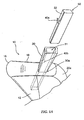
- a mechanism for retaining the tip 52 within the bore 31 is shown in FIG. 1A , wherein a first portion of the mechanism 40a engaged with the tip 52 cooperates with a second portion of the mechanism 40b engaged with the bore 31 when the tip 52 is inserted into the bore 31 to thereby retain the tip 52 in response to a tensile force exerted on the tip 52 outwardly of the bore 31 .
- the separator extension 30 may not necessarily extend entirely about the tip 52 as shown in FIG. 1 , but may only engage, for example, one, two, or three of the sides of a square tip 52, wherein the tip 52 /separator extension 30 interface is appropriately configured to accomplish the securing of the tip 52 to the separator extension as discussed herein.
- the body 12 will define the bore 31 for receiving the tip 52 if not readily apparent in the configuration of the separator extension 30.
- the separator extension 30 may define a tiered bore 31 for receiving a correspondingly shaped tip 52.
- the larger tier 31a of the bore 31 may extend only into the separator extension 30, while the smaller tier 31b of the bore 31 may extend through the separator extension 30 and the frangible portion 30a and into the body 12 of the suture anchor 10.
- the structure of the tip 52 and the corresponding receiving bore 31 may take many different forms capable of accomplishing the described purpose.
- the tip 52 may be tapered to engage a corresponding taper of the bore 31 extending into the body 12 .
- a suture anchor 10 according to the present invention is preferably biocompatible and, in some instances, is comprised of a bioabsorbable material, such as polylactic acid, polydioxanone, polyglycolic acid, and similar materials or blends thereof. Such materials should preferably be recognized by the appropriate regulatory authority as being suitable for use in humans. Additionally, it is desirable that the material strengthen the bone into which the anchor is inserted. It is further desirable for the material to be translucent or transparent to noninvasive examinations such as radiographs (e.g., X-rays). Accordingly, the suture anchor may also be comprised of cortical bone, where the bone may further be autologous or autogenous bone.
- the suture anchor may be comprised of a suitable biocompatible polymer, biocompatible metal, or other biocompatible material (see, e.g., U.S. Patent Nos. 5,540,718 , 5,626,612 , 5,782,863 , 5,871,503 , 5,879,372 , 6,146,408 , and 6,306,158 to Bartlett , U.S. Patent No. 5,683,418 to Luscombe et al ., and U.S. Patent No. 5,961,538 to Pedlick et al .).
- such suture anchors 10 as described herein may be formed by many different processes such as, for example, casting, machining, molding, or the like, as will be appreciated by one skilled in the art.
- the inserter bore 72 and the tip 52 have corresponding non-circular lateral cross-sections, such as generally square cross-sections having beveled or radiused corners, so as to prevent rotation of the suture anchor 10 about the axis of the tip 52.
- the tip 52 of the insertion tool 50 and the inserter bore 72 may have any corresponding shapes or configurations which minimize rotation of the suture anchor 10 about the axis of the tip 52.
- the suture anchor 10 may further define a tether bore 74 having a tether 76 extending therethrough.
- the tether 76 and the insertion tool 50 are configured such that the tether 76 is capable of engaging the insertion tool 50 so as to secure the tip 52 of the insertion tool 50 in engagement with the inserter bore 72 via the tether bore 74. In some instances, however, the tether 76 may secure the insertion tool to the suture anchor 10 via the suture bore 26. In either instance, the tether 76 may form a loop through the tether bore 74 /suture bore 26 and about the insertion tool 50, wherein the loop may be terminated with an appropriate knot 78 or other connector.
- the tip 52 of the insertion tool 50 is comprised of a material having elastic properties and, more preferably, superelastic properties, such as, for example, a shape memory material.
- the elastic or superelastic properties of the material should be such that the tip 52 is not substantially permanently deformed during insertion and implantation of the suture anchor 10, thereby allowing the tip 52 to substantially return to an initial configuration, namely the configuration of the tip 52 as it is initially inserted into the inserter bore 72.
- At least the tip 52 of the insertion tool 50 is comprised of a nickel-titanium alloy, such as is commercially available under the names NITINOLTM by Raychem, TINELTM by Raychem, or SENTINOLTM by GAC International Inc..
- a nickel-titanium alloy such as is commercially available under the names NITINOLTM by Raychem, TINELTM by Raychem, or SENTINOLTM by GAC International Inc.
- shape memory alloys having superelastic properties are well known in the art; however, any other shape retaining material sufficient for properly implanting the suture anchor 10 of the present invention in a bore in a bone may be used.
- the use of a shape memory material and the shape of the tip 52 which minimizes rotation of the suture anchor 10 about the tip 52 engaged therewith further allows a smaller sized tip 52 to be used to effectively implant the suture anchor 10 within a bone.
- a smaller sized tip 52 further allows a smaller suture anchor 10 to be used in situations where such is necessary or desired
- the suture anchor 10 may include a suture 28 engaged therewith through the suture bore 26.
- the suture bore 26 may vary in size and is preferably rounded or beveled around the openings in the body 12 in order to avoid abrasion of the suture 28.
- the inserter bore 72 is generally disposed intermediate the leading edge 16 and the suture bore 26. As described further herein, the inserter bore 72 cooperates with the insertion tool 50 to introduce the suture anchor 10 into a bore in a bone. As the suture anchor 10 is introduced into the bore, the maximum length surface 14 lies flush with the wall of the bore, with the insertion tool 50 imparting a force component sufficient to urge the maximum length surface 14 against the wall.
- the upper width surface 20 and, more specifically, the arcuate portion 20a, is thus disposed adjacent to the wall of the bore diametrically opposite the maximum length surface 14 .
- an axial separation force is then exerted on the insertion tool 50, outwardly of the bore, such that the separation force acts on the suture anchor to rotate the suture anchor 10 into a seated position in the bore.
- the suture anchor 10 generally requires a certain seating force to be exerted thereon to rotate the suture anchor 10 within the bore in the bone until a seated position is attained, wherein the seated position is up to about ninety degrees from the orientation in which the suture anchor 10 was initially inserted into the bore and the degree of rotation depends, at least in part, on the structure of the bone into which the suture anchor 10 is implanted.
- the tether 76 and/or the knot 78 are preferably configured to have a breaking strength, otherwise referred to herein as the separation force required to separate the insertion tool 50 from the suture anchor 10, of no less than the seating force for the suture anchor 10.
- the separation force may be slightly greater than the seating force, but less than the pullout strength of the suture anchor 10 itself, such that the suture anchor 10 can be checked for proper seating by repeated applications of the seating force before the tether 76 is broken and the insertion tool 50 removed from the suture anchor 10.
- suture anchors 10 as described herein are often configured to be seated in the bore such that the pullout strength, or the force required to extract a seated suture anchor 10 from the bore, approaches the tensile strength of the suture 28 threaded therethrough.
- the suture anchor 10 and attached suture 28 may be configured to withstand a force of up to about 1330N (30 pounds) without the suture anchor 10 pulling out of the bore or the suture 28 breaking. This relationship between the separation force and the seating force may also be applicable and beneficial to the embodiment illustrated in FIG. 1 and other embodiments of the present invention.
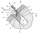
- FIGS. 3-10 illustrate a method of implanting a suture anchor 10 within a bore in a bone according to one embodiment of the present invention using an embodiment of a suture anchor system as illustrated in FIG. 2 .
- a bore is first drilled in the bone using a boring bit 54.
- the bore generally passes through an outer layer of dense bone (cortical layer) and into an inner layer of a less dense or osteoporotic bone (cancellous layer) further therein.
- the boring bit 54 is removed.
- the inserter bore 72 of a suture anchor 10 is then engaged with the tip 52 of the insertion tool 50, the suture anchor 10 including a suture 28 threaded through the suture bore 26.
- the suture anchor 10 is secured to the tip 52 or other portion of the insertion tool 50 by a tether 76 extending through the tether bore 74 to the insertion tool 50.
- the loose ends of the suture 28 are also held against the insertion tool 50 in order to prevent the suture 28 from becoming tangled or damaged during the insertion process.
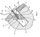
- the suture anchor 10 is then introduced into the bore such that the maximum length surface 14 is engaged with the wall of the bore. In this position, the insertion tool 50 is in its original configuration (substantially straight), with the tip 52 inserted in the inserter bore 72 and angled with respect to the axis of the bore. Further, as shown, the diameter of the bore roughly corresponds to the maximum width of the suture anchor 10.
- the maximum length surface 14 is preferably contacting the wall of the bore, while the point defining the maximum width of suture anchor 10 is at least within close proximity to the wall of the bore diametrically opposite the maximum length surface 14.
- a force directed inwardly with respect to the bore is then exerted on the insertion tool 50 such that the suture anchor 10 is urged into the bore.
- the force causes the insertion tool 50 to bend such that distal end of the tip 52 remains in the inserter bore 72, but the portion of the tip 52 outside of the suture anchor 10 bends or deforms to conform to the wall of the bore.
- a portion of the maximum length surface 14 is still in contact with the dense cortical bone layer since suture anchor 10 has not been inserted far enough into the bore for the leading edge 16 to pass by the cortical bone layer.
- the maximum length surface 14, aided by the force provided by the tip 52 of the insertion tool 50 remains flush against the wall of the bore.
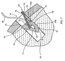
- FIG. 6 shows the suture anchor 10 after further force has been exerted on the insertion tool 50 inwardly with respect to the bore.
- the suture anchor 10 Once the suture anchor 10 has been inserted into the bore for a sufficient distance to clear the dense cortical surface layer of bone, it enters a less dense inner portion of the bone, namely the cancellous layer. Since the cancellous layer is less dense and weaker than cortical bone, the suture anchor 10 may begin to turn or rotate within the bore in response to force exerted by the tip 52 of the insertion tool 50 returning to its original shape due to the effect of the shape memory material from which it is comprised. As the rotation of -the suture anchor 10 occurs, the leading edge 16 is forced into the cancellous layer forming this portion of the wall of the bore.
- the arcuate portion 20a is urged against the wall of the of the bore, wherein engagement with the wall proceeds along the arcuate portion 20a to the linear portion 20b and then to the lower width surface 22 as the suture anchor 10 rotates.
- the suture anchor 10 generally begins to rotate about the point where the leading edge 16 engages the wall of the bore.
- the rotation of the suture anchor 10 may continue until the tip 52 of the insertion tool 50 has returned to its original shape such that the insertion tool 50 rests against the wall at the entrance to the bore.
- suture anchor 10 has been illustrated in this embodiment of a method of implantation as interacting with a bone structure having a cancellous layer underlying a cortical layer, such as that found, for example, in the "rotator cuff" area of the human shoulder (also known as the greater tuberosity of the humerus).
- a suture anchor 10 according to embodiments of the present invention may also be used in areas of dense bone, predominantly comprised of a cortical layer with an underlying cancellous layer having a relatively high density, such as, for example, at the "cup” or glenoid area of the shoulder. Note, however, that the density of the cancellous layer may vary greatly.
- a suture anchor 10 may tend not to rotate as freely or extensively within a cortical bone layer as within a cancellous layer, such a suture anchor 10 includes features further described herein which render the suture anchor 10 generally adapted for application to both dense cortical bone and less dense cancellous bone structures.
- further rotation of the suture anchor 10 may be obtained by exerting a rotational force on the insertion tool 50 so as to move the insertion tool 50 to the diametrically opposite side of the bore.
- the rotational force exerted on the insertion tool 50 causes the leading edge 16 to bite or penetrate further into the wall of the bore and the suture anchor 10 to rotate about the leading edge 16. That is, the rotation of the insertion tool 50 causes the suture anchor 10 to rotate about an axis perpendicular to the axis of the insertion tool 50. Accordingly, at the wall on the opposite side of the bore, the trailing edge 24 begins to penetrate into the wall of the bore.
- the rotation of the insertion tool 50 may also be accompanied by an axial force exerted on the insertion tool 50 outwardly of the bore.
- the insertion tool 50 is in contact with the wall on generally the opposite side of the bore from which the insertion tool 50 initially entered the bore.
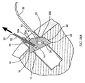
- the suture anchor 10 may not necessarily be in a seated position. Accordingly, an axial seating/separation force is then applied to the insertion tool 50, outwardly of the bore, so as to seat the suture anchor 10 , as shown in FIG. 9 .
- the tether 76 and/or the knot 78 are preferably configured to have a breaking strength, otherwise referred to herein as the separation force required to separate the insertion tool 50 from the suture anchor 10, of no less than the seating force for the suture anchor 10.
- the separation force may be slightly greater than the seating force, but less than the pullout strength of the suture anchor 10 itself, such that the suture anchor 10 can be checked for proper seating by repeated applications of the seating force before the tether 76 is broken and the insertion tool 50 removed from the suture anchor 10.
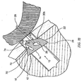
- FIG. 10A further illustrates the removal of the insertion tool 50, from a suture anchor 10 as shown in FIG. 1 , wherein a force at least as great as the required breaking strength of the frangible portion 30a is applied to the insertion tool 50 outwardly of the bore. Accordingly, the separator extension 30 is broken and separated from the suture anchor 10 at the frangible portion 30a when the force on the insertion tool 50 exceeds the breaking strength.
- embodiments of the present invention provide a suture anchor system having the desirable suture anchor implantation characteristics of a flexible insertion tool comprised of a shape memory material, while allowing a predetermined seating force to be applied on the suture anchor, by the insertion tool engaged therewith, before the insertion tool is removed from the suture anchor following insertion thereof in the bore, thereby providing predetermined and consistent seating characteristics of the suture anchor in the bone.
Landscapes
- Health & Medical Sciences (AREA)
- Surgery (AREA)
- Life Sciences & Earth Sciences (AREA)
- Medical Informatics (AREA)
- Animal Behavior & Ethology (AREA)
- Engineering & Computer Science (AREA)
- Biomedical Technology (AREA)
- Heart & Thoracic Surgery (AREA)
- Rheumatology (AREA)
- Molecular Biology (AREA)
- Nuclear Medicine, Radiotherapy & Molecular Imaging (AREA)
- General Health & Medical Sciences (AREA)
- Public Health (AREA)
- Veterinary Medicine (AREA)
- Surgical Instruments (AREA)
- Soil Working Implements (AREA)
- Joining Of Building Structures In Genera (AREA)
- Coating With Molten Metal (AREA)
Claims (15)
- Fadenankersystem, das so konfiguriert ist, dass es die Implantation eines Fadenankers (10) in einer in einem Knochen ausgebildeten Bohrung erleichtert, wobei die Bohrung eine Wand aufweist, um einen Faden (28) am Knochen zu befestigen, wobei das System Folgendes umfasst:einen Fadenanker (10), der geeignet ist, mit dem Faden (28) operativ in Eingriff gebracht zu werden, wobei der Fadenanker (10) eine vordere Kante (16) und eine hintere Kante (24) aufweist;ein Einführwerkzeug (50), das eine Spitze (52) aufweist und eine erste Achse definiert, wobei das Einführwerkzeug (50) relativ zum Fadenanker (10) separat ist und geeignet ist, den Fadenanker (10) so in der Bohrung implantieren zu können, dass der Fadenanker (10) im Knochen befestigt ist, wobei die Spitze (52) mit dem Fadenanker (10) in Eingriff gebracht werden kann und so konfiguriert ist, dass sie mit diesem zusammenwirkt, um zu verhindern, dass sich der Fadenanker (10) um die erste Achse dreht, wobei das Einführwerkzeug (50) bezüglich des Fadenankers (10) so konfiguriert ist, dass der Fadenanker (10) durch eine um eine zweite Achse auf das Einführwerkzeug (50) ausgeübte Drehkraft, wobei die zweite Achse senkrecht bezüglich der ersten Achse angeordnet ist, so um die zweite Achse gedreht wird, so dass die vordere und hintere Kante (16, 24) zunächst in die Wand der Bohrung eindringen,
dadurch gekennzeichnet, dass das Einführwerkzeug (50) am Fadenanker (10) befestigt ist, wobei der sichere Eingriff zwischen besagtem Einführwerkzeug und besagtem Fadenanker (10) so konfiguriert ist, dass eine vorbestimmte axiale Setzkraft, die ausserhalb der Bohrung auf das Einführwerkzeug (50) ausgeübt wird, die vordere und hintere Kante (16, 24) des Fadenankers (10) in der Wand der Bohrung weiter vorgeschoben werden, und zwar über das anfängliche Eindringen hinaus, um dadurch den Fadenanker (10) so im der Bohrung zu platzieren, ohne den sicheren Eingriff zwischen dem Einführwerkzeug (50) und dem Fadenanker (10) zu lösen, und dass durch eine ebenfalls ausserhalb der Bohrung auf das Einführwerkzeug (50) ausgeübte axiale Trennkraft, nach dem Einsetzen des Fadenanker (10) in der Bohrung durch Aufbringung der Setzkraft auf das Einführwerkzeug (50), der sichere Eingriff zwischen dem Einführwerkzeug (50) und dem Fadenanker (10) gelöst wird, und dadurch das Einführwerkzeug (50) vom Fadenanker (10) getrennt wird, wobei der sichere Eingriff zwischen dem Einführwerkzeug (50) und dem Fadenanker (10) so ist, dass die Trennkraft, die zum Lösen des sicheren Eingriffs zwischen dem Einführwerkzeug (50) und dem Fadenanker (10) auf das Einführwerkzeug (50) ausgeübt werden muss, nicht geringer ist als die Setzkraft, die vom Einführwerkzeug (50) auf den Fadenanker (10) ausgeübt werden muss, um den Fadenanker (10) in der Bohrung zu platzieren. - System nach Anspruch 1, dadurch gekennzeichnet, dass die Spitze (52) des Einführwerkzeugs (50) so konfiguriert ist, dass sie von einer Trennelementverlängerung (30) aufgenommen und sicher damit in Eingriff gebracht wird, wobei die Trennelementverlängerung (30) mit dem Fadenanker (10) durch einen dazwischen liegenden zerbrechlichen Teil (30a) in Verbindung steht, wobei der zerbrechliche Teil (30a) den Eingriff bildet, der so konfiguriert ist, dass er sich bei nicht weniger als der Setzkraft löst.
- System nach Anspruch 1, dadurch gekennzeichnet, dass, ein eine Anbindung (76) fest zwischen dem Fadenanker (10) und dem Einführwerkzeug (50) befestigt ist und so den Eingriff bildet, der so konfiguriert ist, dass er sich bei nicht weniger als der Setzkraft löst.
- System nach einem der Ansprüche 1 bis 3, dadurch gekennzeichnet, dass der Fadenanker (10) aus mindestens einem bioverträglichen oder einem bioresorbierbaren Material besteht.
- System nach einem der Ansprüche 1 bis 3, dadurch gekennzeichnet, dass der Fadenanker (10) aus mindestens einem Element aus einer Polymilchsäure, einem Polydioxanon und einer Polyglykolsäure besteht.
- System nach einem der Ansprüche 1 bis 3, dadurch gekennzeichnet, dass zumindest die Spitze (52) des Einführwerkzeugs (50) aus einem Formgedächtnismetall besteht.
- System nach einem der Ansprüche 1 bis 3, dadurch gekennzeichnet, dass zumindest die Spitze (52) des Einführwerkzeugs (50) aus einer Nickel-TitanLegierung besteht.
- System nach Anspruche 1 oder Anspruch 3, dadurch gekennzeichnet, dass der Fadenanker (10) eine Bohrung (31, 72) mit einem nicht kreisförmigen Querschnitt definiert, wobei die Bohrung (31, 72) so konfiguriert ist, dass sie die Spitze (52) des Einführwerkzeugs (50) aufnimmt, wobei die Spitze (52) einen nicht kreisförmigen Querschnitt entsprechend der Bohrung (31, 72) aufweist, so dass die Spitze (52) in der Lage ist, mit der Bohrung (31, 72) zusammenzuwirken, um zu verhindern, dass sich der Fadenanker (10) um die erste Achse dreht.
- System nach Anspruch 2, dadurch gekennzeichnet, dass der Fadenanker (10), der zerbrechliche Teil (30a) und die Trennelementverlärigerung (30) vorzugsweise in einem Spritzgussverfahren einstückig geformt sind.
- System nach Anspruch 2, dadurch gekennzeichnet, dass die Spitze (52) des Einführwerkzeugs (50) so konfiguriert ist, dass die Trennelementverlängerung (30) davon getrennt werden kann.
- System nach Anspruch 3, dadurch gekennzeichnet, dass der Fadenanker (10) ferner eine Hilfsbohrung (74) definiert, die so konfiguriert ist, dass sie die Anbindung (76) durch sie hindurch aufnimmt.
- System nach Anspruch 3, dadurch gekennzeichnet, dass zumindest das Einführwerkzeug (50) oder die Spitze (52) so konfiguriert ist, dass das die Anbindung (76) daran befestigt werden kann.
- System nach Anspruch 3, dadurch gekennzeichnet, dass die Anbindung (76) als Schlaufe konfiguriert ist, die sich durch eine durch den Fadenanker (10) definierte Bohrung (72) und eine durch das Einführwerkzeug (50) definierte Bohrung erstreckt, wobei die Schlaufe einen Knoten (78) umfasst, der so konfiguriert ist, dass er sich bei nicht weniger als der Setzkraft löst.
- System nach Anspruch 3, dadurch gekennzeichnet, dass die vom Fadenanker (10) definierte Bohrung (72) so konfiguriert ist, dass sie nach dem Entfernen des Einführwerkzeugs (50) aus dem Fadenanker (10) das Entfernen der gelösten Anbindung (76) erleichtert.
- System nach Anspruch 3, dadurch gekennzeichnet, dass die Anbindung (76) einen Faden (28) umfasst.
Applications Claiming Priority (2)
| Application Number | Priority Date | Filing Date | Title |
|---|---|---|---|
| US10/105,807 US6843799B2 (en) | 2002-03-25 | 2002-03-25 | Suture anchor system and associated method |
| EP03745514A EP1487351B1 (de) | 2002-03-25 | 2003-02-13 | Nahtankersystem |
Related Parent Applications (2)
| Application Number | Title | Priority Date | Filing Date |
|---|---|---|---|
| EP03745514A Division EP1487351B1 (de) | 2002-03-25 | 2003-02-13 | Nahtankersystem |
| EP03745514.4 Division | 2003-02-13 |
Publications (2)
| Publication Number | Publication Date |
|---|---|
| EP2055239A1 EP2055239A1 (de) | 2009-05-06 |
| EP2055239B1 true EP2055239B1 (de) | 2012-02-01 |
Family
ID=28040863
Family Applications (2)
| Application Number | Title | Priority Date | Filing Date |
|---|---|---|---|
| EP09001728A Expired - Lifetime EP2055239B1 (de) | 2002-03-25 | 2003-02-13 | Nahtankersystem und zugehöriges Verfahren |
| EP03745514A Expired - Lifetime EP1487351B1 (de) | 2002-03-25 | 2003-02-13 | Nahtankersystem |
Family Applications After (1)
| Application Number | Title | Priority Date | Filing Date |
|---|---|---|---|
| EP03745514A Expired - Lifetime EP1487351B1 (de) | 2002-03-25 | 2003-02-13 | Nahtankersystem |
Country Status (8)
| Country | Link |
|---|---|
| US (1) | US6843799B2 (de) |
| EP (2) | EP2055239B1 (de) |
| JP (1) | JP4184979B2 (de) |
| AT (2) | ATE543440T1 (de) |
| AU (1) | AU2003211031C1 (de) |
| CA (1) | CA2479436C (de) |
| DE (1) | DE60326942D1 (de) |
| WO (1) | WO2003082124A1 (de) |
Cited By (1)
| Publication number | Priority date | Publication date | Assignee | Title |
|---|---|---|---|---|
| WO2024076686A1 (en) * | 2022-10-06 | 2024-04-11 | INTERNATIONAL LIFE SCIENCES, LLC d/b/a ARTELON | Surgical anchors, instrumentation, and methods of use |
Families Citing this family (38)
| Publication number | Priority date | Publication date | Assignee | Title |
|---|---|---|---|---|
| US8128698B2 (en) | 1999-10-20 | 2012-03-06 | Anulex Technologies, Inc. | Method and apparatus for the treatment of the intervertebral disc annulus |
| US8632590B2 (en) | 1999-10-20 | 2014-01-21 | Anulex Technologies, Inc. | Apparatus and methods for the treatment of the intervertebral disc |
| US20030153976A1 (en) * | 1999-10-20 | 2003-08-14 | Cauthen Joseph C. | Spinal disc annulus reconstruction method and spinal disc annulus stent |
| US7615076B2 (en) | 1999-10-20 | 2009-11-10 | Anulex Technologies, Inc. | Method and apparatus for the treatment of the intervertebral disc annulus |
| US7004970B2 (en) | 1999-10-20 | 2006-02-28 | Anulex Technologies, Inc. | Methods and devices for spinal disc annulus reconstruction and repair |
| ATE460885T1 (de) * | 2002-08-01 | 2010-04-15 | Abbott Lab Vascular Entpr Ltd | Gerät zur abdichtung von punktionsstellen in blutgefässen |
| US7320701B2 (en) * | 2003-06-02 | 2008-01-22 | Linvatec Corporation | Push-in suture anchor, insertion tool, and method for inserting a push-in suture anchor |
| US20050090827A1 (en) * | 2003-10-28 | 2005-04-28 | Tewodros Gedebou | Comprehensive tissue attachment system |
| US20050096696A1 (en) * | 2003-11-04 | 2005-05-05 | Forsberg Andrew T. | Arteriotomy closure device with anti-roll anchor |
| GB0329654D0 (en) * | 2003-12-23 | 2004-01-28 | Smith & Nephew | Tunable segmented polyacetal |
| FR2871361B1 (fr) * | 2004-06-15 | 2006-09-29 | Analytic Biosurgical Solutions | Dispositif d'ancrage chirurgical |
| US20060229671A1 (en) * | 2005-04-08 | 2006-10-12 | Musculoskeletal Transplant Foundation | Suture anchor and suture anchor installation tool |
| CN101594831B (zh) * | 2006-11-30 | 2011-09-14 | 史密夫和内修有限公司 | 纤维增强的复合材料 |
| US20080177288A1 (en) * | 2007-01-19 | 2008-07-24 | Carlson Mark A | Remote Suturing Device |
| WO2008129245A1 (en) | 2007-04-18 | 2008-10-30 | Smith & Nephew Plc | Expansion moulding of shape memory polymers |
| DE602008006181D1 (de) | 2007-04-19 | 2011-05-26 | Smith & Nephew Inc | Graft-fixierung |
| ATE547129T1 (de) | 2007-04-19 | 2012-03-15 | Smith & Nephew Inc | Multimodale formgedächtnis-polymere |
| US9095384B2 (en) * | 2007-10-17 | 2015-08-04 | Aro Medical Aps U/Stiftelse | Methods, systems and apparatuses for torsional stabilization |
| US8163022B2 (en) | 2008-10-14 | 2012-04-24 | Anulex Technologies, Inc. | Method and apparatus for the treatment of the intervertebral disc annulus |
| US9717581B2 (en) * | 2009-02-05 | 2017-08-01 | Coloplast A/S | Incontinence treatment device including a system of anchors |
| US11219515B2 (en) | 2009-02-05 | 2022-01-11 | Coloplast A/S | Incontinence treatment device having a first anchor assembly and a second anchor assembly |
| US8226685B2 (en) * | 2009-08-25 | 2012-07-24 | Redline Orthopedic Innovations, Llc | Suture anchor and method of use |
| US8460319B2 (en) | 2010-01-11 | 2013-06-11 | Anulex Technologies, Inc. | Intervertebral disc annulus repair system and method |
| US8425611B2 (en) | 2010-10-26 | 2013-04-23 | Warsaw Orthopedic, Inc. | Expandable orthopedic implant system and method |
| US9204959B2 (en) * | 2012-02-02 | 2015-12-08 | Smith & Nephew, Inc. | Implantable biologic holder |
| US9737294B2 (en) | 2013-01-28 | 2017-08-22 | Cartiva, Inc. | Method and system for orthopedic repair |
| WO2014117107A1 (en) | 2013-01-28 | 2014-07-31 | Cartiva, Inc. | Systems and methods for orthopedic repair |
| ES3029211T3 (en) | 2017-01-16 | 2025-06-23 | Coloplast As | Sacrocolpopexy support |
| US10722343B2 (en) * | 2017-02-22 | 2020-07-28 | Stryker Corporation | Fixation member with separate eyelet and methods of use thereof |
| WO2020096861A1 (en) * | 2018-11-08 | 2020-05-14 | Edwards Lifesciences Corporation | Percutaneous anchoring for treatment of heart failure with reduced ejection fraction |
| US12226307B2 (en) | 2021-04-08 | 2025-02-18 | Integrity Orthopaedics, Inc. | Individually lockable cinch loop micro suture anchor array for high density anatomical attachment of soft tissue to bone |
| US11375995B1 (en) | 2021-04-08 | 2022-07-05 | Integrity Orthopaedics, Inc. | Locking suture construct for tensioned suture to suture stitches in anchor arrays for attaching soft tissue to bone |
| US11375992B1 (en) | 2021-04-08 | 2022-07-05 | Integrity Orthopaedics, Inc. | Cartridge device for suture anchor and suture management during implantation of a micro suture anchor array |
| US12396839B2 (en) | 2021-04-08 | 2025-08-26 | Integrity Orthopaedics, Inc. | Method and apparatus for creating a seam-like anatomical low creep attachment of soft tissue to bone |
| US12453545B2 (en) | 2021-04-08 | 2025-10-28 | Integrity Orthopaedics, Inc. | Tensionable and lockable soft suture anchors and anchor arrays for anatomical attachment of soft tissue to bone |
| US11382613B1 (en) | 2021-04-08 | 2022-07-12 | Integrity Orthopaedics, Inc. | Methods for transtendinous implantation of knotless micro suture anchors and anchor arrays |
| US11382612B1 (en) | 2021-04-08 | 2022-07-12 | Integrity Orthopaedics, Inc. | Method for creating a tensionable and lockable suture anchor array for anatomical attachment of tissue to bone |
| US11375991B1 (en) | 2021-04-08 | 2022-07-05 | Integrity Orthopaedics, Inc. | Tensionable and lockable micro suture anchors and anchor arrays for anatomical attachment of soft tissue to bone |
Family Cites Families (29)
| Publication number | Priority date | Publication date | Assignee | Title |
|---|---|---|---|---|
| US5601557A (en) | 1982-05-20 | 1997-02-11 | Hayhurst; John O. | Anchoring and manipulating tissue |
| US4669473A (en) | 1985-09-06 | 1987-06-02 | Acufex Microsurgical, Inc. | Surgical fastener |
| US4946468A (en) | 1989-06-06 | 1990-08-07 | Mitek Surgical Products, Inc. | Suture anchor and suture anchor installation tool |
| US5102421A (en) | 1990-06-14 | 1992-04-07 | Wm. E. Anpach, III | Suture anchor and method of forming |
| US5269809A (en) | 1990-07-02 | 1993-12-14 | American Cyanamid Company | Locking mechanism for use with a slotted suture anchor |
| US5258016A (en) | 1990-07-13 | 1993-11-02 | American Cyanamid Company | Suture anchor and driver assembly |
| US5085661A (en) | 1990-10-29 | 1992-02-04 | Gerald Moss | Surgical fastener implantation device |
| US5203787A (en) | 1990-11-19 | 1993-04-20 | Biomet, Inc. | Suture retaining arrangement |
| US5354298A (en) | 1991-03-22 | 1994-10-11 | United States Surgical Corporation | Suture anchor installation system |
| US5207679A (en) | 1991-09-26 | 1993-05-04 | Mitek Surgical Products, Inc. | Suture anchor and installation tool |
| US5868789A (en) | 1997-02-03 | 1999-02-09 | Huebner; Randall J. | Removable suture anchor apparatus |
| US5814073A (en) | 1996-12-13 | 1998-09-29 | Bonutti; Peter M. | Method and apparatus for positioning a suture anchor |
| US5423860A (en) | 1993-05-28 | 1995-06-13 | American Cyanamid Company | Protective carrier for suture anchor |
| US5522844A (en) | 1993-06-22 | 1996-06-04 | Johnson; Lanny L. | Suture anchor, suture anchor installation device and method for attaching a suture to a bone |
| US5540718A (en) | 1993-09-20 | 1996-07-30 | Bartlett; Edwin C. | Apparatus and method for anchoring sutures |
| US5584835A (en) | 1993-10-18 | 1996-12-17 | Greenfield; Jon B. | Soft tissue to bone fixation device and method |
| US5405359A (en) | 1994-04-29 | 1995-04-11 | Pierce; Javi | Toggle wedge |
| US5466243A (en) | 1994-02-17 | 1995-11-14 | Arthrex, Inc. | Method and apparatus for installing a suture anchor through a hollow cannulated grasper |
| US5464425A (en) | 1994-02-23 | 1995-11-07 | Orthopaedic Biosystems, Ltd. | Medullary suture anchor |
| US5683418A (en) | 1994-04-29 | 1997-11-04 | Mitek Surgical Products, Inc. | Wedge shaped suture anchor and method of implantation |
| US5814071A (en) | 1994-11-10 | 1998-09-29 | Innovasive Devices, Inc. | Suture anchor assembly and methods |
| US5626613A (en) | 1995-05-04 | 1997-05-06 | Arthrex, Inc. | Corkscrew suture anchor and driver |
| US5814070A (en) | 1996-02-20 | 1998-09-29 | Howmedica Inc. | Suture anchor and driver |
| US5961538A (en) | 1996-04-10 | 1999-10-05 | Mitek Surgical Products, Inc. | Wedge shaped suture anchor and method of implantation |
| US5782862A (en) | 1996-07-01 | 1998-07-21 | Bonutti; Peter M. | Suture anchor inserter assembly and method |
| US5814072A (en) | 1996-11-15 | 1998-09-29 | Bonutti; Peter M. | Method and apparatus for use in anchoring a suture |
| US5709708A (en) | 1997-01-31 | 1998-01-20 | Thal; Raymond | Captured-loop knotless suture anchor assembly |
| US5814051A (en) | 1997-06-06 | 1998-09-29 | Mitex Surgical Products, Inc. | Suture anchor insertion system |
| US6306158B1 (en) | 1999-03-02 | 2001-10-23 | Edwin C. Bartlett | Suture anchor and associated method of implantation |
-
2002
- 2002-03-25 US US10/105,807 patent/US6843799B2/en not_active Expired - Lifetime
-
2003
- 2003-02-13 AT AT09001728T patent/ATE543440T1/de active
- 2003-02-13 WO PCT/US2003/004367 patent/WO2003082124A1/en not_active Ceased
- 2003-02-13 AU AU2003211031A patent/AU2003211031C1/en not_active Expired
- 2003-02-13 JP JP2003579671A patent/JP4184979B2/ja not_active Expired - Lifetime
- 2003-02-13 EP EP09001728A patent/EP2055239B1/de not_active Expired - Lifetime
- 2003-02-13 CA CA002479436A patent/CA2479436C/en not_active Expired - Fee Related
- 2003-02-13 DE DE60326942T patent/DE60326942D1/de not_active Expired - Lifetime
- 2003-02-13 AT AT03745514T patent/ATE427071T1/de not_active IP Right Cessation
- 2003-02-13 EP EP03745514A patent/EP1487351B1/de not_active Expired - Lifetime
Cited By (1)
| Publication number | Priority date | Publication date | Assignee | Title |
|---|---|---|---|---|
| WO2024076686A1 (en) * | 2022-10-06 | 2024-04-11 | INTERNATIONAL LIFE SCIENCES, LLC d/b/a ARTELON | Surgical anchors, instrumentation, and methods of use |
Also Published As
| Publication number | Publication date |
|---|---|
| EP2055239A1 (de) | 2009-05-06 |
| JP4184979B2 (ja) | 2008-11-19 |
| AU2003211031C1 (en) | 2008-10-09 |
| EP1487351A1 (de) | 2004-12-22 |
| CA2479436A1 (en) | 2003-10-09 |
| AU2003211031A1 (en) | 2003-10-13 |
| WO2003082124A1 (en) | 2003-10-09 |
| EP1487351B1 (de) | 2009-04-01 |
| ATE427071T1 (de) | 2009-04-15 |
| ATE543440T1 (de) | 2012-02-15 |
| JP2005521462A (ja) | 2005-07-21 |
| US6843799B2 (en) | 2005-01-18 |
| US20030181946A1 (en) | 2003-09-25 |
| CA2479436C (en) | 2008-01-08 |
| AU2003211031B2 (en) | 2008-04-03 |
| DE60326942D1 (de) | 2009-05-14 |
Similar Documents
| Publication | Publication Date | Title |
|---|---|---|
| EP1487351B1 (de) | Nahtankersystem | |
| EP1156743B1 (de) | Nähfadenanker | |
| JP4717379B2 (ja) | 改善された駆動ヘッドを伴う縫合糸固定装置 | |
| US6022373A (en) | Surgical anchor and package and cartridge for surgical anchor | |
| US7041120B2 (en) | Toggle anchor and tool for insertion thereof | |
| US5690649A (en) | Anchor and anchor installation tool and method | |
| JP2002520115A (ja) | 特に板貫通形椎骨ねじ止めの際の使用のための骨締結ねじ | |
| AU2004202440A1 (en) | Push-in suture anchor, insertion tool, and method for inserting a push-in suture anchor | |
| KR20170093915A (ko) | 앵커 삽입기를 가지는 2-부분 앵커 | |
| US20070135816A1 (en) | Bone anchor | |
| AU2003204846B2 (en) | Suture Anchor and Associated Method of Implantation |
Legal Events
| Date | Code | Title | Description |
|---|---|---|---|
| PUAI | Public reference made under article 153(3) epc to a published international application that has entered the european phase |
Free format text: ORIGINAL CODE: 0009012 |
|
| AC | Divisional application: reference to earlier application |
Ref document number: 1487351 Country of ref document: EP Kind code of ref document: P |
|
| AK | Designated contracting states |
Kind code of ref document: A1 Designated state(s): DE FR GB |
|
| 17P | Request for examination filed |
Effective date: 20091105 |
|
| AKX | Designation fees paid |
Designated state(s): AT BE BG CH CY CZ DE DK EE ES FI FR GB GR HU IE IT LI LU MC NL PT SE SI SK TR |
|
| 17Q | First examination report despatched |
Effective date: 20100126 |
|
| GRAP | Despatch of communication of intention to grant a patent |
Free format text: ORIGINAL CODE: EPIDOSNIGR1 |
|
| RAP1 | Party data changed (applicant data changed or rights of an application transferred) |
Owner name: BARTLETT, EDWIN C. |
|
| RIN1 | Information on inventor provided before grant (corrected) |
Inventor name: BARTLETT, EDWIN C. |
|
| GRAS | Grant fee paid |
Free format text: ORIGINAL CODE: EPIDOSNIGR3 |
|
| GRAA | (expected) grant |
Free format text: ORIGINAL CODE: 0009210 |
|
| AC | Divisional application: reference to earlier application |
Ref document number: 1487351 Country of ref document: EP Kind code of ref document: P |
|
| AK | Designated contracting states |
Kind code of ref document: B1 Designated state(s): AT BE BG CH CY CZ DE DK EE ES FI FR GB GR HU IE IT LI LU MC NL PT SE SI SK TR |
|
| REG | Reference to a national code |
Ref country code: GB Ref legal event code: FG4D |
|
| REG | Reference to a national code |
Ref country code: CH Ref legal event code: EP Ref country code: AT Ref legal event code: REF Ref document number: 543440 Country of ref document: AT Kind code of ref document: T Effective date: 20120215 |
|
| REG | Reference to a national code |
Ref country code: DE Ref legal event code: R096 Ref document number: 60339933 Country of ref document: DE Effective date: 20120329 |
|
| REG | Reference to a national code |
Ref country code: NL Ref legal event code: VDEP Effective date: 20120201 |
|
| PG25 | Lapsed in a contracting state [announced via postgrant information from national office to epo] |
Ref country code: NL Free format text: LAPSE BECAUSE OF FAILURE TO SUBMIT A TRANSLATION OF THE DESCRIPTION OR TO PAY THE FEE WITHIN THE PRESCRIBED TIME-LIMIT Effective date: 20120201 |
|
| PG25 | Lapsed in a contracting state [announced via postgrant information from national office to epo] |
Ref country code: FI Free format text: LAPSE BECAUSE OF FAILURE TO SUBMIT A TRANSLATION OF THE DESCRIPTION OR TO PAY THE FEE WITHIN THE PRESCRIBED TIME-LIMIT Effective date: 20120201 Ref country code: BE Free format text: LAPSE BECAUSE OF FAILURE TO SUBMIT A TRANSLATION OF THE DESCRIPTION OR TO PAY THE FEE WITHIN THE PRESCRIBED TIME-LIMIT Effective date: 20120201 Ref country code: GR Free format text: LAPSE BECAUSE OF FAILURE TO SUBMIT A TRANSLATION OF THE DESCRIPTION OR TO PAY THE FEE WITHIN THE PRESCRIBED TIME-LIMIT Effective date: 20120502 |
|
| REG | Reference to a national code |
Ref country code: AT Ref legal event code: MK05 Ref document number: 543440 Country of ref document: AT Kind code of ref document: T Effective date: 20120201 |
|
| PG25 | Lapsed in a contracting state [announced via postgrant information from national office to epo] |
Ref country code: MC Free format text: LAPSE BECAUSE OF NON-PAYMENT OF DUE FEES Effective date: 20120229 Ref country code: CY Free format text: LAPSE BECAUSE OF FAILURE TO SUBMIT A TRANSLATION OF THE DESCRIPTION OR TO PAY THE FEE WITHIN THE PRESCRIBED TIME-LIMIT Effective date: 20120201 |
|
| REG | Reference to a national code |
Ref country code: CH Ref legal event code: PL |
|
| PG25 | Lapsed in a contracting state [announced via postgrant information from national office to epo] |
Ref country code: SI Free format text: LAPSE BECAUSE OF FAILURE TO SUBMIT A TRANSLATION OF THE DESCRIPTION OR TO PAY THE FEE WITHIN THE PRESCRIBED TIME-LIMIT Effective date: 20120201 Ref country code: SE Free format text: LAPSE BECAUSE OF FAILURE TO SUBMIT A TRANSLATION OF THE DESCRIPTION OR TO PAY THE FEE WITHIN THE PRESCRIBED TIME-LIMIT Effective date: 20120201 Ref country code: DK Free format text: LAPSE BECAUSE OF FAILURE TO SUBMIT A TRANSLATION OF THE DESCRIPTION OR TO PAY THE FEE WITHIN THE PRESCRIBED TIME-LIMIT Effective date: 20120201 Ref country code: CH Free format text: LAPSE BECAUSE OF NON-PAYMENT OF DUE FEES Effective date: 20120229 Ref country code: LI Free format text: LAPSE BECAUSE OF NON-PAYMENT OF DUE FEES Effective date: 20120229 Ref country code: CZ Free format text: LAPSE BECAUSE OF FAILURE TO SUBMIT A TRANSLATION OF THE DESCRIPTION OR TO PAY THE FEE WITHIN THE PRESCRIBED TIME-LIMIT Effective date: 20120201 Ref country code: EE Free format text: LAPSE BECAUSE OF FAILURE TO SUBMIT A TRANSLATION OF THE DESCRIPTION OR TO PAY THE FEE WITHIN THE PRESCRIBED TIME-LIMIT Effective date: 20120201 |
|
| REG | Reference to a national code |
Ref country code: IE Ref legal event code: MM4A |
|
| PG25 | Lapsed in a contracting state [announced via postgrant information from national office to epo] |
Ref country code: SK Free format text: LAPSE BECAUSE OF FAILURE TO SUBMIT A TRANSLATION OF THE DESCRIPTION OR TO PAY THE FEE WITHIN THE PRESCRIBED TIME-LIMIT Effective date: 20120201 |
|
| PLBE | No opposition filed within time limit |
Free format text: ORIGINAL CODE: 0009261 |
|
| STAA | Information on the status of an ep patent application or granted ep patent |
Free format text: STATUS: NO OPPOSITION FILED WITHIN TIME LIMIT |
|
| 26N | No opposition filed |
Effective date: 20121105 |
|
| PG25 | Lapsed in a contracting state [announced via postgrant information from national office to epo] |
Ref country code: AT Free format text: LAPSE BECAUSE OF FAILURE TO SUBMIT A TRANSLATION OF THE DESCRIPTION OR TO PAY THE FEE WITHIN THE PRESCRIBED TIME-LIMIT Effective date: 20120201 Ref country code: IE Free format text: LAPSE BECAUSE OF NON-PAYMENT OF DUE FEES Effective date: 20120213 |
|
| REG | Reference to a national code |
Ref country code: DE Ref legal event code: R097 Ref document number: 60339933 Country of ref document: DE Effective date: 20121105 |
|
| PG25 | Lapsed in a contracting state [announced via postgrant information from national office to epo] |
Ref country code: BG Free format text: LAPSE BECAUSE OF FAILURE TO SUBMIT A TRANSLATION OF THE DESCRIPTION OR TO PAY THE FEE WITHIN THE PRESCRIBED TIME-LIMIT Effective date: 20120501 |
|
| PG25 | Lapsed in a contracting state [announced via postgrant information from national office to epo] |
Ref country code: TR Free format text: LAPSE BECAUSE OF FAILURE TO SUBMIT A TRANSLATION OF THE DESCRIPTION OR TO PAY THE FEE WITHIN THE PRESCRIBED TIME-LIMIT Effective date: 20120201 |
|
| PG25 | Lapsed in a contracting state [announced via postgrant information from national office to epo] |
Ref country code: ES Free format text: LAPSE BECAUSE OF FAILURE TO SUBMIT A TRANSLATION OF THE DESCRIPTION OR TO PAY THE FEE WITHIN THE PRESCRIBED TIME-LIMIT Effective date: 20120201 Ref country code: LU Free format text: LAPSE BECAUSE OF NON-PAYMENT OF DUE FEES Effective date: 20120213 |
|
| PG25 | Lapsed in a contracting state [announced via postgrant information from national office to epo] |
Ref country code: PT Free format text: LAPSE BECAUSE OF FAILURE TO SUBMIT A TRANSLATION OF THE DESCRIPTION OR TO PAY THE FEE WITHIN THE PRESCRIBED TIME-LIMIT Effective date: 20120201 Ref country code: HU Free format text: LAPSE BECAUSE OF FAILURE TO SUBMIT A TRANSLATION OF THE DESCRIPTION OR TO PAY THE FEE WITHIN THE PRESCRIBED TIME-LIMIT Effective date: 20030213 |
|
| REG | Reference to a national code |
Ref country code: FR Ref legal event code: PLFP Year of fee payment: 14 |
|
| REG | Reference to a national code |
Ref country code: FR Ref legal event code: PLFP Year of fee payment: 15 |
|
| REG | Reference to a national code |
Ref country code: FR Ref legal event code: PLFP Year of fee payment: 16 |
|
| PGFP | Annual fee paid to national office [announced via postgrant information from national office to epo] |
Ref country code: GB Payment date: 20211230 Year of fee payment: 20 |
|
| PGFP | Annual fee paid to national office [announced via postgrant information from national office to epo] |
Ref country code: DE Payment date: 20211230 Year of fee payment: 20 |
|
| PGFP | Annual fee paid to national office [announced via postgrant information from national office to epo] |
Ref country code: IT Payment date: 20220111 Year of fee payment: 20 Ref country code: FR Payment date: 20220118 Year of fee payment: 20 |
|
| REG | Reference to a national code |
Ref country code: DE Ref legal event code: R071 Ref document number: 60339933 Country of ref document: DE |
|
| REG | Reference to a national code |
Ref country code: GB Ref legal event code: PE20 Expiry date: 20230212 |
|
| PG25 | Lapsed in a contracting state [announced via postgrant information from national office to epo] |
Ref country code: GB Free format text: LAPSE BECAUSE OF EXPIRATION OF PROTECTION Effective date: 20230212 |