EP2055398A2 - Mobiler Abzug - Google Patents
Mobiler Abzug Download PDFInfo
- Publication number
- EP2055398A2 EP2055398A2 EP09151454A EP09151454A EP2055398A2 EP 2055398 A2 EP2055398 A2 EP 2055398A2 EP 09151454 A EP09151454 A EP 09151454A EP 09151454 A EP09151454 A EP 09151454A EP 2055398 A2 EP2055398 A2 EP 2055398A2
- Authority
- EP
- European Patent Office
- Prior art keywords
- trigger
- media
- working space
- exhaust air
- connection
- Prior art date
- Legal status (The legal status is an assumption and is not a legal conclusion. Google has not performed a legal analysis and makes no representation as to the accuracy of the status listed.)
- Granted
Links
Images


Classifications
-
- B—PERFORMING OPERATIONS; TRANSPORTING
- B01—PHYSICAL OR CHEMICAL PROCESSES OR APPARATUS IN GENERAL
- B01L—CHEMICAL OR PHYSICAL LABORATORY APPARATUS FOR GENERAL USE
- B01L9/00—Supporting devices; Holding devices
- B01L9/02—Laboratory benches or tables; Fittings therefor
-
- B—PERFORMING OPERATIONS; TRANSPORTING
- B08—CLEANING
- B08B—CLEANING IN GENERAL; PREVENTION OF FOULING IN GENERAL
- B08B15/00—Preventing escape of dirt or fumes from the area where they are produced; Collecting or removing dirt or fumes from that area
- B08B15/02—Preventing escape of dirt or fumes from the area where they are produced; Collecting or removing dirt or fumes from that area using chambers or hoods covering the area
- B08B15/023—Fume cabinets or cupboards, e.g. for laboratories
-
- B—PERFORMING OPERATIONS; TRANSPORTING
- B25—HAND TOOLS; PORTABLE POWER-DRIVEN TOOLS; MANIPULATORS
- B25H—WORKSHOP EQUIPMENT, e.g. FOR MARKING-OUT WORK; STORAGE MEANS FOR WORKSHOPS
- B25H1/00—Work benches; Portable stands or supports for positioning portable tools or work to be operated on thereby
- B25H1/20—Work benches; Portable stands or supports for positioning portable tools or work to be operated on thereby with provision for shielding the work area
Definitions
- the invention relates to a mobile trigger with a working space, a media connection device for supplying media to the working space and an exhaust air connection device.
- the object underlying the invention is to provide a mobile trigger of the type mentioned, the full value, that is equivalent to a stationary standard deduction in terms of its functions, and meets the corresponding German industrial standard.
- the media connection device comprises a complete set of media connections for all common media in standard fume hoods and the media connection device and the exhaust device are provided with flexible connection hoses, which consist of the trigger lower part lead out and are provided with couplings for connection to appropriate stationary facilities.
- the mobile trigger according to the invention thus has in particular media connections for the media sewage, gas, water and electrical energy as well as an exhaust air connection, which have heretofore been provided only as a complete equipment for stationary, floor-mounted fume hoods.
- connection possibilities of the mobile trigger are optionally depending on the possible where the supply device is prepared by the customer. This can be the case on the floor, on the wall or on the ceiling. Due to the flexible connection lines, the mobile trigger is still movable even when already connected, wherein the mobility is achieved in particular by the arrangement of roles.
- the mobile trigger is dimensioned and constructed so that it can be driven by normal provided in public buildings doors and thus can be used in different rooms.
- a mobile trigger comprise a structure with a working space, the can be opened and closed via a window 11 and the media can be supplied via a media connection device 1 different media.
- the trigger is mounted on wheels and thus movable.
- the media connection device 1 consists at least of a complete set of media connections, which are customary with standard prints. a. for fuel gas, (propane or inert gas), water, sewage, and electrical energy. Furthermore, an exhaust air connection is provided.
- the window 11 for opening and closing the working space is designed as a two-part sliding window, which is opened in opposite directions in the arrow direction, wherein the formation is such that the lower sliding window part is sunk down when opening down so that thereby arranged on the front panel 12 facilities for Actuating the media, in particular the valves are covered, so that when the sliding window is open, the operation of the media supply is not possible.
- the trigger housing is formed in the lower part, for example, up to a height of 900 mm from wood, plastic and metal materials.
- a single-pane safety glass is provided, which is, for example, 6 mm thick.
- the front, which has the two-part counter-rotating sliding window 11 is also glazed with toughened safety glass.
- the lower part of the sliding window 11 is provided with transverse slides, so that the working space is accessible even in the closed state of the sliding window 11 via the cross slide.
- a storage space which is accessible on the right and left side via cross roller shutters 3.
- the trigger housing is completely glued by means of an adhesive and positively connected with respect to certain structural components.
- the provided on the trigger roles are partially detectable.
- the media connection device 1 is provided with flexible hose connections, which lead out of the lower part of the trigger and can be accommodated in the storage space when they are not needed.
- the connections can optionally lead out of the storage space on the left or right and can be connected via corresponding coupling devices to the hose connections with supplies that are provided in the room at any desired location.
- the trigger can be equipped with all common media connections required by the user.
- the exhaust air extraction is designed so that the exhaust air sucked in two partial streams, namely an exhaust air amount of about 30% directly above the table top 7 and about 70% of the exhaust air below the hood 4 and a through a glazed, hinged for cleaning baffle 6 pressure chamber 5 is guided behind the baffle wall and in front of the rear wall of the trigger down into a lying below the table top 7 suction chamber.
- the exhaust air connection is made by means of flexible hoses to the provided in the room exhaust connection.
- a support fan 2 which introduces a Zu Kunststoffstützstrahl at the front edge of the worktop over the inflow, which is designed as a hollow profile, which is generated by means of a tube fan.
- a modified form of air discharge is provided, in turn, the suction takes place in two partial streams above the table top 7 and below the roof 4 with a division of the exhaust air amount in about 30% and about 70% each of the total amount of exhaust air.
- the sucked on the table top 7 exhaust air amount is passed through a below the table top 7 pressure chamber 14 and from there via in the side surfaces flush integrated air ducts 10 in a second located above the hood roof pressure chamber 8, in which also sucked directly below the hood 4 exhaust air volume to be led. From the pressure chamber 8, the exhaust air connection takes place by means of flexible hoses 9 either left or right through the trigger pages to the provided in the room exhaust connection.
- the air duct is reversed, so that the exhaust air, which is sucked in above the hood 4, is guided via the pressure chamber 8 and air ducts 13 down into the pressure chamber 14, in which also sucked above the table top 7 exhaust air is performed.
- the pressure chamber 14 is connected via corresponding hoses with the exhaust port of the room.
Landscapes
- Engineering & Computer Science (AREA)
- Mechanical Engineering (AREA)
- Health & Medical Sciences (AREA)
- Clinical Laboratory Science (AREA)
- Chemical & Material Sciences (AREA)
- Chemical Kinetics & Catalysis (AREA)
- Ventilation (AREA)
- Window Of Vehicle (AREA)
- Optical Communication System (AREA)
- Pharmaceuticals Containing Other Organic And Inorganic Compounds (AREA)
- Dental Tools And Instruments Or Auxiliary Dental Instruments (AREA)
- Superstructure Of Vehicle (AREA)
- Outer Garments And Coats (AREA)
- Prevention Of Fouling (AREA)
- Gyroscopes (AREA)
- Led Devices (AREA)
- Tents Or Canopies (AREA)
- Quick-Acting Or Multi-Walled Pipe Joints (AREA)
- Air Bags (AREA)
- Devices For Use In Laboratory Experiments (AREA)
- Processing Of Terminals (AREA)
Abstract
Description
- Die Erfindung betrifft einen mobilen Abzug mit einem Arbeitsraum, einer Medienanschlusseinrichtung zur Medienzuführung zum Arbeitsraum und einer Abluftanschlusseinrichtung.
- Es sind mobile, insbesondere auf Rolltische aufgesetzte Geräte in Form von abgesaugten Kabinen bekannt, die als Medienanschlusseinrichtung lediglich mit Elektroanschlüssen versehen und hinsichtlich der Lufttechnik nicht unbedingt die Anforderungen nach DIN 12924, Teil 1 erfüllen. Sie sind somit nicht als vollwertige Abzüge anzusehen und einsetzbar.
- Aus "For Tomorrow's Environment" in Prospekt, 3/2000, der Labcaire Systems LTD. in Clevedon, North Somerset, BS 2162 H, England ist bereits eine Sicherheitswerkbank mit einem Arbeitsraum bekannt, die mobil ausgebildet ist. Aus "Die neue Mobilität im Labor. Mobilien W 90." in Prospekt "Laborsystem Variolab", 2/94 der Fa. Waldner D-88239 Wangen ist weiterhin eine zwischen der bauseitigen Medienversorgung und den Abzügen in einem Laborraum angeordnete Medienversorgungseinrichtung bekannt, von der flexible Leitungen zu den jeweils zu versorgenden Abzügen führen.
- Die der Erfindung zugrunde liegende Aufgabe besteht darin, einen mobilen Abzug der eingangs genannten Art zu schaffen, der vollwertig, das heißt hinsichtlich seiner Funktionen einem stationärem Standardabzug gleichzusetzen ist, und die entsprechende deutsche Industrienorm erfüllt.
- Diese Aufgabe wird gemäß der Erfindung dadurch gelöst, dass die Medienanschlusseinrichtung einen kompletten Satz von Medienanschlüssen für alle bei Standardabzügen gebräuchlichen Medien umfasst und die Medienanschlusseinrichtung sowie die Ablufteinrichtung mit flexiblen Anschlussschläuchen versehen sind, die aus dem Abzugunterteil herausführen und mit Kupplungen zum Anschluss an entsprechende stationäre Einrichtungen versehen sind.
- Der erfindungsgemäße mobile Abzug weist somit insbesondere Medienanschlüsse für die Medien Abwasser, Gas, Wasser und elektrische Energie sowie einen Abluftanschluss auf, die bisher nur bei stationären, am Boden befestigten Abzügen als komplette Ausstattung vorgesehen sind.
- Aufgrund der Anordnung der flexiblen Anschlussleitungen, die wahlweise am Unterteil rechts und links herausgeführt werden können, sind Anschlussmöglichkeiten des mobilen Abzuges wahlweise je nach dem möglich, wo die Versorgungseinrichtung bauseitig vorbereitet ist. Das kann am Fußboden, an der Wand oder an der Decke der Fall sein. Aufgrund der flexiblen Anschlussleitungen ist der mobile Abzug auch im bereits angeschlossenen Zustand noch beweglich, wobei die Mobilität insbesondere durch die Anordnung von Rollen erzielt wird.
- Vorzugsweise ist der mobile Abzug so dimensioniert und aufgebaut, dass er durch normale in öffentlichen Gebäuden vorgesehene Türen gefahren werden kann und somit in verschiedenen Räumen nutzbar ist.
- Im Folgenden werden anhand der zugehörigen Zeichnungen besonders bevorzugte Ausführungsbeispiele des erfindungsgemäßen Abzuges näher beschrieben. Es zeigen
-
Fig. 1 in einer perspektivischen Ansicht ein erstes Ausführungsbeispiel, -
Fig. 2 in einer perspektivischen Ansicht ein zweites Ausführungsbeispiel und -
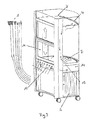
Fig. 3 in einer perspektivischen Ansicht ein drittes Ausführungsbeispiel. - Die in den Zeichnungen dargestellten Ausführungsbeispiele eines mobilen Abzuges umfassen einen Aufbau mit einem Arbeitsraum, der über ein Fenster 11 geöffnet und geschlossen werden kann und dem über eine Medienanschlusseinrichtung 1 verschiedene Medien zuführbar sind.
- Der Abzug ist auf Rollen montiert und damit beweglich.
- Die Medienanschlusseinrichtung 1 besteht wenigstens aus einem kompletten bei Standardabzügen üblichen Satz von Medienanschlüssen u. a. für Brenngas, (Propan oder Edelgas), Wasser, Abwasser, und elektrischer Energie. Weiterhin ist ein Abluftanschluss vorgesehen.
- Das Fenster 11 zum Öffnen und Schließen des Arbeitsraumes ist als zweiteiliges Schiebefenster ausgebildet, das gegenläufig in Pfeilrichtung geöffnet wird, wobei die Ausbildung derart ist, dass der untere Schiebefensterteil beim Öffnen soweit nach unten versenkt wird, dass dadurch die an der Frontblende 12 angeordneten Einrichtungen zum Betätigen der Medien insbesondere die Ventile überdeckt sind, so dass bei geöffnetem Schiebefenster die Betätigung der Medienzuführung nicht möglich ist. Hierdurch ergibt sich eine hohe passive Sicherheit für den Betreiber, da der Benutzer gezwungen ist, den Abzug zu schließen, um mit den Arbeitsvorgängen beispielsweise den Versuchen im Arbeitsraum zu beginnen und die Medien freizugeben.
- Das Abzugsgehäuse ist im unteren Teil beispielsweise bis auf eine Höhe von 900 mm aus Holz-, Kunststoff- und Metallwerkstoffen gebildet. Am oberen Bereich, das heißt beispielsweise ab einer Höhe von 900 mm bis zur Oberkante des Abzuges ist seitlich und hinten ein Einscheibensicherheitsglas vorgesehen, das beispielsweise 6 mm dick ist. Die Front, die das zweiteilige gegenläufige Schiebefenster 11 aufweist ist ebenfalls mit Einscheibensicherheitsglas verglast. Der untere Teil des Schiebefensters 11 ist mit Querschiebern versehen, so dass der Arbeitsraum auch im geschlossenen Zustand des Schiebefensters 11 über die Querschieber zugänglich ist.
- Am unteren Teil des Abzuges befindet sich ein Stauraum, der rechts und links über Querrollläden 3 zugänglich ist.
- Das Abzuggehäuse ist mittels eines Klebers komplett verklebt und bezüglich bestimmter tragender Bauteile kraftschlüssig verbunden.
- Die am Abzug vorgesehenen Rollen sind teilweise feststellbar.
- Die Medienanschlusseinrichtung 1 ist mit flexiblen Schlauchanschlüssen versehen, die aus dem unteren Teil des Abzuges herausführen und im Stauraum untergebracht werden können, wenn sie nicht benötigt werden. Die Anschlüsse können wahlweise links oder rechts aus dem Stauraum herausführen und über entsprechende Kupplungseinrichtungen an den Schlauchanschlüssen mit Versorgungen verbunden werden, die im Raum an beliebiger Stelle vorgesehen sind.
- Abgesehen von den üblichen Standardmedienanschlüssen kann der Abzug mit allen gebräuchlichen Medienanschlüssen ausgestattet sein, die vom Benutzer gefordert werden.
- Wie es weiterhin in
Fig. 1 dargestellt ist, ist die Abluftabsaugung so ausgebildet, dass die Abluft in zwei Teilströmen, nämlich einer Abluftmenge von etwa 30 % direkt über die Tischplatte 7 und etwa 70 % der Abluftmenge unterhalb des Abzugdaches 4 angesaugt und über eine durch eine verglaste, zu Reinigungszwecken abklappbare Prallwand 6 gebildete Druckkammer 5 hinter der Prallwand und vor der Rückwand des Abzugs nach unten in eine unterhalb der Tischplatte 7 liegende Ansaugkammer geführt wird. Von dort erfolgt der Abluftanschluss mittels flexibler Schläuche an die im Raum vorgesehenen Abluftanschlussstutzen. - Zur Unterstützung der Abführung schwerer Gase auf der Tischplatte 7 ist ein Stützventilator 2 vorgesehen, der an der Vorderkante der Arbeitsplatte über das Einströmprofil, das als Hohlprofil ausgebildet ist, einen Zuluftstützstrahl einbringt, der mittels eines Rohrlüfters erzeugt wird.
- Die Anordnung und Ausbildung der Ansaugöffnungen, sowie die oben beschriebene Luftführung bewirken, dass der Abzug mit einer Mindestluftmenge von nur 300 m3/h betreibbar ist, was entsprechende Einsparungen gegenüber üblichen Abzügen bedeutet, die mit einer Mindestluftmenge von ca. 350 bis 400 m3/h arbeiten.
- Bei dem in
Fig. 2 dargestellten Ausführungsbeispiel ist eine abgewandelte Form der Luftabführung vorgesehen, bei der wiederum die Absaugung in zwei Teilströmen über der Tischplatte 7 und unterhalb des Abzugsdaches 4 mit einer Aufteilung der Abluftmenge in etwa 30 % und etwa 70 % jeweils der gesamten Abluftmenge erfolgt. - Die an der Tischplatte 7 angesaugte Abluftmenge wird über eine unterhalb der Tischplatte 7 liegende Druckkammer 14 und von dort über in den Seitenflächen bündig integrierte Luftkanäle 10 in eine zweite oberhalb des Abzugdaches befindliche Druckkammer 8 geführt, in die gleichfalls die direkt unterhalb des Abzugdaches 4 angesaugte Abluftmenge geführt wird. Von der Druckkammer 8 erfolgt der Abluftanschluss mittels flexibler Schläuche 9 wahlweise links oder rechts durch die Abzugseiten an die im Raum vorgesehenen Abluftanschlussstutzen.
- Bei dem in
Fig. 3 dargestellten Ausführungsbeispiel ist die Luftführung umgekehrt, so dass die Abluft, die oberhalb des Abzugdaches 4 angesaugt wird, über die Druckkammer 8 und Luftkanäle 13 nach unten in die Druckkammer 14 geführt wird, in die auch die oberhalb der Tischplatte 7 angesaugte Abluft geführt wird. Die Druckkammer 14 ist über entsprechende Schläuche mit dem Abluftstutzen des Raumes verbindbar. - Den oben beschriebenen Ausführungsbeispielen des erfindungsgemäßen Abzuges ist es gleichfalls gemeinsam, dass innenliegende und von außen abschaltbare Steckdosen vorgesehen sind und dass die Ablufteinschaltung über im Abzugspfosten eingebaute Funktionsanzeigen mit Ablufteinschaltung mittels Funkübertragung zur Schnittstelle im Elektrounterverteiler im Unterrichts- oder Laborraum erfolgt.
Claims (11)
- Mobiler Abzug, der sämtliche Erfordernisse der DIN 12924, Teil 1 erfüllt, mit einem allseitig umschlossenen Arbeitsraum, einer Medienanschlusseinrichtung (1), die einen je nach Bedarf des Benutzers kompletten Satz von Medienanschlüssen umfasst, zur Medienzu- und - abführung zu und aus dem Arbeitsraum und einer Abluftanschlusseinrichtung (2, 4, 5, 6, 9, 10, 14), wobei- der Abzug bodenseitig mit Rollen versehen ist, und- die Medienanschlusseinrichtung (1) sowie die Abluftanschlusseinrichtung (2, 4, 5, 6, 9, 10, 14) mit flexiblen Anschlussleitungen und Kupplungen zum Anschluss an entsprechende stationäre Einrichtungen versehen sind und zumindest die Medienanschlussleitungen (1) von unterhalb des Arbeitsraumes aus dem Abzug herausführen.
- Abzug nach Anspruch 1, wobei die Medienanschlussleitungen (1) wahlweise auf der rechten oder der linken Seite des Abzuges herausführen.
- Abzug nach Anspruch 1 oder 2, wobei die Anschlussleitungen in Stauräumen am unteren Teil des Abzuges unterbringbar sind, die mit Rollläden (3) geöffnet und geschlossen werden können.
- Abzug nach einem der vorhergehenden Ansprüche, wobei an einer Vorderkante einer im Arbeitsraum angeordneten Arbeitsplatte (7) ein Hohlprofil vorgesehen ist, durch das ein Zuluftstützstrahl in den Arbeitsraum zur Abführung schwerer Gase aus dem Arbeitsraum eingebracht werden kann.
- Abzug nach einem der vorhergehenden Ansprüche, wobei die Abluftanschlusseinrichtung (2, 4, 5, 6, 9, 10, 14) derart ausgebildet ist, dass der Abzug mit einer Mindestabluftmenge von 300m3/h betreibbar ist.
- Abzug nach einem der vorhergehenden Ansprüche, wobei die Abluftanschlusseinrichtung (2, 4, 5, 6, 9, 10, 14) derart ausgebildet ist, dass die Abluft durch einen ersten und einen zweiten Teilstrom aus dem Arbeitsraum abgeführt wird.
- Abzug nach Anspruch 6, wobei der erste Teilstrom etwa 30 % der Abluftmenge über der Arbeitsplatte (7) und der zweite Teilstrom etwa 70 % der Abluftmenge unterhalb des Abzugsdaches (4) aus dem Arbeitsraum abführt.
- Abzug nach einem der vorhergehenden Ansprüche, der für den Abluftbetrieb bestimmt ist.
- Abzug nach einem der vorhergehenden Ansprüche, wobei der Arbeitsraum über ein zweiteiliges Fenster (11) geöffnet werden kann, und wobei die beiden Teile des Fensters (11) gegenläufig in vertikaler Richtung verschiebbar sind.
- Abzug nach Anspruch 9, wobei der untere Teil des Fensters (11) soweit in vertikaler Richtung nach unten verschiebbar ist, dass bei geöffnetem Fenster Einrichtungen zum Betätigen der Medienzufuhr in den Arbeitsraum durch den zweiten Teil des Fensters (11) überdeckt sind.
- Abzug nach einem der vorhergehenden Ansprüche, wobei oberhalb eines Abzugsdaches (4) eine Druckkammer (8) angeordnet ist, in die Abluft aus dem Arbeitsraum angesaugt und durch eine im Bereich der Druckkammer (8) angeordnete flexible Abluftleitung für den Anschluss an eine entsprechende stationäre Einrichtung aus dem Abzug abgeführt wird.
Applications Claiming Priority (2)
| Application Number | Priority Date | Filing Date | Title |
|---|---|---|---|
| DE10107371A DE10107371A1 (de) | 2001-02-16 | 2001-02-16 | Mobiler Abzug |
| EP02001935A EP1232805B1 (de) | 2001-02-16 | 2002-01-31 | Mobiler Abzug |
Related Parent Applications (2)
| Application Number | Title | Priority Date | Filing Date |
|---|---|---|---|
| EP02001935.2 Division | 2002-01-31 | ||
| EP02001935A Division EP1232805B1 (de) | 2001-02-16 | 2002-01-31 | Mobiler Abzug |
Publications (3)
| Publication Number | Publication Date |
|---|---|
| EP2055398A2 true EP2055398A2 (de) | 2009-05-06 |
| EP2055398A3 EP2055398A3 (de) | 2010-04-07 |
| EP2055398B1 EP2055398B1 (de) | 2014-08-06 |
Family
ID=7674334
Family Applications (2)
| Application Number | Title | Priority Date | Filing Date |
|---|---|---|---|
| EP02001935A Expired - Lifetime EP1232805B1 (de) | 2001-02-16 | 2002-01-31 | Mobiler Abzug |
| EP09151454.7A Expired - Lifetime EP2055398B1 (de) | 2001-02-16 | 2002-01-31 | Mobiler Abzug |
Family Applications Before (1)
| Application Number | Title | Priority Date | Filing Date |
|---|---|---|---|
| EP02001935A Expired - Lifetime EP1232805B1 (de) | 2001-02-16 | 2002-01-31 | Mobiler Abzug |
Country Status (7)
| Country | Link |
|---|---|
| EP (2) | EP1232805B1 (de) |
| AT (1) | ATE432129T1 (de) |
| CY (1) | CY1109147T1 (de) |
| DE (2) | DE10107371A1 (de) |
| DK (2) | DK1232805T3 (de) |
| ES (2) | ES2509885T3 (de) |
| PT (2) | PT1232805E (de) |
Families Citing this family (3)
| Publication number | Priority date | Publication date | Assignee | Title |
|---|---|---|---|---|
| DE20202026U1 (de) * | 2002-02-11 | 2003-06-26 | Tillmanns, Kurt, 56072 Koblenz | Vorrichtung zur Reduzierung der Luftkontamination |
| DE202004001673U1 (de) | 2004-02-04 | 2004-04-15 | Waldner Labor- Und Schuleinrichtungen Gmbh | Laborarbeitstisch |
| DE102010051364A1 (de) * | 2010-11-13 | 2012-05-16 | Waldner Laboreinrichtungen Gmbh & Co. Kg | Abzugvorrichtung |
Family Cites Families (13)
| Publication number | Priority date | Publication date | Assignee | Title |
|---|---|---|---|---|
| BE623193A (de) * | ||||
| US3041957A (en) | 1959-08-14 | 1962-07-03 | Lab Furniture Company Inc | Mobile laboratory |
| DE2155298C3 (de) | 1971-11-06 | 1975-09-04 | Meteor-Siegen Apparatebau Paul Schmeck Gmbh, 5900 Siegen | Fahrbarer Experimentiertisch für Unterrichtszwecke o.dgl |
| JPS4955560A (de) * | 1972-10-02 | 1974-05-29 | ||
| US3747505A (en) * | 1972-02-18 | 1973-07-24 | American Hospital Supply Corp | Air flow system for fume hood |
| NL7512693A (en) * | 1975-10-30 | 1977-05-03 | Schaik & Berghuis | Fume cupboard made and supplied in two sections - one carrying the service connections for easy access and alteration |
| US4345615A (en) * | 1980-03-13 | 1982-08-24 | Kay Plastic Products, Inc. | Multiphase modular chemical processing station |
| DE8509333U1 (de) | 1985-03-28 | 1985-08-22 | Drake, Francois Prosper Fernand John, London | Laboratoriums-Abzugsschrank |
| DK158776C (da) * | 1985-05-28 | 1990-12-24 | Joergen Aakjaer | Arbejdsskab af stinkskabstypen, med bevaegelig glasforplade |
| DE4040723C2 (de) * | 1990-12-19 | 1996-01-25 | Waldner Laboreinrichtungen | Abrauchabzug |
| GB2294395B (en) | 1994-10-26 | 1998-03-04 | Robert Knight | Ventilated enclosures |
| DE19601468B4 (de) * | 1995-02-09 | 2005-02-10 | Hohenloher Spezialmöbelwerk Schaffitzel GmbH + Co. | Demonstrationsschrank |
| DE29902130U1 (de) * | 1999-02-10 | 1999-04-08 | Würth Elektronik GmbH & Co. KG, 74676 Niedernhall | Einrichtung als Labor mit mindestens einem Laborarbeitsplatz |
-
2001
- 2001-02-16 DE DE10107371A patent/DE10107371A1/de not_active Ceased
-
2002
- 2002-01-31 DK DK02001935T patent/DK1232805T3/da active
- 2002-01-31 DK DK09151454.7T patent/DK2055398T3/da active
- 2002-01-31 PT PT02001935T patent/PT1232805E/pt unknown
- 2002-01-31 ES ES09151454.7T patent/ES2509885T3/es not_active Expired - Lifetime
- 2002-01-31 PT PT91514547T patent/PT2055398E/pt unknown
- 2002-01-31 DE DE50213569T patent/DE50213569D1/de not_active Expired - Lifetime
- 2002-01-31 ES ES02001935T patent/ES2323764T3/es not_active Expired - Lifetime
- 2002-01-31 EP EP02001935A patent/EP1232805B1/de not_active Expired - Lifetime
- 2002-01-31 AT AT02001935T patent/ATE432129T1/de active
- 2002-01-31 EP EP09151454.7A patent/EP2055398B1/de not_active Expired - Lifetime
-
2009
- 2009-06-12 CY CY20091100630T patent/CY1109147T1/el unknown
Also Published As
| Publication number | Publication date |
|---|---|
| PT2055398E (pt) | 2014-10-22 |
| DK2055398T3 (da) | 2014-11-03 |
| EP2055398A3 (de) | 2010-04-07 |
| DK1232805T3 (da) | 2009-08-31 |
| ES2509885T3 (es) | 2014-10-20 |
| EP1232805B1 (de) | 2009-05-27 |
| EP2055398B1 (de) | 2014-08-06 |
| DE10107371A1 (de) | 2002-09-05 |
| EP1232805A3 (de) | 2004-02-04 |
| CY1109147T1 (el) | 2014-07-02 |
| ATE432129T1 (de) | 2009-06-15 |
| DE50213569D1 (de) | 2009-07-09 |
| EP1232805A2 (de) | 2002-08-21 |
| ES2323764T3 (es) | 2009-07-24 |
| PT1232805E (pt) | 2009-06-04 |
Similar Documents
| Publication | Publication Date | Title |
|---|---|---|
| DE69631631T2 (de) | Tragbares Belüftungssystem | |
| WO2007134829A1 (de) | Einrichtung für dunstabzugshauben | |
| EP1832818B1 (de) | Lüftungsanlage | |
| CH704075A1 (de) | Türelement zum Öffnen und/oder Verschliessen eines Raumes mit einer Überströmfunktion. | |
| EP2055398B1 (de) | Mobiler Abzug | |
| EP0337469B2 (de) | Reinraumlaborabzug | |
| EP3102346B1 (de) | Modulare abzugsvorrichtung | |
| DE102008028613A1 (de) | T-förmiges Abzweigstück, insbesondere für ein Lüftungssystem | |
| EP2145134A1 (de) | Dunstabzugsvorrichtung | |
| DE20106395U1 (de) | Mobiler Abzug | |
| EP0687512A2 (de) | Sicherheitslaborabzugschrank | |
| DE4004723C1 (en) | Double-sided fume cupboard - has box-shaped housing with two internal exhaust ducts, etc. | |
| DE10255172A1 (de) | Raumlüftungsgerät | |
| DE60101825T2 (de) | Motorisierte Abzugshaube für Küchen | |
| DE1454629A1 (de) | Klimaanlage mit luftgekuehltem Klimageraet | |
| EP0665380B1 (de) | Montageblock zur Anbringung von bau- und haustechnischen Einrichtungen und/oder Anlagen | |
| DE9317218U1 (de) | Labormöbel | |
| DE7807204U1 (de) | Anschlussvorrichtung fuer die ableitung von kuechenabluft | |
| DE102006013244B4 (de) | Abzug mit Medienmodul | |
| DE102012107249A1 (de) | Container mit Einrichtungen zur Zubereitung von Speisen | |
| DE202020105817U1 (de) | Vorrichtung zum Lüften von Räumen | |
| DE102018220681A1 (de) | Dunstabzugsvorrichtung und Küchenvorrichtung | |
| DE9001798U1 (de) | Durchreicheabzug | |
| EP4719682A1 (de) | Laborabzug mit rahmenprofil im frontschieber | |
| DE1498572C (de) | Installationszelle fur Laboratorien |
Legal Events
| Date | Code | Title | Description |
|---|---|---|---|
| PUAI | Public reference made under article 153(3) epc to a published international application that has entered the european phase |
Free format text: ORIGINAL CODE: 0009012 |
|
| AC | Divisional application: reference to earlier application |
Ref document number: 1232805 Country of ref document: EP Kind code of ref document: P |
|
| AK | Designated contracting states |
Kind code of ref document: A2 Designated state(s): AT BE CH CY DE DK ES FI FR GB GR IE IT LI LU MC NL PT SE TR |
|
| RIC1 | Information provided on ipc code assigned before grant |
Ipc: B01L 9/02 20060101ALI20090404BHEP Ipc: B08B 15/02 20060101AFI20090402BHEP |
|
| RTI1 | Title (correction) |
Free format text: MOBILE FUME HOOD |
|
| PUAL | Search report despatched |
Free format text: ORIGINAL CODE: 0009013 |
|
| AK | Designated contracting states |
Kind code of ref document: A3 Designated state(s): AT BE CH CY DE DK ES FI FR GB GR IE IT LI LU MC NL PT SE TR |
|
| 17P | Request for examination filed |
Effective date: 20100825 |
|
| AKX | Designation fees paid |
Designated state(s): AT BE CH CY DE DK ES FI FR GB GR IE IT LI LU MC NL PT SE TR |
|
| 17Q | First examination report despatched |
Effective date: 20121129 |
|
| GRAP | Despatch of communication of intention to grant a patent |
Free format text: ORIGINAL CODE: EPIDOSNIGR1 |
|
| R17C | First examination report despatched (corrected) |
Effective date: 20121129 |
|
| INTG | Intention to grant announced |
Effective date: 20131107 |
|
| GRAP | Despatch of communication of intention to grant a patent |
Free format text: ORIGINAL CODE: EPIDOSNIGR1 |
|
| INTG | Intention to grant announced |
Effective date: 20140226 |
|
| GRAS | Grant fee paid |
Free format text: ORIGINAL CODE: EPIDOSNIGR3 |
|
| GRAA | (expected) grant |
Free format text: ORIGINAL CODE: 0009210 |
|
| AC | Divisional application: reference to earlier application |
Ref document number: 1232805 Country of ref document: EP Kind code of ref document: P |
|
| AK | Designated contracting states |
Kind code of ref document: B1 Designated state(s): AT BE CH CY DE DK ES FI FR GB GR IE IT LI LU MC NL PT SE TR |
|
| REG | Reference to a national code |
Ref country code: GB Ref legal event code: FG4D Free format text: NOT ENGLISH |
|
| REG | Reference to a national code |
Ref country code: AT Ref legal event code: REF Ref document number: 680757 Country of ref document: AT Kind code of ref document: T Effective date: 20140815 Ref country code: CH Ref legal event code: EP |
|
| REG | Reference to a national code |
Ref country code: CH Ref legal event code: NV Representative=s name: FELBER AND PARTNER AG PATENTANWAELTE, CH |
|
| REG | Reference to a national code |
Ref country code: SE Ref legal event code: TRGR |
|
| REG | Reference to a national code |
Ref country code: IE Ref legal event code: FG4D Free format text: LANGUAGE OF EP DOCUMENT: GERMAN |
|
| REG | Reference to a national code |
Ref country code: DE Ref legal event code: R096 Ref document number: 50215962 Country of ref document: DE Effective date: 20140918 |
|
| REG | Reference to a national code |
Ref country code: ES Ref legal event code: FG2A Ref document number: 2509885 Country of ref document: ES Kind code of ref document: T3 Effective date: 20141020 |
|
| REG | Reference to a national code |
Ref country code: PT Ref legal event code: SC4A Free format text: AVAILABILITY OF NATIONAL TRANSLATION Effective date: 20141013 |
|
| REG | Reference to a national code |
Ref country code: DK Ref legal event code: T3 Effective date: 20141030 |
|
| REG | Reference to a national code |
Ref country code: NL Ref legal event code: T3 |
|
| REG | Reference to a national code |
Ref country code: GR Ref legal event code: EP Ref document number: 20140402142 Country of ref document: GR Effective date: 20141121 |
|
| PG25 | Lapsed in a contracting state [announced via postgrant information from national office to epo] |
Ref country code: CY Free format text: LAPSE BECAUSE OF FAILURE TO SUBMIT A TRANSLATION OF THE DESCRIPTION OR TO PAY THE FEE WITHIN THE PRESCRIBED TIME-LIMIT Effective date: 20140806 |
|
| REG | Reference to a national code |
Ref country code: DE Ref legal event code: R097 Ref document number: 50215962 Country of ref document: DE |
|
| PLBE | No opposition filed within time limit |
Free format text: ORIGINAL CODE: 0009261 |
|
| STAA | Information on the status of an ep patent application or granted ep patent |
Free format text: STATUS: NO OPPOSITION FILED WITHIN TIME LIMIT |
|
| 26N | No opposition filed |
Effective date: 20150507 |
|
| PG25 | Lapsed in a contracting state [announced via postgrant information from national office to epo] |
Ref country code: MC Free format text: LAPSE BECAUSE OF FAILURE TO SUBMIT A TRANSLATION OF THE DESCRIPTION OR TO PAY THE FEE WITHIN THE PRESCRIBED TIME-LIMIT Effective date: 20140806 |
|
| REG | Reference to a national code |
Ref country code: FR Ref legal event code: PLFP Year of fee payment: 15 |
|
| REG | Reference to a national code |
Ref country code: FR Ref legal event code: PLFP Year of fee payment: 16 |
|
| REG | Reference to a national code |
Ref country code: CH Ref legal event code: PCAR Free format text: NEW ADDRESS: DUFOURSTRASSE 116, 8008 ZUERICH (CH) |
|
| PGFP | Annual fee paid to national office [announced via postgrant information from national office to epo] |
Ref country code: GR Payment date: 20170116 Year of fee payment: 16 Ref country code: SE Payment date: 20170119 Year of fee payment: 16 |
|
| PGFP | Annual fee paid to national office [announced via postgrant information from national office to epo] |
Ref country code: PT Payment date: 20170124 Year of fee payment: 16 Ref country code: IE Payment date: 20170123 Year of fee payment: 16 |
|
| PGFP | Annual fee paid to national office [announced via postgrant information from national office to epo] |
Ref country code: TR Payment date: 20170118 Year of fee payment: 16 Ref country code: IT Payment date: 20170124 Year of fee payment: 16 |
|
| REG | Reference to a national code |
Ref country code: FR Ref legal event code: PLFP Year of fee payment: 17 |
|
| REG | Reference to a national code |
Ref country code: SE Ref legal event code: EUG |
|
| PG25 | Lapsed in a contracting state [announced via postgrant information from national office to epo] |
Ref country code: PT Free format text: LAPSE BECAUSE OF NON-PAYMENT OF DUE FEES Effective date: 20180731 Ref country code: SE Free format text: LAPSE BECAUSE OF NON-PAYMENT OF DUE FEES Effective date: 20180201 |
|
| REG | Reference to a national code |
Ref country code: IE Ref legal event code: MM4A |
|
| PG25 | Lapsed in a contracting state [announced via postgrant information from national office to epo] |
Ref country code: GR Free format text: LAPSE BECAUSE OF NON-PAYMENT OF DUE FEES Effective date: 20180802 |
|
| PG25 | Lapsed in a contracting state [announced via postgrant information from national office to epo] |
Ref country code: IE Free format text: LAPSE BECAUSE OF NON-PAYMENT OF DUE FEES Effective date: 20180131 |
|
| PG25 | Lapsed in a contracting state [announced via postgrant information from national office to epo] |
Ref country code: IT Free format text: LAPSE BECAUSE OF NON-PAYMENT OF DUE FEES Effective date: 20180131 |
|
| PGFP | Annual fee paid to national office [announced via postgrant information from national office to epo] |
Ref country code: LU Payment date: 20190122 Year of fee payment: 18 |
|
| PGFP | Annual fee paid to national office [announced via postgrant information from national office to epo] |
Ref country code: NL Payment date: 20190122 Year of fee payment: 18 Ref country code: FI Payment date: 20190118 Year of fee payment: 18 Ref country code: ES Payment date: 20190215 Year of fee payment: 18 Ref country code: FR Payment date: 20190123 Year of fee payment: 18 Ref country code: CH Payment date: 20190124 Year of fee payment: 18 |
|
| PGFP | Annual fee paid to national office [announced via postgrant information from national office to epo] |
Ref country code: DK Payment date: 20190124 Year of fee payment: 18 Ref country code: AT Payment date: 20190118 Year of fee payment: 18 Ref country code: BE Payment date: 20190122 Year of fee payment: 18 |
|
| REG | Reference to a national code |
Ref country code: FI Ref legal event code: MAE |
|
| REG | Reference to a national code |
Ref country code: DK Ref legal event code: EBP Effective date: 20200131 Ref country code: CH Ref legal event code: PL |
|
| REG | Reference to a national code |
Ref country code: NL Ref legal event code: MM Effective date: 20200201 |
|
| REG | Reference to a national code |
Ref country code: AT Ref legal event code: MM01 Ref document number: 680757 Country of ref document: AT Kind code of ref document: T Effective date: 20200131 |
|
| GBPC | Gb: european patent ceased through non-payment of renewal fee |
Effective date: 20200131 |
|
| REG | Reference to a national code |
Ref country code: BE Ref legal event code: MM Effective date: 20200131 |
|
| PG25 | Lapsed in a contracting state [announced via postgrant information from national office to epo] |
Ref country code: GB Free format text: LAPSE BECAUSE OF NON-PAYMENT OF DUE FEES Effective date: 20200131 Ref country code: NL Free format text: LAPSE BECAUSE OF NON-PAYMENT OF DUE FEES Effective date: 20200201 Ref country code: FI Free format text: LAPSE BECAUSE OF NON-PAYMENT OF DUE FEES Effective date: 20200131 Ref country code: FR Free format text: LAPSE BECAUSE OF NON-PAYMENT OF DUE FEES Effective date: 20200131 Ref country code: LU Free format text: LAPSE BECAUSE OF NON-PAYMENT OF DUE FEES Effective date: 20200131 |
|
| PG25 | Lapsed in a contracting state [announced via postgrant information from national office to epo] |
Ref country code: LI Free format text: LAPSE BECAUSE OF NON-PAYMENT OF DUE FEES Effective date: 20200131 Ref country code: CH Free format text: LAPSE BECAUSE OF NON-PAYMENT OF DUE FEES Effective date: 20200131 Ref country code: BE Free format text: LAPSE BECAUSE OF NON-PAYMENT OF DUE FEES Effective date: 20200131 Ref country code: AT Free format text: LAPSE BECAUSE OF NON-PAYMENT OF DUE FEES Effective date: 20200131 |
|
| PG25 | Lapsed in a contracting state [announced via postgrant information from national office to epo] |
Ref country code: DK Free format text: LAPSE BECAUSE OF NON-PAYMENT OF DUE FEES Effective date: 20200131 |
|
| PGFP | Annual fee paid to national office [announced via postgrant information from national office to epo] |
Ref country code: DE Payment date: 20210129 Year of fee payment: 20 |
|
| REG | Reference to a national code |
Ref country code: ES Ref legal event code: FD2A Effective date: 20210607 |
|
| PG25 | Lapsed in a contracting state [announced via postgrant information from national office to epo] |
Ref country code: ES Free format text: LAPSE BECAUSE OF NON-PAYMENT OF DUE FEES Effective date: 20200201 |
|
| REG | Reference to a national code |
Ref country code: DE Ref legal event code: R071 Ref document number: 50215962 Country of ref document: DE |
|
| PG25 | Lapsed in a contracting state [announced via postgrant information from national office to epo] |
Ref country code: TR Free format text: LAPSE BECAUSE OF NON-PAYMENT OF DUE FEES Effective date: 20180131 |