EP2055482A2 - Verfahren zur bestimmung von gedruckten bildern - Google Patents
Verfahren zur bestimmung von gedruckten bildern Download PDFInfo
- Publication number
- EP2055482A2 EP2055482A2 EP07788596A EP07788596A EP2055482A2 EP 2055482 A2 EP2055482 A2 EP 2055482A2 EP 07788596 A EP07788596 A EP 07788596A EP 07788596 A EP07788596 A EP 07788596A EP 2055482 A2 EP2055482 A2 EP 2055482A2
- Authority
- EP
- European Patent Office
- Prior art keywords
- printing
- printed
- characteristic images
- register
- marks
- Prior art date
- Legal status (The legal status is an assumption and is not a legal conclusion. Google has not performed a legal analysis and makes no representation as to the accuracy of the status listed.)
- Granted
Links
Images
Classifications
-
- B—PERFORMING OPERATIONS; TRANSPORTING
- B41—PRINTING; LINING MACHINES; TYPEWRITERS; STAMPS
- B41F—PRINTING MACHINES OR PRESSES
- B41F33/00—Indicating, counting, warning, control or safety devices
- B41F33/0081—Devices for scanning register marks
-
- B—PERFORMING OPERATIONS; TRANSPORTING
- B41—PRINTING; LINING MACHINES; TYPEWRITERS; STAMPS
- B41F—PRINTING MACHINES OR PRESSES
- B41F33/00—Indicating, counting, warning, control or safety devices
-
- B—PERFORMING OPERATIONS; TRANSPORTING
- B41—PRINTING; LINING MACHINES; TYPEWRITERS; STAMPS
- B41F—PRINTING MACHINES OR PRESSES
- B41F13/00—Common details of rotary presses or machines
- B41F13/08—Cylinders
- B41F13/10—Forme cylinders
- B41F13/12—Registering devices
- B41F13/14—Registering devices with means for displacing the cylinders
-
- B—PERFORMING OPERATIONS; TRANSPORTING
- B41—PRINTING; LINING MACHINES; TYPEWRITERS; STAMPS
- B41P—INDEXING SCHEME RELATING TO PRINTING, LINING MACHINES, TYPEWRITERS, AND TO STAMPS
- B41P2213/00—Arrangements for actuating or driving printing presses; Auxiliary devices or processes
- B41P2213/90—Register control
-
- B—PERFORMING OPERATIONS; TRANSPORTING
- B41—PRINTING; LINING MACHINES; TYPEWRITERS; STAMPS
- B41P—INDEXING SCHEME RELATING TO PRINTING, LINING MACHINES, TYPEWRITERS, AND TO STAMPS
- B41P2233/00—Arrangements for the operation of printing presses
- B41P2233/50—Marks on printed material
- B41P2233/52—Marks on printed material for registering
Definitions
- the present invention generally relates to a method of determining printed images, particularly applicable to a printer with printing groups each carrying a printing roller with a respective characteristic image to be printed on a material, but the determination or discernment of which is not initially possible, either because its belonging to a certain roller is in principle unknown or because some of the characteristic images would appear partly or completely superposed in the event of performing a first printing.
- printers such as flexographic printers comprising a series of printing groups, with printing rollers, with characteristic images or marks to be printed incorporated in the rollers either directly, for example by intaglio printing, or by means of corresponding printing plates or engraved jacket in the case of flexography.
- Said printing machines can incorporate automatic systems for adjusting the register of the printing or of the transfer of the ink through inspection of the characteristic images or marks printed on a material.
- the method proposed by the present invention is applicable for the mentioned case that the order of the marks is not always fixed with respect to the order of the printing groups.
- Such objective is achieved with the present invention by means of providing a method the application of which allows clearly determining the different printed marks to perform subsequent operations, as well as determining which mark corresponds to each printing group, without needing to visually inspect the roller, jacket, printing plate or printed material, thus reducing the wait time prior to starting the register and pressure adjustment operations necessary to begin printing compared to conventional visual inspection methods described in the previous section.
- the present invention relates to a method of determining printed images, of the type comprising the use of a printer with at least one first and one second printing groups including respective first and second printing rollers, generally with one and the same printing development, each of said printing rollers with at least one respective characteristic image to be printed on a material.
- the proposed method comprises using as characteristic images several images, at least some of which, if printed, would appear partially or completely superposed in relation to one another on an area of said material.
- the proposed method according to the first aspect of the invention comprises performing the following steps:
- step e) comprises performing said operation of associating characteristic images with respect to printing rollers by means of the following sub-steps:
- said characteristic images are mounting marks used for positioning and mounting, or pre-mounting, printing plates on printing rollers, which are common in printing plates found on the market, whereby register marks are not necessary expressly to perform said pressure and register adjustments, since by means of the method proposed by the first aspect of the invention said mounting marks are used to perform their original function, i.e., the correct mounting of the printing plates on the printing rollers, in addition to performing the functions conventionally performed with other additional marks, i.e., the marks referring to the mentioned pressure adjustments and transverse and longitudinal register adjustment.
- the proposed method is applied to the determination of printed images with respect to printing groups, and is of the type comprising:
- the present invention relates to a method of determining printed images, of the type comprising the use of a printer of any type but with at least two printing groups with respective printing rollers (or another class of support which is not necessarily a roller) with respective characteristic images to be printed.
- said characteristic images are auxiliary marks for register M 1 , M 2 , M 3 ...M n located in respective sides of printing plates C 1 , C 2 , C 3 ...C n , for being printed in a side margin of a laminar material 2 to be printed.
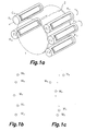
- the method is applied to a flexographic printer of the type comprising a rotating support drum 1 (shown transparently for the sake of visual clarity) on which a laminar material to be printed 2 (shown only in part for the sake of clarity) is supported, with a plurality of printing groups (not all shown) arranged around said support drum 1 and spaced along its perimeter, including respective printing rollers R 1 , R 2 , R 3 ... R n , each of them with at least one respective mark to be printed M 1 , M 2 , M 3 ...M n .
- the method comprises performing all the steps for all the printing groups and all the marks M 1 , M 2 , M 3 ...M n .
- Figures 1 bans 2b show the marks printed by the first printing of step i) of the method proposed by the second aspect of the invention (said figures do not show the laminar material 2 on the they have been printed).
- the mentioned distinguishing characteristic of the marks is the relative position within the printing, there being for said embodiment a series of windows (one per mark) delimiting respective areas where it is possible to detect a mark, each mark being moved, according to the proposed method, only through the inside of its respective window, without the possibility of entering in the window of another mark.
- the marks for example the marks shown in Figures 1b and 1c M 1 , M 2 , M 3 , M 4 , M 5 , are of the same color, the fact that each of them can be moved only through the inside of its respective window (not shown) allows distinguishing them by their relative position, despite the fact that all of them are identical and the same color.
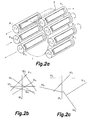
- marks M 1 , M 2 , M 3 , M 4 , M 5 , M 6 , M 7 shown in Figures 2a to 2c are respective segments of lines, each of them with a different inclination, and which unlike the marks of Figures 1a to 1c , have been printed substantially on one and the same marginal area of the laminar material 2, without being longitudinally separated along the laminar material 2 by more than the small (longitudinal and transverse) separations typical of register errors (which can be seen in Figure 2b ), or the separations forced in step iii) of the proposed method which can be seen in Figure 2c (as also occurs with the embodiment of Figure 1c ).
- the marks M 1 , M 2 , M 3 ...M n are different geometric figures.
- the method proposed by the second aspect of the invention comprises performing previously described step ii) for detecting the marks as they are depicted in Figures 1b and 2b .
- an automatic detection system which, for the embodiment shown in Figures 2b and 2c , comprises, for the purpose of performing the detections visually, an automatic image capture and treatment system (not shown) formed, for example, by at least one camera located above the rotating support drum 1, upstream with respect to the direction of movement of the laminar material 2, associated to a corresponding electronic circuitry, directly on the printed laminar material 2 or in a corresponding monitor or display (not shown), said automatic image capture and treatment system being associated to a corresponding electronic system suitable for performing at least said steps vi) to ix), as well as collaborating, if necessary, when performing steps ii) and v), as well as giving the orders by means of the corresponding sending of suitable control signals to means of actuating the groups and the printing rollers, which allow performing steps i), iii) and iv).
- the mentioned automatic detection system comprises one or more photoelectric sensors, also associated to an electronic system like that described in the preceding paragraph.
- said step comprises moving the transverse and/or longitudinal register of at least all except one of said printing rollers R 1 , R 2 , R 3 ... R n , each in a different direction or in the same direction as another but with a different magnitude different, or withdrawing same from printing status.
- step iii) is performed for moving the printing rollers R 1 , R 2 , R 3 , R 4 , R 5 shown therein according to the indicative arrows also shown therein, i.e.:
- Said Figure 1c shows the previous positions of the marks (i.e., those shown in Figure 1a ) by means of a number of corresponding "x", which allows performing a comparison with their respective current positions, which allows appreciating how all the marks, except that indicated as M 3 , have undergone respective positional discrepancies, determined in step vi) of the method, and different from one another, specifically mark M 5 has been moved to the right mark M 4 to the left, mark M 2 upwards and mark M 1 downwards.
- said step vi) has been performed to determine a series of positional discrepancies different for all except one of the marks, i.e., for M 1 , M 2 , M 4 and M 5 .
- the method proposed by the second aspect of the invention comprises performing said step vii) to determine that each of the printing rollers R 1 , R 2 , R 4 and R 5 actuated in step iii) is associated to one of said marks M 1 , M 2 , M 4 and M 5 which have undergone respective positional discrepancies, if the transverse and/or longitudinal register of said printing roller R 1 , R 2 , R 4 and R 5 has been moved in said step iii), with a direction corresponding to that experienced by the printed mark M 2 , M 3 , M 4 and M 5 , i.e., mark M 2 corresponds to roller R 2 , M 3 to R 3 , M 4 to R 4 and M 5 to R 5 .
- the method comprises determining in step viii) that the third roller R 3 , the register of which has not been moved, is associated to mark M 3 which has not undergone any positional discrepancy.
- step iii) The movements to which the registers of the printing rollers have been subjected in step iii) are enough for the embodiment shown in Figures 1a to 1c , but this is not the case for one embodiment which involves using a machine with a larger number of printing rollers, as is the case shown in Figure 2a .
- step iii) is performed for moving the printing rollers R 1 , R 2 , R 3 , R 4 , R 5 , R 6 , R 7 , shown therein according to the indicative arrows also shown therein, i.e.:
- the fourth printing roller R 4 is not actuated in said step iii), therefore it is not moved in any direction.
- Said Figure 2c also shows how all the marks, except those indicated as M 4 and as M 1 , have undergone respective positional discrepancies, determined in step vi) of the method, and different from one another, specifically mark M 5 has been moved to the right, mark M 6 to the left, mark M 3 upwards, mark M 2 downwards and mark M 7 also to the right but with a smaller magnitude than M 5 .
- said step vi) has been performed to determine a series of positional discrepancies different for all except two of the marks, i.e., for M 2 , M 3 , M 5 , M 6 and M 7 .
- Figure 2c also shows that mark M 1 has not been printed, which has been determined in step vi) as a disappearance of said mark M 1 .
- the method proposed by the second aspect of the invention comprises performing said step vii) to determine that each of the printing rollers R 2 , R 3 , R 5 , R 6 and R 7 actuated in step iii) is associated to one of said marks M 2 , M 3 , M 5 , M 6 and M 7 which have undergone respective positional discrepancies, if the transverse and/or longitudinal register of said printing roller R 2 , R 3 , R 5 , R 6 and R 7 has been moved in said step iii), with a direction and a magnitude corresponding to that experienced by the printed mark M 2 , M 3 , M 5 , M 6 and M 7 , i.e., mark M 2 corresponds to roller R 2 , M 3 to R 3 , M 5 to R 5 , M 6 to R 6 , and M 7 to R 7 .
- said magnitudes have pre-determined values.
- the method proposed by the second aspect of the invention comprises determining in step viii) that the fourth roller R 4 , which has not been moved, is associated to the mark M 4 which has not undergone any positional discrepancy, as well as performing said step ix) to determine that the first printing roller R 1 withdrawn from the printing upon being actuated in said step iii) is associated to the first mark M 1 , which has disappeared from the printing.
- the proposed method is performed before a process of register adjustment of said printing rollers R 1 , R 2 , R 3 ... R n .
- the method proposed by the second aspect of the invention is performed before a process of pressure adjustment of at least part of the rollers of said printing groups.
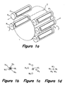
- Figure 3b shows a hypothetical preliminary printing, for the purpose of clarifying the explanation of the method proposed by the first aspect of the invention, since it is not essential to perform printing of the marks M 1 , M 2 , M 3 , M 4 , M 5 before step a).
- Said circles are an exaggerated representation of the real marks, for the sake of clarity, since they are actually microdots generally having a diameter of substantially 0.1 mm to 1 mm or slightly greater.
- said marks M 1 , M 2 , M 3 , M 4 , M 5 are auxiliary mounting marks used for positioning and coupling said printing plates C 1 , C 2 , C 3 , C 4 C 5 on said printing rollers R 1 , R 2 , R 3 , R 4 ,R 5 .
- Figure 3b shows the marks M 1 , M 2 , M 3 , M 4 , M 5 as they would appear printed if a printing before step a) of the method proposed by the first aspect of the invention, for the embodiment in which they are the mentioned microdots, were performed. It can be seen in said Figure 3b that the microdots M 1 , M 2 , M 3 , M 4 , M 5 appear partially superposed, a register adjustment of the printing rollers R 1 , R 2 , R 3 , R 4 , R 5 not having been yet performed.
- Said superposition although partial, initially prevents the determination or discernment of each mark, it not being possible to clearly distinguish each mark separately, which makes it difficult, and even in some cases impossible, to determine which roller each mark belongs to, as well as their pressure adjustment, since the marks are not seen in their entirety, and their register adjustment, since it is not possible to identify which roller each mark belongs to.
- Figure 3c shows the same marks or microdots M 1 , M 2 , M 3 , M 4 , M 5 once they have been printed in step b), step a) for moving the printing rollers R 2 , R 3 , R 4 , R 5 shown in Figure 3a having been moved, for the embodiment shown, according to the indicative arrows also shown therein, i.e.:
- Said Figure 3c depicts the preliminary positions that the marks would have adopted if they had been printed before step a) (i.e., those shown in Figure 3a) by means of corresponding "x", which allows performing a comparison with their respective current positions, which allows appreciating how all the marks, except that indicated as M 1 , have undergone respective positional discrepancies.
- step a it is not necessary to perform printing before step a), i.e., the printing shown by Figure 3b is not performed, therefore the mentioned positional discrepancies are not determined by comparing each printed mark with its preliminary position but rather by means of the previously described step d) consisting of comparing the relative positions detected in step c) with the relative position of said area Z of the material 2, to determine the positional discrepancies for all the marks M 2 , M 3 , M 4 , M 5 except for a first mark indicated as M 1 .
- step d) has been performed to determine a series of different positional discrepancies for all except one of the marks, i.e., for M 2 , M 3 , M 4 and M 5 .
- marks M 1 , M 2 , M 3 , M 4 and M 5 have been separated as seen in Figure 3c, they can be easily distinguished, which makes it possible to perform the operations of determining or associating marks M 1 , M 2 , M 3 , M 4 and M 5 with respect to printing rollers R 1 , R 2 , R 3 , R 4 , R 5 (according to steps e1) to e3) described in a previous section) as well as register adjustment and pressure adjustment of the printing rollers R 1 , R 2 , R 3 , R 4 , R 5 .
- the method proposed by the first aspect of the invention comprises performing said pressure adjustment by means of using an automatic image capture (camera or the like) and treatment system associated to an electronic system for, according to one embodiment, detecting the absence or presence of each of said marks M 1 , M 2 , M 3 , M 4 , M 5 on said laminar material 2 and acting accordingly by increasing or decreasing the pressure exerted by each printing roller R 1 , R 2 , R 3 , R 4 , R 5 on the laminar material 2, as well as the pressure of their associated ink rollers (not shown).
- an automatic image capture camera or the like
- treatment system associated to an electronic system for, according to one embodiment, detecting the absence or presence of each of said marks M 1 , M 2 , M 3 , M 4 , M 5 on said laminar material 2 and acting accordingly by increasing or decreasing the pressure exerted by each printing roller R 1 , R 2 , R 3 , R 4 , R 5 on the laminar material 2, as well as the pressure of their associated ink rollers (
- the method proposed by the first aspect of the invention comprises, to perform said pressure adjustment, comparing, by means of said electronic system, the marks M 1 , M 2 , M 3 , M 4 , M 5 captured with respective pre-determined reference marks registered in said electronic system and indicative of a good printing quality (due to their color, shape, etc.), and if said comparison offers as a result a discrepancy or deviation indicative of the fact that the quality of any of the marks M 1 , M 2 , M 3 , M 4 , M 5 captured is not good, compensating said discrepancy by means of adjusting the pressure of the corresponding printing roller R 1 , R 2 , R 3 , R 4 , R 5 which has printed said image and of a corresponding ink roller (not shown) to which it is associated.
- the method proposed by the first aspect comprises taking as a common reference a first mark M 1 (the printing roller R 1 of which has not been moved in step a)) and adjusting the position of the printing rollers R 2 , R 3 , R 4 , R 5 carrying the remaining marks M 2 , M 3 , M 4 , M 5 until the position of said marks M 2 , M 3 , M 4 , M 5 , once they have been printed on the material 2, is identical to that of said first mark M 1 , i.e., until all the marks M 1 , M 2 , M 3 , M 4 , M 5 overlap as shown in Figure 3d.
- the method proposed by the first aspect of the invention comprises:
- the common reference position is not the position of the first mark M 1 detected in step c), but another different one, such as a pre-determined position different from the relative positions of the marks M 1 , M 2 , M 3 , M 4 , M 5 detected in step c), it being possible for said embodiment, not shown, that the first mark M 1 has also been moved in step a), since it is not used as reference for the register adjustment of the printing rollers R 2 , R 3 , R 4 , R 5 of the remaining marks M 2 , M 3 , M 4 , M 5 .
Landscapes
- Engineering & Computer Science (AREA)
- Mechanical Engineering (AREA)
- Inking, Control Or Cleaning Of Printing Machines (AREA)
- Printing Methods (AREA)
Applications Claiming Priority (2)
| Application Number | Priority Date | Filing Date | Title |
|---|---|---|---|
| ES200602036A ES2300196B1 (es) | 2006-07-28 | 2006-07-28 | Metodo de determinacion de imagenes impresas respecto a grupos de impresion. |
| PCT/ES2007/000348 WO2008012381A2 (es) | 2006-07-28 | 2007-06-12 | Método de determinación de imágenes impresas |
Publications (3)
| Publication Number | Publication Date |
|---|---|
| EP2055482A2 true EP2055482A2 (de) | 2009-05-06 |
| EP2055482A4 EP2055482A4 (de) | 2010-04-14 |
| EP2055482B1 EP2055482B1 (de) | 2018-11-14 |
Family
ID=38981825
Family Applications (1)
| Application Number | Title | Priority Date | Filing Date |
|---|---|---|---|
| EP07788596.0A Active EP2055482B1 (de) | 2006-07-28 | 2007-06-12 | Verfahren zur bestimmung von gedruckten bildern |
Country Status (4)
| Country | Link |
|---|---|
| EP (1) | EP2055482B1 (de) |
| BR (1) | BRPI0714647B1 (de) |
| ES (2) | ES2300196B1 (de) |
| WO (1) | WO2008012381A2 (de) |
Cited By (6)
| Publication number | Priority date | Publication date | Assignee | Title |
|---|---|---|---|---|
| EP2384889A1 (de) * | 2010-05-03 | 2011-11-09 | Advanced Vision Technology (AVT) Ltd. | Verfahren zur Einstellung und Steuerung einer Druckmaschine mittels Minutenmarkierungen |
| ITVI20100163A1 (it) * | 2010-06-11 | 2011-12-12 | Ofem Converting S R L | Procedimento per l'allineamento dei registri del colore per macchine da stampa e relativo programma per elaboratore |
| EP2422979A1 (de) * | 2010-08-31 | 2012-02-29 | Fischer & Krecke GmbH | Drehdruckpresse mit zentralem Druckzylinder |
| EP2743084A4 (de) * | 2011-08-12 | 2015-09-02 | Comexi Group Industries Sau | Verfahren zur überwachung des betriebs einer druckmaschine und flexodruckmaschine zur umsetzung des verfahrens |
| EP3251849A1 (de) * | 2016-05-31 | 2017-12-06 | Windmöller & Hölscher KG | Flexodruckmaschine |
| EP4026697A1 (de) * | 2021-01-08 | 2022-07-13 | manroland Goss web systems GmbH | Druckkontrollstreifen |
Family Cites Families (8)
| Publication number | Priority date | Publication date | Assignee | Title |
|---|---|---|---|---|
| DE3136701C1 (de) * | 1981-09-16 | 1983-04-07 | M.A.N.- Roland Druckmaschinen AG, 6050 Offenbach | Vorrichtung zum Abtasten von auf Druckgut aufgedruckten,die Lagegenauigkeit des Druckfarbenauftrages charakterisierender Passmarken |
| FR2578486B1 (fr) * | 1985-03-08 | 1987-06-12 | Bertin & Cie | Procede et dispositif de positionnement d'objets les uns par rapport aux autres, en particulier des rouleaux d'impression de couleurs dans une presse rotative offset |
| US4887530A (en) * | 1986-04-07 | 1989-12-19 | Quad/Tech, Inc. | Web registration control system |
| DE3809941A1 (de) * | 1987-03-26 | 1988-10-06 | Koenig & Bauer Ag | Verfahren zum positionieren von plattenzylindern in einer mehrfarben-rotationsdruckmaschine |
| DE19614397C2 (de) * | 1996-04-12 | 2001-04-26 | Roland Man Druckmasch | Antrieb mit Registervorrichtung für eine Druckeinheit einer Rollenrotationsdruckmaschine |
| NL1004663C2 (nl) * | 1996-12-02 | 1998-06-03 | Q I Press Controls V O F | Werkwijze en inrichting voor het controleren van drukwerk. |
| US5857784A (en) * | 1997-01-28 | 1999-01-12 | Bayer Corp. Agfa Division | Image position error detection technique |
| ATE394226T1 (de) * | 2003-03-20 | 2008-05-15 | Comexi Sa | Verfahren zum registrieren unterschiedlicher farben in der flexographie und flexographischer drucker umfassend eine vorrichtung zur umsetzung des verfahrens |
-
2006
- 2006-07-28 ES ES200602036A patent/ES2300196B1/es active Active
-
2007
- 2007-06-12 ES ES07788596T patent/ES2712248T3/es active Active
- 2007-06-12 EP EP07788596.0A patent/EP2055482B1/de active Active
- 2007-06-12 WO PCT/ES2007/000348 patent/WO2008012381A2/es not_active Ceased
- 2007-06-12 BR BRPI0714647-7A patent/BRPI0714647B1/pt active IP Right Grant
Cited By (8)
| Publication number | Priority date | Publication date | Assignee | Title |
|---|---|---|---|---|
| EP2384889A1 (de) * | 2010-05-03 | 2011-11-09 | Advanced Vision Technology (AVT) Ltd. | Verfahren zur Einstellung und Steuerung einer Druckmaschine mittels Minutenmarkierungen |
| ITVI20100163A1 (it) * | 2010-06-11 | 2011-12-12 | Ofem Converting S R L | Procedimento per l'allineamento dei registri del colore per macchine da stampa e relativo programma per elaboratore |
| EP2422979A1 (de) * | 2010-08-31 | 2012-02-29 | Fischer & Krecke GmbH | Drehdruckpresse mit zentralem Druckzylinder |
| WO2012028358A1 (en) * | 2010-08-31 | 2012-03-08 | Fischer & Krecke Gmbh | Rotary printing press with central impression cylinder |
| EP2743084A4 (de) * | 2011-08-12 | 2015-09-02 | Comexi Group Industries Sau | Verfahren zur überwachung des betriebs einer druckmaschine und flexodruckmaschine zur umsetzung des verfahrens |
| EP3251849A1 (de) * | 2016-05-31 | 2017-12-06 | Windmöller & Hölscher KG | Flexodruckmaschine |
| WO2017207670A1 (de) * | 2016-05-31 | 2017-12-07 | Windmöller & Hölscher Kg | Flexodruckmaschine |
| EP4026697A1 (de) * | 2021-01-08 | 2022-07-13 | manroland Goss web systems GmbH | Druckkontrollstreifen |
Also Published As
| Publication number | Publication date |
|---|---|
| ES2300196A1 (es) | 2008-06-01 |
| WO2008012381A2 (es) | 2008-01-31 |
| ES2712248T3 (es) | 2019-05-10 |
| BRPI0714647B1 (pt) | 2018-07-31 |
| WO2008012381B1 (es) | 2008-04-17 |
| ES2300196B1 (es) | 2009-02-01 |
| EP2055482B1 (de) | 2018-11-14 |
| BRPI0714647A2 (pt) | 2012-12-25 |
| WO2008012381A3 (es) | 2008-03-06 |
| EP2055482A4 (de) | 2010-04-14 |
Similar Documents
| Publication | Publication Date | Title |
|---|---|---|
| US20060230358A1 (en) | System for inspecting a printed image | |
| EP2055482B1 (de) | Verfahren zur bestimmung von gedruckten bildern | |
| JP6738269B2 (ja) | 画像検査システムをチェックするための方法 | |
| EP2428360B1 (de) | Verfahren und vorrichtung zur montage von druckplatten | |
| JP4714675B2 (ja) | 印刷機において少なくとも1つのレジスタを制御する装置 | |
| US9855738B2 (en) | Method for controlling the operation of a printing press and a flexographic printing press for implementing said method | |
| US8813647B2 (en) | Method and device for determining register deviations through recursion analysis | |
| EP2384889A1 (de) | Verfahren zur Einstellung und Steuerung einer Druckmaschine mittels Minutenmarkierungen | |
| US6553908B1 (en) | Web fanout control system | |
| US7219606B2 (en) | Method and apparatus for measuring, setting and controlling longitudinal and lateral register as well as parallelness of the printing register in a multicolor printing machine | |
| EP2085223A1 (de) | Verfahren zur positionseinstellung von druckerkörpern in flexodruckmaschinen | |
| EP1604820B1 (de) | Verfahren zum registrieren unterschiedlicher farben in der flexographie und flexographischer drucker umfassend eine vorrichtung zur umsetzung des verfahrens | |
| EP1897690B1 (de) | Verfahren zur automatischen einstellung des druckdruckes in flexographischen druckmaschinen | |
| US20040103810A1 (en) | Method of compensating for misregistration during operation of a printing press | |
| JP2003089194A (ja) | 印刷機の刷版の装着・確認装置及びこの装置を用いた印刷機 | |
| US6848361B2 (en) | Control device and method to prevent register errors | |
| US8001900B2 (en) | Home position storage unit and home position storage method for use with printing press | |
| JP2002137529A (ja) | 印刷原画作製時の過剰充填または過少充填を最低限に抑える方法 | |
| JP2800560B2 (ja) | 新聞刷版誤装着検出装置 | |
| JP3622424B2 (ja) | 刷版の識別付与方法,刷版の装着・確認方法およびその装置 | |
| EP1482383A1 (de) | Verfahren und Steuerungseinrichtung zum Vermeiden von Registerfehlern | |
| DE102004036876A1 (de) | Verfahren und Vorrichtung zur Voreinstellung von Registerstelleinrichtungen | |
| JP2836930B2 (ja) | 見当調整方法及び装置 | |
| CN120963191A (zh) | 检测胶版印刷机中基材印张上不希望的油墨施加的方法 | |
| JP2526877B2 (ja) | 多色印刷機用見当制御装置 |
Legal Events
| Date | Code | Title | Description |
|---|---|---|---|
| PUAI | Public reference made under article 153(3) epc to a published international application that has entered the european phase |
Free format text: ORIGINAL CODE: 0009012 |
|
| 17P | Request for examination filed |
Effective date: 20090216 |
|
| AK | Designated contracting states |
Kind code of ref document: A2 Designated state(s): AT BE BG CH CY CZ DE DK EE ES FI FR GB GR HU IE IS IT LI LT LU LV MC MT NL PL PT RO SE SI SK TR |
|
| AX | Request for extension of the european patent |
Extension state: AL BA HR MK RS |
|
| DAX | Request for extension of the european patent (deleted) | ||
| RAP1 | Party data changed (applicant data changed or rights of an application transferred) |
Owner name: COMEXI GROUP INDUSTRIES, S.A. |
|
| A4 | Supplementary search report drawn up and despatched |
Effective date: 20100317 |
|
| RIC1 | Information provided on ipc code assigned before grant |
Ipc: B41F 33/00 20060101AFI20090309BHEP Ipc: B41F 13/14 20060101ALI20100311BHEP |
|
| 17Q | First examination report despatched |
Effective date: 20160627 |
|
| STAA | Information on the status of an ep patent application or granted ep patent |
Free format text: STATUS: EXAMINATION IS IN PROGRESS |
|
| GRAP | Despatch of communication of intention to grant a patent |
Free format text: ORIGINAL CODE: EPIDOSNIGR1 |
|
| STAA | Information on the status of an ep patent application or granted ep patent |
Free format text: STATUS: GRANT OF PATENT IS INTENDED |
|
| INTG | Intention to grant announced |
Effective date: 20180705 |
|
| GRAS | Grant fee paid |
Free format text: ORIGINAL CODE: EPIDOSNIGR3 |
|
| GRAA | (expected) grant |
Free format text: ORIGINAL CODE: 0009210 |
|
| STAA | Information on the status of an ep patent application or granted ep patent |
Free format text: STATUS: THE PATENT HAS BEEN GRANTED |
|
| AK | Designated contracting states |
Kind code of ref document: B1 Designated state(s): AT BE BG CH CY CZ DE DK EE ES FI FR GB GR HU IE IS IT LI LT LU LV MC MT NL PL PT RO SE SI SK TR |
|
| REG | Reference to a national code |
Ref country code: GB Ref legal event code: FG4D |
|
| REG | Reference to a national code |
Ref country code: CH Ref legal event code: EP Ref country code: AT Ref legal event code: REF Ref document number: 1064329 Country of ref document: AT Kind code of ref document: T Effective date: 20181115 |
|
| REG | Reference to a national code |
Ref country code: DE Ref legal event code: R096 Ref document number: 602007056824 Country of ref document: DE |
|
| REG | Reference to a national code |
Ref country code: IE Ref legal event code: FG4D |
|
| REG | Reference to a national code |
Ref country code: NL Ref legal event code: MP Effective date: 20181114 |
|
| REG | Reference to a national code |
Ref country code: LT Ref legal event code: MG4D |
|
| REG | Reference to a national code |
Ref country code: AT Ref legal event code: MK05 Ref document number: 1064329 Country of ref document: AT Kind code of ref document: T Effective date: 20181114 |
|
| PG25 | Lapsed in a contracting state [announced via postgrant information from national office to epo] |
Ref country code: BG Free format text: LAPSE BECAUSE OF FAILURE TO SUBMIT A TRANSLATION OF THE DESCRIPTION OR TO PAY THE FEE WITHIN THE PRESCRIBED TIME-LIMIT Effective date: 20190214 Ref country code: AT Free format text: LAPSE BECAUSE OF FAILURE TO SUBMIT A TRANSLATION OF THE DESCRIPTION OR TO PAY THE FEE WITHIN THE PRESCRIBED TIME-LIMIT Effective date: 20181114 Ref country code: LV Free format text: LAPSE BECAUSE OF FAILURE TO SUBMIT A TRANSLATION OF THE DESCRIPTION OR TO PAY THE FEE WITHIN THE PRESCRIBED TIME-LIMIT Effective date: 20181114 Ref country code: FI Free format text: LAPSE BECAUSE OF FAILURE TO SUBMIT A TRANSLATION OF THE DESCRIPTION OR TO PAY THE FEE WITHIN THE PRESCRIBED TIME-LIMIT Effective date: 20181114 Ref country code: IS Free format text: LAPSE BECAUSE OF FAILURE TO SUBMIT A TRANSLATION OF THE DESCRIPTION OR TO PAY THE FEE WITHIN THE PRESCRIBED TIME-LIMIT Effective date: 20190314 Ref country code: LT Free format text: LAPSE BECAUSE OF FAILURE TO SUBMIT A TRANSLATION OF THE DESCRIPTION OR TO PAY THE FEE WITHIN THE PRESCRIBED TIME-LIMIT Effective date: 20181114 |
|
| REG | Reference to a national code |
Ref country code: ES Ref legal event code: FG2A Ref document number: 2712248 Country of ref document: ES Kind code of ref document: T3 Effective date: 20190510 |
|
| PG25 | Lapsed in a contracting state [announced via postgrant information from national office to epo] |
Ref country code: GR Free format text: LAPSE BECAUSE OF FAILURE TO SUBMIT A TRANSLATION OF THE DESCRIPTION OR TO PAY THE FEE WITHIN THE PRESCRIBED TIME-LIMIT Effective date: 20190215 Ref country code: PT Free format text: LAPSE BECAUSE OF FAILURE TO SUBMIT A TRANSLATION OF THE DESCRIPTION OR TO PAY THE FEE WITHIN THE PRESCRIBED TIME-LIMIT Effective date: 20190314 Ref country code: NL Free format text: LAPSE BECAUSE OF FAILURE TO SUBMIT A TRANSLATION OF THE DESCRIPTION OR TO PAY THE FEE WITHIN THE PRESCRIBED TIME-LIMIT Effective date: 20181114 Ref country code: SE Free format text: LAPSE BECAUSE OF FAILURE TO SUBMIT A TRANSLATION OF THE DESCRIPTION OR TO PAY THE FEE WITHIN THE PRESCRIBED TIME-LIMIT Effective date: 20181114 |
|
| PG25 | Lapsed in a contracting state [announced via postgrant information from national office to epo] |
Ref country code: PL Free format text: LAPSE BECAUSE OF FAILURE TO SUBMIT A TRANSLATION OF THE DESCRIPTION OR TO PAY THE FEE WITHIN THE PRESCRIBED TIME-LIMIT Effective date: 20181114 Ref country code: DK Free format text: LAPSE BECAUSE OF FAILURE TO SUBMIT A TRANSLATION OF THE DESCRIPTION OR TO PAY THE FEE WITHIN THE PRESCRIBED TIME-LIMIT Effective date: 20181114 |
|
| REG | Reference to a national code |
Ref country code: DE Ref legal event code: R097 Ref document number: 602007056824 Country of ref document: DE |
|
| PG25 | Lapsed in a contracting state [announced via postgrant information from national office to epo] |
Ref country code: EE Free format text: LAPSE BECAUSE OF FAILURE TO SUBMIT A TRANSLATION OF THE DESCRIPTION OR TO PAY THE FEE WITHIN THE PRESCRIBED TIME-LIMIT Effective date: 20181114 Ref country code: RO Free format text: LAPSE BECAUSE OF FAILURE TO SUBMIT A TRANSLATION OF THE DESCRIPTION OR TO PAY THE FEE WITHIN THE PRESCRIBED TIME-LIMIT Effective date: 20181114 Ref country code: SK Free format text: LAPSE BECAUSE OF FAILURE TO SUBMIT A TRANSLATION OF THE DESCRIPTION OR TO PAY THE FEE WITHIN THE PRESCRIBED TIME-LIMIT Effective date: 20181114 |
|
| PLBE | No opposition filed within time limit |
Free format text: ORIGINAL CODE: 0009261 |
|
| STAA | Information on the status of an ep patent application or granted ep patent |
Free format text: STATUS: NO OPPOSITION FILED WITHIN TIME LIMIT |
|
| 26N | No opposition filed |
Effective date: 20190815 |
|
| PG25 | Lapsed in a contracting state [announced via postgrant information from national office to epo] |
Ref country code: SI Free format text: LAPSE BECAUSE OF FAILURE TO SUBMIT A TRANSLATION OF THE DESCRIPTION OR TO PAY THE FEE WITHIN THE PRESCRIBED TIME-LIMIT Effective date: 20181114 |
|
| PG25 | Lapsed in a contracting state [announced via postgrant information from national office to epo] |
Ref country code: MC Free format text: LAPSE BECAUSE OF FAILURE TO SUBMIT A TRANSLATION OF THE DESCRIPTION OR TO PAY THE FEE WITHIN THE PRESCRIBED TIME-LIMIT Effective date: 20181114 |
|
| REG | Reference to a national code |
Ref country code: CH Ref legal event code: PL |
|
| GBPC | Gb: european patent ceased through non-payment of renewal fee |
Effective date: 20190612 |
|
| REG | Reference to a national code |
Ref country code: BE Ref legal event code: MM Effective date: 20190630 |
|
| PG25 | Lapsed in a contracting state [announced via postgrant information from national office to epo] |
Ref country code: TR Free format text: LAPSE BECAUSE OF FAILURE TO SUBMIT A TRANSLATION OF THE DESCRIPTION OR TO PAY THE FEE WITHIN THE PRESCRIBED TIME-LIMIT Effective date: 20181114 |
|
| PG25 | Lapsed in a contracting state [announced via postgrant information from national office to epo] |
Ref country code: IE Free format text: LAPSE BECAUSE OF NON-PAYMENT OF DUE FEES Effective date: 20190612 Ref country code: GB Free format text: LAPSE BECAUSE OF NON-PAYMENT OF DUE FEES Effective date: 20190612 |
|
| PG25 | Lapsed in a contracting state [announced via postgrant information from national office to epo] |
Ref country code: BE Free format text: LAPSE BECAUSE OF NON-PAYMENT OF DUE FEES Effective date: 20190630 Ref country code: LU Free format text: LAPSE BECAUSE OF NON-PAYMENT OF DUE FEES Effective date: 20190612 Ref country code: CH Free format text: LAPSE BECAUSE OF NON-PAYMENT OF DUE FEES Effective date: 20190630 Ref country code: LI Free format text: LAPSE BECAUSE OF NON-PAYMENT OF DUE FEES Effective date: 20190630 |
|
| PG25 | Lapsed in a contracting state [announced via postgrant information from national office to epo] |
Ref country code: FR Free format text: LAPSE BECAUSE OF NON-PAYMENT OF DUE FEES Effective date: 20190630 |
|
| PG25 | Lapsed in a contracting state [announced via postgrant information from national office to epo] |
Ref country code: CY Free format text: LAPSE BECAUSE OF FAILURE TO SUBMIT A TRANSLATION OF THE DESCRIPTION OR TO PAY THE FEE WITHIN THE PRESCRIBED TIME-LIMIT Effective date: 20181114 |
|
| PG25 | Lapsed in a contracting state [announced via postgrant information from national office to epo] |
Ref country code: HU Free format text: LAPSE BECAUSE OF FAILURE TO SUBMIT A TRANSLATION OF THE DESCRIPTION OR TO PAY THE FEE WITHIN THE PRESCRIBED TIME-LIMIT; INVALID AB INITIO Effective date: 20070612 Ref country code: MT Free format text: LAPSE BECAUSE OF FAILURE TO SUBMIT A TRANSLATION OF THE DESCRIPTION OR TO PAY THE FEE WITHIN THE PRESCRIBED TIME-LIMIT Effective date: 20181114 |
|
| P01 | Opt-out of the competence of the unified patent court (upc) registered |
Effective date: 20230419 |
|
| PGFP | Annual fee paid to national office [announced via postgrant information from national office to epo] |
Ref country code: CZ Payment date: 20250605 Year of fee payment: 19 |
|
| PGFP | Annual fee paid to national office [announced via postgrant information from national office to epo] |
Ref country code: ES Payment date: 20250710 Year of fee payment: 19 |
|
| PGFP | Annual fee paid to national office [announced via postgrant information from national office to epo] |
Ref country code: DE Payment date: 20250725 Year of fee payment: 19 |
|
| PGFP | Annual fee paid to national office [announced via postgrant information from national office to epo] |
Ref country code: IT Payment date: 20250626 Year of fee payment: 19 |