EP2055487A2 - Système de formation d'images, procédé de traitement d'informations et programme utilisé dans le système - Google Patents
Système de formation d'images, procédé de traitement d'informations et programme utilisé dans le système Download PDFInfo
- Publication number
- EP2055487A2 EP2055487A2 EP08167963A EP08167963A EP2055487A2 EP 2055487 A2 EP2055487 A2 EP 2055487A2 EP 08167963 A EP08167963 A EP 08167963A EP 08167963 A EP08167963 A EP 08167963A EP 2055487 A2 EP2055487 A2 EP 2055487A2
- Authority
- EP
- European Patent Office
- Prior art keywords
- printing
- printing apparatuses
- image data
- setting
- Prior art date
- Legal status (The legal status is an assumption and is not a legal conclusion. Google has not performed a legal analysis and makes no representation as to the accuracy of the status listed.)
- Withdrawn
Links
- 230000010365 information processing Effects 0.000 title claims description 52
- 238000000034 method Methods 0.000 title claims description 20
- 238000007639 printing Methods 0.000 claims abstract description 471
- 238000012546 transfer Methods 0.000 claims description 23
- 238000003860 storage Methods 0.000 claims description 5
- 235000019646 color tone Nutrition 0.000 claims 4
- 230000009189 diving Effects 0.000 claims 3
- 238000011144 upstream manufacturing Methods 0.000 abstract description 51
- 239000000976 ink Substances 0.000 description 72
- 238000012545 processing Methods 0.000 description 14
- 230000000694 effects Effects 0.000 description 12
- 238000010586 diagram Methods 0.000 description 11
- 239000011295 pitch Substances 0.000 description 9
- 230000006870 function Effects 0.000 description 8
- 230000015572 biosynthetic process Effects 0.000 description 7
- 230000015556 catabolic process Effects 0.000 description 7
- 230000008859 change Effects 0.000 description 7
- 238000006731 degradation reaction Methods 0.000 description 7
- 238000005755 formation reaction Methods 0.000 description 7
- 239000003086 colorant Substances 0.000 description 6
- 238000010276 construction Methods 0.000 description 6
- 239000007788 liquid Substances 0.000 description 6
- 238000004891 communication Methods 0.000 description 5
- 238000001514 detection method Methods 0.000 description 5
- 230000002411 adverse Effects 0.000 description 4
- 230000008901 benefit Effects 0.000 description 4
- 230000008569 process Effects 0.000 description 4
- 230000004044 response Effects 0.000 description 4
- 230000007480 spreading Effects 0.000 description 4
- 238000003892 spreading Methods 0.000 description 4
- 230000001934 delay Effects 0.000 description 3
- 230000007246 mechanism Effects 0.000 description 3
- 230000000149 penetrating effect Effects 0.000 description 3
- 230000035515 penetration Effects 0.000 description 3
- 238000012937 correction Methods 0.000 description 2
- 238000013461 design Methods 0.000 description 2
- 230000007274 generation of a signal involved in cell-cell signaling Effects 0.000 description 2
- 238000007641 inkjet printing Methods 0.000 description 2
- 238000012986 modification Methods 0.000 description 2
- 230000004048 modification Effects 0.000 description 2
- 230000009471 action Effects 0.000 description 1
- 238000013459 approach Methods 0.000 description 1
- 238000003491 array Methods 0.000 description 1
- 230000002457 bidirectional effect Effects 0.000 description 1
- 239000000919 ceramic Substances 0.000 description 1
- 230000015271 coagulation Effects 0.000 description 1
- 238000005345 coagulation Methods 0.000 description 1
- 238000004040 coloring Methods 0.000 description 1
- 230000007547 defect Effects 0.000 description 1
- 230000000593 degrading effect Effects 0.000 description 1
- 238000011161 development Methods 0.000 description 1
- 238000001035 drying Methods 0.000 description 1
- 230000005611 electricity Effects 0.000 description 1
- 238000005538 encapsulation Methods 0.000 description 1
- 239000004744 fabric Substances 0.000 description 1
- 239000011521 glass Substances 0.000 description 1
- 239000010985 leather Substances 0.000 description 1
- 238000013507 mapping Methods 0.000 description 1
- 239000000463 material Substances 0.000 description 1
- 239000002184 metal Substances 0.000 description 1
- 230000003287 optical effect Effects 0.000 description 1
- 239000002985 plastic film Substances 0.000 description 1
- 229920006255 plastic film Polymers 0.000 description 1
- 238000002360 preparation method Methods 0.000 description 1
- 238000011084 recovery Methods 0.000 description 1
- 230000003068 static effect Effects 0.000 description 1
- 239000000126 substance Substances 0.000 description 1
- 230000000007 visual effect Effects 0.000 description 1
- 239000002023 wood Substances 0.000 description 1
Images











Classifications
-
- B—PERFORMING OPERATIONS; TRANSPORTING
- B41—PRINTING; LINING MACHINES; TYPEWRITERS; STAMPS
- B41J—TYPEWRITERS; SELECTIVE PRINTING MECHANISMS, i.e. MECHANISMS PRINTING OTHERWISE THAN FROM A FORME; CORRECTION OF TYPOGRAPHICAL ERRORS
- B41J2/00—Typewriters or selective printing mechanisms characterised by the printing or marking process for which they are designed
- B41J2/005—Typewriters or selective printing mechanisms characterised by the printing or marking process for which they are designed characterised by bringing liquid or particles selectively into contact with a printing material
- B41J2/01—Ink jet
- B41J2/135—Nozzles
- B41J2/145—Arrangement thereof
- B41J2/155—Arrangement thereof for line printing
-
- B—PERFORMING OPERATIONS; TRANSPORTING
- B41—PRINTING; LINING MACHINES; TYPEWRITERS; STAMPS
- B41J—TYPEWRITERS; SELECTIVE PRINTING MECHANISMS, i.e. MECHANISMS PRINTING OTHERWISE THAN FROM A FORME; CORRECTION OF TYPOGRAPHICAL ERRORS
- B41J2/00—Typewriters or selective printing mechanisms characterised by the printing or marking process for which they are designed
- B41J2/005—Typewriters or selective printing mechanisms characterised by the printing or marking process for which they are designed characterised by bringing liquid or particles selectively into contact with a printing material
- B41J2/01—Ink jet
- B41J2/21—Ink jet for multi-colour printing
- B41J2/2132—Print quality control characterised by dot disposition, e.g. for reducing white stripes or banding
- B41J2/2146—Print quality control characterised by dot disposition, e.g. for reducing white stripes or banding for line print heads
-
- B—PERFORMING OPERATIONS; TRANSPORTING
- B41—PRINTING; LINING MACHINES; TYPEWRITERS; STAMPS
- B41J—TYPEWRITERS; SELECTIVE PRINTING MECHANISMS, i.e. MECHANISMS PRINTING OTHERWISE THAN FROM A FORME; CORRECTION OF TYPOGRAPHICAL ERRORS
- B41J2/00—Typewriters or selective printing mechanisms characterised by the printing or marking process for which they are designed
- B41J2/485—Typewriters or selective printing mechanisms characterised by the printing or marking process for which they are designed characterised by the process of building-up characters or image elements applicable to two or more kinds of printing or marking processes
- B41J2/505—Typewriters or selective printing mechanisms characterised by the printing or marking process for which they are designed characterised by the process of building-up characters or image elements applicable to two or more kinds of printing or marking processes from an assembly of identical printing elements
- B41J2/515—Typewriters or selective printing mechanisms characterised by the printing or marking process for which they are designed characterised by the process of building-up characters or image elements applicable to two or more kinds of printing or marking processes from an assembly of identical printing elements line printer type
-
- B—PERFORMING OPERATIONS; TRANSPORTING
- B41—PRINTING; LINING MACHINES; TYPEWRITERS; STAMPS
- B41J—TYPEWRITERS; SELECTIVE PRINTING MECHANISMS, i.e. MECHANISMS PRINTING OTHERWISE THAN FROM A FORME; CORRECTION OF TYPOGRAPHICAL ERRORS
- B41J3/00—Typewriters or selective printing or marking mechanisms characterised by the purpose for which they are constructed
- B41J3/54—Typewriters or selective printing or marking mechanisms characterised by the purpose for which they are constructed with two or more sets of type or printing elements
- B41J3/543—Typewriters or selective printing or marking mechanisms characterised by the purpose for which they are constructed with two or more sets of type or printing elements with multiple inkjet print heads
Definitions
- the present invention relates to an image forming system and an information processing device and method used in the system which are suitably applicable to an operation of forming images on a print medium of relatively large size.
- An ink jet printing system has come to find a wide range of applications for industrial, office and personal (individual and home) use, with its printing purposes increasingly diversifying. In line with these changes, a variety of print media are also being used. Particularly in the industrial field, the print medium size ranges widely, from relatively small ones, such as labels attached to products and their packages, to relatively large ones more than A2 size.
- the printing apparatus for industrial use also must meet far more stringent requirements than the personal use printing apparatus in terms of high-speed printing and operation stability.
- a line type printer which uses a print head having a large number of ink ejection openings arrayed in a direction perpendicular to a print medium conveying direction (subscan direction), is able to form an image at high speed. Because of this advantage, the line printer type ink jet printing apparatus is drawing attention as a printing apparatus suitable for industrial applications.
- a conventional practice to deal with these requirements involves arranging in line a plurality of relatively inexpensive, short print head chips with high precision to elongate an ink jet print head of a line printer so that it has a required length.
- By arranging an appropriate number of print head chips as described above it is possible to cope with various sizes of print media.
- an actual printing apparatus is constructed to conform to the purpose of use on the part of the user. It is therefore difficult to design various line printers swiftly and flexibly according diversified needs of individual users and provide inexpensive printers.
- the information processing device divides generated image into a plurality of pieces of print data and transfers them to the printing apparatuses and that a medium conveying device, installed to move a large-size print medium to an area where the plurality of printing apparatuses are arranged, transfers to the plurality of printing apparatuses signals that determine print timing according to the positions of the printing apparatuses.
- Fig. 1 is a block diagram showing an outline of an image forming system according to a first embodiment of this invention
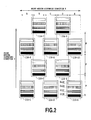
- Fig. 2 is a schematic top view of a printer complex system in the image forming system of Fig. 1 ;
- Fig. 3 is a schematic perspective view showing a part of a printer complex system (upstream side printing apparatuses) in the image forming system of Fig. 1 ;
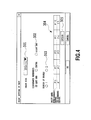
- Fig. 4 illustrates an example setting screen that determines which part of a 1-page image is to be printed by which of the printing apparatuses connected to the information processing device;
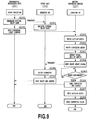
- Fig. 5 is a flow chart showing an example operation sequence of the information processing device that is initiated when a printer driver requests an execution of printing;
- Fig. 6 is a block diagram showing an example configuration of a control system in a printing apparatus according to the first embodiment of this invention.
- Fig. 7 is a block diagram showing an example configuration of a control system in a medium conveying device according to the first embodiment of this invention.
- Fig. 8 is a block diagram showing an example configuration of a signal system for a plurality of printing apparatuses making up the printer complex system
- Fig. 9 is a flow chart showing an interrelated operation sequence among the information processing device, the printing apparatuses of the printer complex system and the medium conveying device in the image forming system;
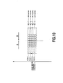
- Fig. 10 is a schematic enlarged view of a printed image at a boundary portion between two adjoining areas being printed by the printing apparatuses arranged as shown in Fig. 2 ;
- Fig. 11 is a schematic enlarged view of a printed image at a boundary portion between two adjoining areas being printed by the printing apparatuses when an ejection failure occurs with an end nozzle of one of the print heads installed in the printing apparatuses;
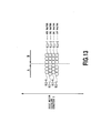
- Fig. 12 is a schematic enlarged view of a printed image at a boundary portion between two adjoining areas being printed by the printing apparatuses when an ejection volume change occurs with one of the print heads installed in the printing apparatuses;
- Fig. 13 is a schematic enlarged view of a printed image at a boundary portion between two adjoining areas being printed by the printing apparatuses when an ejection deflection occurs with nozzles of one of the print heads installed in the printing apparatuses;
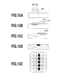
- Figs. 15A-15E explain how density unevenness is produced by a time difference in ink ejection timing
- Fig. 16A and Fig. 16B show dot landing positions in one raster and nozzle drive timings to form the dots when a modified operation of the first embodiment of this invention is applied;
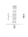
- Fig. 18 schematically show the image degradation of Fig. 17 being alleviated when a modified operation of the first embodiment of this invention is applied;
- Fig. 19 shows an example setting screen used to apply a modified operation of the first embodiment of this invention
- Fig. 20 is a schematic top view of a printer complex system in an image forming system according to a second embodiment of this invention.
- Fig. 22 is a schematic enlarged view of a printed image at a boundary portion between two adjoining areas being printed by the printing apparatuses arranged as shown in Fig. 2 ;
- Fig. 23 is a schematic top view of a printer complex system in an image forming system according to a third embodiment of this invention.
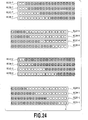
- Fig. 24 is a schematic enlarged view showing a part of Fig. 23 to explain an overlapping arrangement of nozzles
- Fig. 25 is an explanatory diagram showing how stripe-like unevenness occurring between adjoining areas are alleviated by the third embodiment.
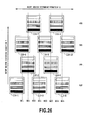
- Fig. 26 is a schematic top view of a printer complex system in an image forming system according to a variation of the third embodiment of this invention.
- the word "print” (also referred to as “image forming”) represents not only forming of significant information, such as characters, graphic image or the like but also represent to form image, patterns and the like on the print medium irrespective whether it is significant or not and whether the formed image elicited to be visually perceptible or not, in broad sense, and further includes the case where the medium is processed.
- print medium represents not only paper to typically used in the printing apparatus but also cloth, plastic film, metal plate, glass, ceramics, wood and leather and the like and any substance which can accept the ink in broad sense.
- ink (also referred to as “liquid”) should be interpreted in a broad sense as well as a definition of the above “printing” and thus the ink, by being applied on the printing media, shall mean a liquid to be used for forming images, designs, patterns and the like, processing the print medium or processing inks (for example, coagulation or encapsulation of coloring materials in the inks to be applied to the printing media).
- an ink ejection opening, a liquid path communicating with the opening, and a device or element installed in the liquid path to generate energy for ink ejection may generally be called a "nozzle" unless otherwise specifically stated.
- Fig. 1 is a block diagram showing an outline of the image forming system according to the first embodiment of this invention.
- the image forming system of this embodiment generally comprises an information processing device 100 and an image forming apparatus 200.
- the image forming apparatus 200 has a medium conveying device 117 and a printer complex system 400, the latter being made up of a plurality of independent engines or printing apparatuses 116-1 to 116-10.
- the information processing device 100 is a source of image data to be formed. It divides one page of image into a plurality of sections in a direction of print medium width and in a conveying direction of print medium and supplies the divided image data to a plurality of printing apparatuses 116-1 to 116-10 making up the printer complex system 400.
- the medium conveying device 117 conveys a print medium 206, whose width corresponds to a range of area that can be printed by an array of printing apparatuses 116-1 to 116-10.
- the medium conveying device 117 also detects a front end of the medium and outputs to the printing apparatuses 116-1 to 116-10 signals defining their print start positions.
- the printer complex system 400 has a plurality (in this example, 10) of printing apparatuses 116-1 to 116-10 so arranged as to print corresponding divided areas of a print medium 206.
- Each of the printing apparatuses executes the printing operation on the assigned print area at a timing defined by the medium conveying device 117.
- Each of the printing apparatuses are provided with print heads 811Y, 811C, 811M, 811K to eject yellow (Y), magenta (M), cyan (C) and black (K) inks, respectively, onto the print medium 206 for full color printing.
- These print heads are supplied the associated color inks from ink sources or ink tanks 203Y, 203M, 203C, 203K, respectively.
- CPU 101 is a central processing unit in charge of an overall system control of the information processing device 100.
- CPU 101 under the control of an operating system (OS) executes processing defined by application programs for generating and editing image data, image dividing program of this embodiment (described later referring to Fig. 5 ), a control program (printer driver) for the printing apparatuses 116-1 to 116-10 and programs corresponding to the procedure of Fig. 5 .
- OS operating system
- a system bus of the CPU 101 is hierarchically structured. More specifically, the CPU is connected through a host/PCI bridge 102 to a local bus, such as PCI bus, and further connected through a PCI/ISA bridge 105 to an ISA bus for connection with devices on these buses.
- a host/PCI bridge 102 to a local bus, such as PCI bus
- a PCI/ISA bridge 105 to an ISA bus for connection with devices on these buses.
- a main memory 103 is a RAM in which is provided a temporary storage area for OS, application programs and the control program. It is also used as a work area for executing the programs. These programs are read from, for example, a hard disk drive HDD 104 and loaded.
- the system bus has a high-speed memory called a cache memory 120 using a SRAM (Static RAM), in which are stored codes and data frequently accessed by the main CPU 101.
- SRAM Static RAM
- the ROM 112 stores a program (BIOS: Basic Input Output System) that controls input/output devices, such as keyboard 114, mouse 115, CDD 111 and FDD 110, connected through an input/output circuit (not shown); an initialization program that is activated when a system is powered on; a self-diagnostic program; and others.
- the EEPROM (Electronic Erasable and Programmable ROM) 113 is a nonvolatile memory to store various permanently usable parameters.
- the video controller 106 continuously and cyclically reads RGB display data written into a VRAM (Video RAM) 107 and continuously transfers them as display refreshing signals to a display 108 such as CRT, LCD and PDP (Plasma Display Panel).
- VRAM Video RAM
- PDP Plasma Display Panel
- the communication interface 109 for the printing apparatuses 116-1 to 116-10 is connected to the PCI bus and may use, for example, bidirectional Centronics interface compatible with IEEE 1284 standard, USB (Universal Serial Bus) and Ethernet (trademark).
- Fig. 1 shows a configuration in which the communication interface 109 is connected with a hub 140, which is further connected to the printing apparatuses 116-1 to 116-10 and the medium conveying device 117. While this embodiment is shown to use the wired type communication interface 109, a wireless type may also be used.
- the print program (printer driver) has a unit for setting areas that are assigned to the plurality of printing apparatuses 116-1 to 116-10 connected to the information processing device 100 (described later with reference to Fig. 4 ). Based on the settings made by this unit, the print program divides one page of image, transfers the divided image data to the associated printing apparatuses 116-1 to 116-10, and instructs them to print the image data.
- the print program since the print program generates print data for the plurality of printing apparatuses 116-1 to 116-10 and transfers the print data to the individual printing apparatuses, the print program itself or the print data generation processing and the print data transfer processing in the program are executed parallelly (multiprocess, multithread), completing the required processing quickly.
- the information processing device 100 is connected to the plurality of printing apparatuses 116-1 to 116-10 and the medium conveying device 117 through the hub 140 to transfer print data and operation start and end commands.
- the individual printing apparatuses 116-1 to 116-10 (generally referenced by numeral 116 when no particular printing apparatus is specified) are also connected with the medium conveying device 117 so that signals representing the detection of the front end of the print medium 206 and the setting of the print start position and signals for synchronizing the medium conveying speed with the printing operation (ink ejection operation) of the individual printing apparatuses are transferred between the printing apparatuses and the medium conveying device.
- Each of the printing apparatuses 116 has four print heads 811Y, 811M, 811C, 811K (generally referenced by numeral 811 when no particular print head is specified) for ejecting yellow (Y), magenta (M), cyan (C) and black (K) inks, respectively, for continuous full-color printing on the print medium 206.
- the order of arrangement of the print heads in the medium conveying direction is the same for all printing apparatuses and therefore the order of color overlapping is also the same.
- Ink ejection openings in each print head are arrayed in a widthwise direction of the print medium (perpendicular to the medium conveying direction) at intervals of 600 dpi (dots/inch) over four inches (about 100 mm).
- the printing apparatuses 116-1 to 116-5 are arranged to cover a maximum overall print width of about 500 mm.
- the printing apparatuses 116-6 to 116-10 are also arranged to cover a maximum overall print width of about 500 mm.
- the printing apparatuses 116-1 to 116-5 and the printing apparatuses 116-6 to 116-10 are located on an upstream side and a downstream side in the medium conveying direction Y (they are also referred to as an upstream side printing apparatus group and a downstream side printing apparatus group).
- a pair of printing apparatuses 116-1 and 116-6, a pair of printing apparatuses 116-2 and 116-7, a pair of printing apparatuses 116-3 and 116-8, a pair of printing apparatuses 116-4 and 116-9 and a pair of printing apparatuses 116-5 and 116-10 can cover the same print areas A, B, C, D and E (100 mm wide), respectively, in a direction of the print medium width X.
- the corresponding print heads can also be assigned different parts of a print area that are divided in the medium conveying direction Y (e.g., different rasters in the print area).
- Fig. 4 shows an example setting screen on the display unit 108 that determines which parts of a 1-page image the printing apparatuses 116-1 to 116-10 connected to the information processing device 100 will cover (print area assignment setting).
- the display of this setting screen is controlled by the CPU 101 executing the print program (printer driver).
- a setting field 301 on the screen of the display unit 108 one can determine an image size to be printed.
- printing apparatuses each with a printable width of 100 mm are arranged as shown in Fig. 2 and Fig. 3 , so it is possible to print an image measuring 500 mm in width and any desired size in length (in the medium conveying direction).
- a setting field 302 allows the user to determine the position of a print medium conveyance reference in the X direction.
- a setting field 303 allows one to choose between using one of the upstream and downstream side printing apparatuses in printing the assigned area and using both. That is, the user can determine whether to perform a 1-pass printing to print all rasters of image data with only one of the upstream and downstream side printing apparatuses or a 2-pass printing to print alternate rasters of image data with both of the printing apparatuses.
- the five 100-mm-wide areas A-E are printed by the five pairs of printing apparatuses 116, with the print area A printed by the pair of printing apparatuses 116-1 and 116-6, the print area B by the pair of printing apparatuses 116-2 and 116-7, the print area C by the pair of printing apparatuses 116-3 and 116-8, the print area D by the pair of printing apparatuses 116-4 and 116-9 and the print area E by the pair of printing apparatuses 116-5 and 116-10.
- which print area is printed by which pair of printing apparatuses is uniquely determined by the physical arrangement of the printing apparatuses (see Fig. 2 ).
- Fig. 2 the example of Fig.
- the image size (width) is selected at "500 mm”
- the conveyance reference is set at a "left end”
- a 2-pass printing is selected. Therefore, in the assignment setting field 304 the printing apparatuses 116-1 to 116-10 (#1 to #10) are shown at positions corresponding to their assigned print areas in the X direction and to their associated rasters in the Y direction. When instructed to start printing, the printing apparatuses print the associated rasters in their assigned print areas, cooperating together to form one image.
- Denoted 305 is a setting field to change the combinations of printing apparatuses (combinations of #1-#5 and combinations of #6-#10) used to print individual rasters. This will be described later.
- the print area assignment setting has been described to be made on the screen of the display unit 108, it may be set using registry information held by OS or system preference setting file.
- the printing apparatuses 116-1 to 116-5 and printing apparatuses 116-6 to 116-10 are arranged to cover print areas not overlapping in the Y direction.
- the printing apparatuses covering the adjoining areas may be arranged to overlap each other at their boundary portion. This will be detailed later.
- Fig. 5 is a flow chart showing an example sequence of steps initiated when the printer driver instructs a printing operation.
- the program determines the print area and rasters to be printed by each of the printing apparatuses 116-1 to 116-10 (step S502).
- the operations to be repeated include one that generates divided image data for each of the printing apparatuses 116-1 to 116-10, based on information indicating which area and rasters in the 1-page image need to be printed (step S504), and one that transfers the generated data from the communication interface 109 (sep S505).
- the divided image data for the individual printing apparatuses 116-1 to 116-10 is generated by and transferred from the information processing device 100.
- step S506 the medium conveying device 117 is started.
- step S507 the program ends this procedure.
- Fig. 6 shows an example configuration of a control system in each printing apparatus 116 according to this embodiment.
- denoted 800 is a CPU that performs an overall control of the printing apparatus 116 according to a program corresponding to the steps of Fig. 9 ; 803 a ROM storing the program and fixed data; 805 a RAM used as a work area; and 814 a nonvolatile EEPROM storing parameters unique to each printing apparatus.
- Designated 802 is an interface controller to connect the printing apparatus to the information processing device 100 via a USB cable.
- Denoted 801 is a VRAM in which to arrange print data for each print head or color.
- a memory controller 804 transfers to the VRAM 801 the divided image data received by the interface controller 802 (data that is generated by step S504 of Fig. 5 and transmitted over from the information processing device 100 by step S505).
- the memory controller also performs control to read print data to be printed by the individual print heads as the printing operation proceeds.
- the CPU 800 analyzes a command attached to the divided image data and issues an instruction for bit-mapping the image data of each color component (print data for each color print head) in the VRAM 801.
- the memory controller 804 writes the image data from the interface controller 802 into the VRAM 801 at high speed and then develops a bit-map of print data for each color print head.
- Denoted 810 is a control circuit to control color print heads 811Y, 811M, 811C, 811K.
- a capping motor 809 is a drive source for a capping mechanism (not shown) that caps a face of the print head 811 formed with ejection openings.
- Denoted 808 is an operation unit including pumps and valves of an ink system (including an ink supply system and a recovery system) described later.
- Denoted 807 is a drive unit to drive the ink system operation unit 808 and the capping motor 809. When the printing apparatus 116 is not used, the capping motor 809 is activated to move the capping mechanism relative to the print heads 811Y, 811M, 811C, 811K to cap them.
- Denoted 806 is an input/output (I/O) port 806.
- the drive unit 807 is connected with motors, operation unit and sensors (not shown) and transfers signals to and from the CPU 800.
- Denoted 812 is a synchronization circuit which receives from the medium conveying device 117 a print medium head signal and a position pulse signal, that is in synchronism with the movement of the medium, and generates a timing signal to execute the printing operation in synchronism with these signals. That is, in synchronism with the position pulse signal produced as the print medium is conveyed, data in the VRAM 801 is read out at high speed by the memory controller 804 which then delivers it through the control circuit 810 to the print heads 811 for color printing.
- the medium conveying device 117 of Fig. 3 is suited for conveying a print medium which is large in the widthwise direction and has an arbitrary size in the conveying direction.
- a media stage 202 for holding flat a print surface of the print medium 206 is installed.
- the similar configuration is also provided for the printing apparatuses 116-6 to 116-10 of the downstream side printing apparatus group not shown in Fig. 3 . Since print media used have various thicknesses, a unit may be added to improve the level of intimate contact between the print medium and the media stage 202 so that the print surface of even a thick medium can be kept flat.
- a conveying motor 205 drives a conveying roller train 205A to convey the print medium in contact with the upper surface of the media stage 202.
- Fig. 7 shows an example configuration of a control system for the medium conveying device 117 according to this embodiment.
- denoted 901 is a CPU that performs an overall control on the medium conveying device according to a program governing a procedure described later with reference to Fig. 9 .
- Denoted 903 is a ROM that stores the program and fixed data.
- a RAM 904 is used as a work memory area.
- Designated 902 is an interface that connects the medium conveying device 117 to the information processing device 100.
- An operation panel 905 has an input unit for the user to enter various data and commands to the image forming apparatus and a display unit for visual display. In this example, it is provided in the medium conveying device.
- Denoted 908 is a suction motor which, as an example of a unit for improving the level of intimate contact between the print medium and the media stage 202, drives a vacuum pump to perform suction from below the media stage 202 through many fine holes formed in a conveying surface of the media stage 202 to keep the print medium in intimate contact with the stage. Then, when a conveying start command is received from the information processing device 100 through the interface 902, the CPU 901 first starts the suction motor 908 to draw the print medium 206 to the upper surface of the media stage 202 by suction.
- Denoted 907 is a drive unit to drive the suction motor 908 and other operation units.
- Denoted 909 is a drive unit for the conveying motor 205.
- Also entered into the logic circuit 912 is an output of a medium sensor 911 provided upstream of the print position in the conveying direction to detect that the front end of the print medium 206 has come near the print start position (the medium sensor 911 may also be added later, rather than being incorporated into the medium conveying device 117 from the beginning). Then, the logic circuit 912 outputs an appropriate print command signal to each printing apparatus according to the distance from the position where the front end of the print medium is detected by the medium sensor 911 to the respective printing apparatuses.
- the printing apparatuses 116-1 to 116-5 of the upstream side printing apparatus group are arranged in two rows in the conveying direction. That is, the printing apparatuses 116-1, 116-3 and 116-5 are arranged at the same position in the conveying direction. At a predetermined distance from these printing apparatuses in the conveying direction, the printing apparatuses 116-2 and 116-4 are arranged at the same position in the conveying direction.
- the logic circuit 912 outputs four print start signals 914-1 to 914-4. Considering errors in the mounting positions of the printing apparatuses, it is possible to make corrections on the print start signals 914-1 to 914-4 for each printing apparatus independently.
- the logic circuit 912 appropriately converts an output of the rotary encoder 910 to produce a print medium position pulse signal 913, and the individual printing apparatuses perform the printing operation in synchronism with the position pulse signal 913.
- the resolution of the position pulse signal may be arbitrarily set. For example, it may be set to match an interval of a plurality of print lines.
- the construction of the print medium conveying unit in the medium conveying device 117 is not limited to the one shown in Fig. 2 that has the fixed media stage 202.
- it may have an endless conveying belt wound around a pair of drums arranged upstream and downstream of the print position in the medium conveying direction.
- a print medium may be carried on the conveying belt as the belt is moved by the rotation of the drums.
- the print medium 206 to be conveyed may be of a cut paper type or a continuous roll paper type.
- Fig. 8 shows an example configuration for signal transfer among the information processing device 100, the medium conveying device 117 and the printing apparatuses 116-1 to 116-10 making up the printer complex system.
- signal paths for the printing apparatuses 116-1 to 116-5 included in the upstream side printing apparatus group 200U are shown detailed while those for the downstream side printing apparatus group 200D are shown simplified.
- One system has a function of transferring divided image data (including operation start and end commands) supplied from the information processing device 100.
- the other system is designed to transfer a print timing defining signal (including print start signal and position pulse) supplied from the medium conveying device 117.
- the first signal system has a hub 140 placed between the information processing device 100 and the printing apparatuses 116-1 to 116-10.
- the hub 140 is connected to the information processing device 100 through a 100 BASE-T standard connector/cable 142 and to the printing apparatuses 116-1 to 116-10 through a 10 BASE-T standard connector/cable 144.
- the print timing defining signal transfer system in the example of Fig. 8 has a transfer control circuit 150 and a synchronization circuit 160. These circuits may be provided as a circuit forming the logic circuit 912.
- the transfer control circuit 150 supplies an output (ENCODER) of the rotary encoder 910 mounted on the shaft of the conveying motor 205 and a detection output (TOF) of the medium sensor 911, that detects the front end of the print medium, to the synchronization circuit 160.
- the synchronization circuit 160 has a print operation permission circuit 166, which calculates a logical AND of operation ready signals PU1-RDY to PU10-RDY from the printing apparatuses 116-1 to 116-10 indicating that the printing apparatuses have received divided image data and which issues a print start signal PRN-START to the printing apparatuses when all the printing apparatuses are found ready to print (after uncapping the print heads).
- the synchronization circuit 160 is also provided with an indication unit 167, such as LEDs, displaying a state associated with the operation ready signals PU1-RDY to PU10-RDY to allow the user to visually check the operation ready state of the printing apparatuses.
- the synchronization circuit 160 is provided with a reset unit 168 for manual forced resetting of the printing apparatuses and with a pause unit 169 for temporarily stopping the printing operation, for example, after one sheet of print medium has been printed.
- the synchronization circuit 160 also has a synchronization signal generation unit 162 and a delay circuit 164.
- the synchronization signal generation unit 162 is designed to generate from the encoder output (ENCODER) a position pulse signal 913 (e.g., 300 pulse signals per inch of travel distance of the print medium) which corresponds to the synchronization signal (HSYNC) for synchronizing all the printing apparatuses during the printing operation.
- the delay circuit 164 generates from the medium front end detection output (TOF) the print start signals 914-1 to 914-4 which are delay signals corresponding to the position of the printing apparatuses in the medium conveying direction.
- TOF medium front end detection output
- the print operation of the printing apparatuses 116-1, 116-3 and 116-5 located on the most upstream side in the print medium conveying direction is started when they receive a print start signal (TOF-IN1) 914-1 being a delay signal that has a delay corresponding to a distance from the medium sensor 911 to the position of each printing apparatus. If the distance from the medium sensor 911 to the position of the individual printing apparatuses is zero, the print start signal 914-1 is supplied almost simultaneously with the detection output TOF.
- TOF-IN1 print start signal
- the print operation of the printing apparatuses 116-2 and 116-4 located on the downstream side is started when they receive a print start signal (TOF-IN2) 914-2 being a delay signal that has a delay corresponding to a distance from the medium sensor 911 to the position of each printing apparatus.
- a print start signal (TOF-IN2) 914-2 being a delay signal that has a delay corresponding to a distance from the medium sensor 911 to the position of each printing apparatus.
- the distance from the medium sensor 911 to these printing apparatuses is set at 450 mm and that the position pulse signal 913 or synchronization signal (HSYNC) has 300 pulses per inch (25.4 mm) of the movement of the print medium.
- the print start signal 914-2 is issued 5,315 pulses after the detection output (TOF).
- print start signal (TOF-IN3) 914-3 being a delay signal that has a delay corresponding to a distance from the medium sensor 911 to the position of these printing apparatuses.
- print start signal (TOF-IN4) 914-4 being a delay signal that has a delay corresponding to a distance from the medium sensor 911 to the position of these printing apparatuses.
- the arrangement pitches in the conveying direction of the printing apparatuses 116-1, 116-3, 116-5, the printing apparatuses 116-2, 116-4, the printing apparatuses 116-6, 116-8, 116-10 and the printing apparatuses 116-7, 116-9 can be set at any desired value. In this embodiment, however, the arrangement pitches of these printing apparatus groups are set equal.
- the print start signal may be supplied independently to the individual printing apparatuses.
- the print heads 811K-811Y are located at different positions in the conveying direction (Y direction). So, upon reception of the print start signal, the print heads are driven according to their positions.
- each of the printing apparatuses 116-1 to 116-10 receives divided print data from the information processing device 100 and independently performs the print operation according to the print timing defining signal supplied from the medium conveying device 117. More specifically, each of the printing apparatuses 116-1 to 116-10 forms a complete unit in terms of the signal system, rather than a configuration in which the print data and print timing are transmitted through one printing apparatus to another.
- Each printing apparatus is provided with units (such as a shift register and a latch circuit) to arrange data for nozzles arrayed in each of the print heads 811Y-811K and perform ink ejection operations at specified timings.
- the printing apparatuses 116-1 to 116-10 each have similar hardware and perform their operation according to the similar software, so that the operation of one printing apparatus does not directly affect the operation of another. These printing apparatuses cooperate as a whole to print one page of image data.
- the print timing defining signals (including the print start signal and position pulse) for the printing apparatuses are supplied from the medium conveying device 117. That is, the printing apparatuses print their print data in response to the instruction from the medium conveying device 117.
- This print start instruction may also be given from the host device 100 as long as it recognizes the print medium conveying state. In that case, the host device 100 may send the data to the printing apparatuses with required delays or add null data proportionate to the required delays to the data that it is going to send to the printing apparatuses.
- Fig. 9 shows operation procedures performed by the information processing device 100, by the printing apparatuses 116 making up the printer complex system 400 and by the medium conveying device 117, and their mutual relationship.
- the information processing device 100 To start a print operation, the information processing device 100 generates divided image data (image data divided in X and Y directions) (step S1001) and send them to the printing apparatuses. Each of the printing apparatuses 116, when it receives the data, uncaps the print heads and develops the data in the VRAM 801 (step S1041). When all the printing apparatuses 116-1 to 116-10 have completed the data reception, the information processing device 100 sends a medium conveying start command to the medium conveying device 117 (step S1002).
- the medium conveying device 117 In response to this command, the medium conveying device 117 first drives the suction motor 908 (step S1061) to make preparations for attracting the print medium 206 to the upper surface of the media stage 202 by suction. Then it drives the conveying motor 205 to start conveying the print medium 206 (step S1062) When the front end of the print medium is detected (step S1063) and the print start position of the print medium reaches the associated printing apparatuses 116-1 to 116-10, the medium conveying device 117 starts sending the print start signals 914-1 to 914-4 and the continuous position pulse signal 913 (step S1064). As described above, the print start signal is output according to the distance from the medium sensor 911 to each printing apparatus.
- step S1042 When the print operation (step S1042) is completed in the printing apparatuses 116, they send a print end status to the information processing device 100 (step S1043) and end the operation. At this time, the print heads 801 are capped by the capping mechanism to prevent nozzles (ejection openings) from drying and clogging.
- the medium conveying device 117 sends a media conveying end status to the information processing device 100 (step S1066) and then stops the suction motor 908 and the conveying motor 205 (step S1067, S1068) before terminating the operation.
- Fig. 10 is an enlarged schematic view of a printed image at a boundary portion between areas A and B of Fig. 2 .
- What are denoted 811-1 and 811-6 and enclosed by a one-dot chain line are print heads installed in the printing apparatuses 116-1 and 116-6 participating in the printing of the area A. Circles inside the one-dot chain line represent nozzles arranged in the print heads or dots formed by them.
- Denoted 811-2 and 811-7 are print heads installed in printing apparatuses 116-2 and 116-7 participating in the printing of the area B. Circles inside represent nozzles arranged in these print heads or dots formed by them.
- This diagram only shows how the print heads are involved in the printing of an image but not physical positions of the print heads. This also applies to Fig. 11 to Fig. 13 , Fig. 17 and Fig. 18 described later.
- odd-numbered (1st and 3rd) rasters in the medium conveying direction Y are printed by the print heads 811-1 and 811-2 of the printing apparatuses 116-1 and 116-2 included in the upstream side printing apparatus group.
- Even-numbered (2nd and 4th) rasters are printed by the print heads 811-6 and 811-7 of the print heads 116-6 and 116-7 included in the downstream side printing apparatus group.
- Fig. 11 is an enlarged schematic view of a printed image at a boundary portion between areas A and B when an ejection failure occurred.
- a continuous linear region devoid of dots that extends in the Y direction is formed, degrading an image quality.
- the printing apparatuses or print heads on the upstream side and those on the downstream side can be made to participate in the printing of alternate rasters, the adverse effects of ejection failure on the printed image can be alleviated.
- This embodiment is not just effective in forming dots with a single color ink. It is also effective when forming secondary color dots using a plurality of color inks. This is because any ejection failure of a color ink may result in a change in the color of a dot of interest.
- Fig. 12 is an enlarged schematic view of a printed image when an overall ink ejection volume of the print head 811-1 is small, thus forming small-diameter dots.
- the system of this embodiment can have the upstream side printing apparatuses or print heads and the downstream side printing apparatuses or print heads participate in the printing of alternate rasters, alleviating adverse effects of the reduced ink ejection volume on the image quality. It should be noted that this embodiment can be effectively applied to addressing not only the problem of small-diameter dots but also the problem of large-diameter dots formed by an ink ejection volume greater than a required one.
- This invention is also effectively applicable where dots are formed at positions deviated from intended ones because of deflections of an ink ejection direction.
- Fig. 13 is an enlarged schematic view of a printed image when dots formed by the print head 811-1 are deviated. Even in such a case, the system of this embodiment can have the upstream side printing apparatuses or print heads and the downstream side printing apparatuses or print heads participate in the printing of alternate rasters, thus alleviating the effects of such dot deviations on the image quality.
- the basic operation of this embodiment involves having the upstream side printing apparatuses or print heads and the downstream side printing apparatuses or print heads participate in the printing of alternate rasters (performing a 2-pass printing with the first setting).
- This produces a basic effect of being able to alleviate image quality degradations caused by ink ejection failures, ink ejection volume variations and dot forming position deviations, while at the same time increasing the printing speed, i.e., an advantage realized by placing the printing apparatuses of the printer complex system described in WO 2004/106068 in a parallel arrangement in the medium conveying direction.
- the upstream side printing apparatuses or print heads and the downstream side printing apparatuses or print heads may be alternately brought into operation every two or more rasters or randomly, as well as every single rasters.
- this embodiment produces the above basic advantage by using two printing apparatus groups of the same printing apparatus arrangement, it also can meet the user demands, such as reduced power consumption, faster printing speed and higher print quality, by performing modified operations such as described below.
- the image forming (1-pass printing with the first setting) can be done using either the upstream or downstream side printing apparatus group.
- one of the upstream side and downstream side printing apparatus groups may be fixedly used according to the setting made on the screen of Fig. 4 .
- the upstream and downstream printing apparatus groups may be alternately switched into operation every predetermined print volume (e.g., one page).
- the following problem arises.
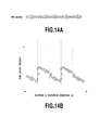
- Fig. 14A and 14B are explanatory diagrams showing positions of dots formed in one raster and nozzle drive timings to form these dots when the printing is done by using only the upstream printing apparatus group.
- Numbers "1" to "5" each enclosed in a circle represent dots formed by the nozzles of the print heads 811 of the printing apparatuses 116-1 to 116-5, respectively.
- the printing apparatuses 116-1, 116-3 and 116-5 are located on the upstream side in the medium conveying direction Y while the printing apparatuses 116-2 and 116-4 are located on the downstream side in the Y direction. So, a time difference t2 from the drive timing for the left-end nozzle of the print head of the printing apparatus 116-3 to the drive timing for the right-end nozzle of the print head of the printing apparatus 116-2 is small (the same is true of the relation between the printing apparatus 116-5 and the printing apparatus 116-4).
- Figs. 15A-D are schematic cross sections showing how adjoining dots are formed by ink droplets being ejected with time delays between them.
- Fig. 15E is a schematic plan view corresponding to Fig. 15D .
- Fig. 15A shows a state immediately before ink droplets B-2 and B-3 ejected from two nozzles on one side of a boundary BS land on a print medium.
- Fig. 15B shows a state in which these ink droplets that have just landed are spreading in a planar direction (horizontally) and penetrating into the print medium and immediately before ink droplets B-4 and B-5 ejected from two nozzles on the other side of the boundary BS land on the print medium.
- Fig. 15C shows a state in which the ink droplets that have landed first are at a last stage of penetration process, with the secondly landed ink droplets beginning to penetrate into the print medium.
- the secondly landed ink droplet B-4 is blocked from penetrating in a depth direction by the firstly landed ink droplet B-3 that has already penetrated and spread horizontally, with the result that the secondly landed ink droplet begins spreading horizontally.
- Figs. 15D and 15E are a schematic cross-sectional view and a schematic plan view showing a state in which the secondly landed ink droplets having completed their penetration process.
- the dot of ink droplet B-4 is blocked from penetrating in the depth direction and forced to spread horizontally.
- Such a spreading of dot increases the local density of ink or colorant on the print medium, resulting in an increase in a density level of the image at the boundary BS.
- a stripe-like density unevenness appears. This problem becomes pronounced as the time difference between the formations of adjoining dots increases because the penetration and horizontal spreading of the firstly landed ink droplets have progressed to a greater extent.
- this embodiment employs a modified operation that makes a second setting which selects appropriate printing apparatuses from the upstream and downstream side printing apparatus groups to make the boundary portions with elevated density levels as nonexistent as possible.
- the printing apparatus 116-5, printing apparatus 116-4, printing apparatuses 116-6 and 116-8, and printing apparatus 116-7 are arranged at equal pitches p (see Fig. 2 ). So, the following three time differences - the time difference from the drive timing of the left-end nozzle of the print head of the printing apparatus 116-5 to the drive timing of right-end nozzle of the printing apparatus 116-4, the time difference from the drive timing of the left-end nozzle of the print head of the printing apparatus 116-4 to the drive timing of the right-end nozzle of the printing apparatus 116-8, and the time difference from the drive timing of left-end nozzle of the print head of the printing apparatus 116-8 to the drive timing of the right-end nozzle of the printing apparatus 116-7 - are all small, equal to t2. The only time when a relatively large time difference t1 occurs is from the drive timing of the right-end nozzle of the print head of the printing apparatus 116-6 to the drive timing of left-end nozzle of the print head of the printing apparatus 116-7.
- the effect of this modified operation depends on the arrangement pitches in the medium conveying direction of the printing apparatuses.
- the arrangement pitches need only be determined so as to satisfy the time difference relation of t2 ⁇ t1. If all the arrangement pitches are set equal as with this example, the desired effect will surely be produced.
- the selection of printing apparatuses described above may be set to be automatically executed when a 1-pass printing is chosen. Alternatively, the above printing apparatus selection may be performed for each print area by clicking on an "option" field 305 in Fig. 4 .
- the procedure of Fig. 5 executes processing to generate divided image data for the associated printing apparatuses or print heads to print.
- Such a change of the combination of printing apparatuses participating in the 1-raster printing, i.e., the second setting, can also be applied to the 2-pass printing.
- the image quality degradations can be made less noticeable by changing the combination of printing apparatuses cooperating in the raster printing, i.e., by changing the print head combination so as to pair the print heads 811-1 and 811-7 of the printing apparatuses 116-1 and 116-7 and to pair the print heads 811-2 and 811-6 of the printing apparatuses 116-2 and 116-6, as shown in Fig. 18 .
- This approach can also be effectively applied to such problems as the ejection volume variations shown in Fig. 12 and the dot position deviations shown in Fig. 13 .
- the change of the combination of printing apparatuses can be performed, for example, by clicking on the "option" field 305 in Fig. 4 .
- this embodiment can also allow the user to select the printing apparatuses or print heads for raster printing and thereby flexibly allocate image data to the printing apparatuses or print head in the arrangement as shown in Fig. 2 .
- the system of this embodiment therefore is capable of minimizing adverse effects of image quality degradations that would otherwise occur in various conditions.
- Fig. 20 is a schematic top view of the printer complex system in the image forming system according to a second embodiment. Its basic system configuration is similar to the first embodiment but the second embodiment differs from the first embodiment in the print heads installed in the printing apparatuses 116-1 to 116-10.
- each of the printing apparatuses is provided with four print heads 811Y, 811M, 811C and 811K to eject yellow (Y), magenta (M), cyan (C) and black (K) inks.
- all the printing apparatuses have the same construction made up of four different print heads.
- the printing apparatuses of the first group are each provided with two print heads 811KU, 811KD for ejecting K ink and two print heads 811CU, 811CD for ejecting C ink.
- the printing apparatuses of the second group are each provided with two print heads 811MU, 811MD for ejecting M ink and two print heads 811YU, 811YD for ejecting Y ink.
- the first printing apparatus group installed on an upstream side has the same number of printing apparatuses as in the first embodiment, or five printing apparatuses, put in a staggered arrangement, while the second printing apparatus group installed on a downstream side has five printing apparatuses in a staggered arrangement.
- the print heads 811KU, 811KD, 811CU, 811CD, 811MU, 811MD, 811YU, 811YD are arranged in this order from the upstream side of the medium conveying direction. So, the orders of color overlapping are also equal in all the print areas.
- Fig. 21 is an enlarged schematic diagram showing an image formed at a boundary portion between the print areas A and B of Fig. 20 by the image forming system of this embodiment.
- reference numerals 811U-1 and 811D-1 enclosed by one-dot chain line represent print heads on the upstream and downstream side (e.g., print heads for K ink), respectively, in the printing apparatus 116-1 assigned to print the area A, with ircles inside the chain lines indicating dots formed by the nozzles of these print heads.
- Denoted 811U-2 and 811D-2 are print heads situated upstream and downstream (e.g., print heads for K ink), respectively, in the printing apparatus 116-2 assigned to print the area B, with circles inside the chain lines representing dots formed by the nozzles of these print heads. Numbers in the circles indicate the order in which the dots are formed. It is noted that this figure explains how the individual print heads are involved in the printing of an image but does not show physical positions of the print heads. This also applies to Fig. 22 and Fig. 23 described later.
- odd-numbered (1st and 3rd) rasters in the medium conveying direction Y are printed by print heads 811U-1 and 811U-2 on the upstream side of the printing apparatuses 116-1 and 116-2.
- Even-numbered (2nd and 4th) rasters are printed by print heads 811D-1 and 811D-2 on the downstream side of the printing apparatuses 116-1 and 116-2.
- Fig. 15 if, when adjoining dots are formed, a difference in droplet landing time between them is large, density unevenness occurs at a boundary portion of the print areas. Although Fig. 15 explains this phenomenon in the medium width direction (X direction), the similar phenomenon also occurs in the medium conveying direction (Y direction).
- a relation between adjoining rasters in each print area e.g., a relation between a dot printed first by the upstream print head 811U-1 and a dot printed third by the downstream print head 811D-1.
- an arrangement pitch of print heads in the printing apparatus be L1 and a medium conveying velocity be V
- T2 (3 ⁇ L1+L2)/V.
- Fig. 22 is an enlarged schematic diagram showing an image formed at a boundary portion between the print areas A and B of Fig. 2 by the image forming system of the first embodiment.
- reference numerals 811-1 and 811-6 enclosed by one-dot chain line represent print heads (e.g., print heads for K ink) in the printing apparatus 116-1 (upstream side) and 116-6 (downstream side) assigned to print the area A, with circles inside the chain lines representing dots formed by these print heads.
- Reference numerals 811-2 and 811-7 represent print heads (e.g., print heads for K ink) in the printing apparatuses 116-2 (upstream side) and 116-7 (downstream side) assigned to print the area B. Circles inside the chain lines represent dots formed by these print heads. The dots are formed in the order of numbers shown in the circles.
- a relation between adjoining rasters in each print area e.g., a relation between a dot printed first by the print head 811-1 of the upstream printing apparatus 116-1 and a dot printed fifth by the print head 811-6 of the downstream printing apparatus 116-6.
- T2 (3 ⁇ L1+L2)/V as similar to the second embodiment.
- the modified operation based on the second setting which appropriately selects desired print heads for use in each print area, can be performed.
- the downstream print head 811D may be used; and for the areas B and D the upstream print head 811U may be used. This reduces the dot formation time difference between the adjoining areas.
- the modified operation based on the second setting which changes a combination of print heads cooperating in the raster printing, can be executed.
- the print head combinations can be changed so as to pair the print heads 811D-1 and 811U-2 and to pair the print heads 811U-1 and 811D-2.
- the printing apparatuses 116-1 to 116-5 and 116-6 to 116-10 are each assigned to print the areas that do not overlap in the Y direction.
- the third embodiment an arrangement in which printing apparatuses covering adjoining print areas are arranged to overlap each other will be explained.
- Fig. 23 is a schematic plan view of a printer complex system of an image forming system according to the third embodiment of this invention. While its basic system configuration is similar to that of the first embodiment, the third embodiment differs from the first embodiment in that the printing apparatuses 116-1 to 116-10 are arranged so that end portions of the print heads 811 overlap near a boundary portion between adjoining print areas in the medium conveying direction (Y direction).
- This overlapping arrangement is used to prevent portions between adjoining print areas from being left unprinted or blank due to degraded arrangement precision of the printing apparatuses 116-1 to 116-5 and 116-6 to 116-10. More precisely, print heads (116-1, 116-6) assigned to the printing of area A and print heads (116-2, 116-7) assigned to the printing of area B, for example, are arranged to extend into each other's area by a few nozzles. In their overlapping region a boundary portion between the adjoining areas is set. Nozzles beyond the boundary portion are not used in the printing operation.
- the information processing device 100 may generate divided image data for a usable nozzle range in each color print head of individual printing apparatuses, add null data to the out-of-use nozzles and supply necessary data to the associated printing apparatuses.
- the information processing device may generate and send divided image data for the usable nozzle range in each color print head of individual printing apparatuses and also send setting data for the usable nozzle range to the individual printing apparatuses so that the printing apparatuses, according to the setting data, can cause only the usable nozzle range to perform ink ejection based on the divided image data.
- the information processing device 100 may generate and send divided image data for the nozzle array range including out-of-use nozzles in each color print head of each printing apparatus and also send setting data for the usable nozzle range to the individual printing apparatuses so that the printing apparatuses, according to the setting data, can extract the image data corresponding to the usable nozzle range and cause only the usable nozzle range to perform ink ejection based on the extracted image data.
- Fig. 24 is an enlarged schematic view of a portion BP of Fig. 23 , explaining an overlapping arrangement of printing apparatuses in this embodiment.
- the print heads of the printing apparatus 116-1 and the printing apparatus 116-2 are arranged to overlap with each other by 16 nozzles; and the print heads of the printing apparatus 116-6 and the printing apparatus 116-2 are also arranged to overlap by 16 nozzles.
- Denoted N are nozzles arrayed in the print heads. Nozzles shown in blank are out-of-use nozzles and those shown hatched are in-use nozzles.
- a gap between the rightmost in-use nozzle in the print head 811K-1 of the printing apparatus 116-1 and the leftmost in-use nozzle of the print head 811K-2 of the printing apparatus 116-2 forms a boundary.
- different boundaries are set for different ink colors, as shown in this figure.
- the boundary is differentiated between the print heads included in the upstream side printing apparatuses and the print heads included in the downstream side printing apparatuses.
- Fig. 25 is one example of image formed by the print heads arranged as shown in Fig. 24 , with odd-numbered rasters formed by the print heads included in the upstream side printing apparatuses and with even-numbered rasters formed by the print heads included in the downstream side printing apparatuses.
- the first and second rasters are made up of K ink dots in a continuous row; the third and fourth rasters are made up of C ink dots in a continuous row; the fifth and sixth rasters are made up of M ink dots in a continuous row; and seventh and eighth rasters are made up of Y ink dots in a continuous row.
- H1 represents a boundary between the rightmost in-use nozzle of the print head 811K-1 and the leftmost in-use nozzle of the print head 811K-2
- H2 represents a boundary between the rightmost in-use nozzle of the print head 811K-6 and the leftmost in-use nozzle of the print head 811K-7
- H3 and H4 represent boundaries between the rightmost in-uses nozzles of the print heads 811C-1 and 811C-6 and the leftmost in-use nozzles of the print head 811C-2 and 811C-7, respectively
- H5 and H6 represent boundaries between the rightmost in-use nozzles of the print heads 811M-1 and 811M-6 and the leftmost in-use nozzles of the print heads 811M-2 and 811M-7, respectively
- H7 and H8 represent boundaries between the rightmost in-use nozzles of the print heads 811Y-1 and 811Y-6 and the leftmost in-use nozzles of the print heads 811Y-2 and 811Y-7, respectively
- This embodiment sets different boundaries for different ink colors and, even in the print heads of the same color ink, differentiates the boundary between the print heads included in the upstream printing apparatuses and the print heads included in the downstream printing apparatuses. Therefore, the positions of boundaries (H1 to H8) are not aligned in the medium conveying direction but scattered in the medium width direction, alleviating the stripe-like density unevenness.
- Fig. 25 represents a case in which dots of primary colors K, C, M or Y are formed in each raster
- the scattering of the boundaries can also be similarly applied where dots of secondary colors R, G, B are formed by color mixing. In this case, too, the stripe-like density unevenness can be made less noticeable.
- a modified operation based on the second setting of changing the combination of printing apparatuses cooperating in the raster printing can also be performed.
- the boundary setting described above can also be done to prevent overlapping of the in-use nozzles or of the out-of-use nozzles in the relation between the print heads 811K-1 and 811K-2 and between the print heads 811K-6 and 811K-7, for example.
- the print heads are so arranged that their ends overlap in the conveying direction (Y direction) near a boundary between adjoining areas, any ejection failures such as shown in Fig. 11 or Fig.
- print heads 811K-1 and 811K-2 may have ejection volume variations, such as shown in Fig. 12 .
- the overlapping range can be determined as required and may not be uniformed.
- the way of scattering the boundaries is not limited to the one shown in Fig. 25 .
- the boundaries may partly overlap.
- the upstream printing apparatus group and the downstream printing apparatus group may be shifted widthwise of the print medium.
- BU1, BU2, BU3 and BU4 roughly represent overlapping ranges between printing apparatuses 116-1 and 116-2, between printing apparatuses 116-2 and 116-3, between printing apparatuses 116-3 and 116-4 and between printing apparatuses 116-4 and 116-5, respectively.
- BD1, BD2, BD3 and BD4 roughly represent overlapping ranges between printing apparatuses 116-6 and 116-7, between printing apparatuses 116-7 and 116-8, between printing apparatuses 116-8 and 116-9 and between printing apparatuses 116-9 and 116-10, respectively.
- the overlapping ranges between the printing apparatuses in the upstream printing apparatus group (e.g., BU1) and the overlapping ranges between the printing apparatuses in the downstream printing apparatus group (e.g., BD1) are not aligned. This can further scatter the boundaries when compared with the arrangement of Fig. 23 , making the stripe-like density unevenness even more difficult to recognize visually.
- Fig. 26 does not allow the combination of printing apparatuses or print heads cooperating in the raster printing to be changed during a 2-pass printing, the combination can be changed during a 1-pass printing using the printing apparatuses 116-6, 116-7, 116-8, 116-4 and 116-5.
- the combination of print heads cooperating in the raster printing may be made changeable for each color.
- color tone including color and density
- any suitable number of types thereof may be used as required.
- the number of printing apparatuses can be determined as required.
- the number of printing apparatus groups can also be determined as required.
- the printing apparatus groups may be arranged, one each in an upstream, a midstream and a downstream position.
- the processing is realized by a control program such as an application software or printer driver. That is, the processing is realized such that program codes of the application software or printer driver are supplied to a system or apparatus and executed by the computer (or CPU or MPU) of the system or apparatus.
- a control program such as an application software or printer driver. That is, the processing is realized such that program codes of the application software or printer driver are supplied to a system or apparatus and executed by the computer (or CPU or MPU) of the system or apparatus.
- the program codes themselves provide a novel feature of the invention. Accordingly, the program codes themselves and a unit for supplying the program codes to the computer by means of communication or a storage medium so as to activate the computer based on the program codes stored therein are also included in the scope of the invention.
- the storage medium for supplying the program codes for example, a hard disk, an optical disk, a magnetooptical disk, a CD-R, a DVD, a magnetic tape, a non-volatile memory card, or a ROM may be used as well as a flexible disk or a CD-ROM.
- the function of the foregoing embodiments can be realized by using a system in which the retrieved program codes are written on a memory provided in a function expanding board inserted into the computer or a memory provided in a function expanding unit connected to the computer, and then a part of or all of processes are executed by the CPU or the like provided in the function expanding board or the function expanding unit on the basis of the command from the program code.
- a system in which the retrieved program codes are written on a memory provided in a function expanding board inserted into the computer or a memory provided in a function expanding unit connected to the computer, and then a part of or all of processes are executed by the CPU or the like provided in the function expanding board or the function expanding unit on the basis of the command from the program code.
- Such a system is also encompassed within the scope of the present invention.
- An image forming system uses printing apparatus groups each consisting of a plurality of printing apparatuses.
- the printing apparatuses hold print heads each provided with nozzles arrayed in a predetermined direction, are arranged two-dimensionally to cooperate with each other in printing rasters extending in the predetermined direction.
- Two printing apparatus groups are arranged in a medium conveying direction.
- the printing apparatuses or print heads located on the upstream side and the downstream side are appropriately set to participate in the printing of the same raster.
- a selection is made of a combination of printing apparatuses or print heads that considers the printed image quality.
Landscapes
- Engineering & Computer Science (AREA)
- Quality & Reliability (AREA)
- Ink Jet (AREA)
- Printers Characterized By Their Purpose (AREA)
- Record Information Processing For Printing (AREA)
Applications Claiming Priority (1)
| Application Number | Priority Date | Filing Date | Title |
|---|---|---|---|
| JP2007284102A JP2009107289A (ja) | 2007-10-31 | 2007-10-31 | 画像形成システム、該システムに用いられる情報処理装置および方法 |
Publications (2)
| Publication Number | Publication Date |
|---|---|
| EP2055487A2 true EP2055487A2 (fr) | 2009-05-06 |
| EP2055487A3 EP2055487A3 (fr) | 2009-12-16 |
Family
ID=40342657
Family Applications (1)
| Application Number | Title | Priority Date | Filing Date |
|---|---|---|---|
| EP08167963A Withdrawn EP2055487A3 (fr) | 2007-10-31 | 2008-10-30 | Système de formation d'images, procédé de traitement d'informations et programme utilisé dans le système |
Country Status (3)
| Country | Link |
|---|---|
| US (1) | US20090109450A1 (fr) |
| EP (1) | EP2055487A3 (fr) |
| JP (1) | JP2009107289A (fr) |
Cited By (2)
| Publication number | Priority date | Publication date | Assignee | Title |
|---|---|---|---|---|
| ITBZ20130044A1 (it) * | 2013-08-21 | 2015-02-22 | Durst Phototechnik Ag | Dispositivo di stampa a getto d'inchiostro con testina di stampa, adatto all'esecuzione di un procedimento di stampa con versatilita' |
| DE102018112030A1 (de) * | 2018-05-18 | 2019-11-21 | Océ Holding B.V. | Druckkopfanordnung für ein Tintendruckgerät |
Families Citing this family (7)
| Publication number | Priority date | Publication date | Assignee | Title |
|---|---|---|---|---|
| JP5325201B2 (ja) * | 2010-12-27 | 2013-10-23 | 田中貴金属工業株式会社 | イリジウム含有合金からなる金属線材 |
| JP6287042B2 (ja) * | 2013-10-17 | 2018-03-07 | セイコーエプソン株式会社 | 記録装置および記録装置による印刷方法 |
| US10052897B2 (en) | 2014-05-28 | 2018-08-21 | Hewlett-Packard Development Company, L.P. | Arranging image data segments in printing devices |
| JP2017136835A (ja) * | 2016-02-02 | 2017-08-10 | キヤノン株式会社 | 画像形成装置、制御方法及びプログラム |
| US9738066B1 (en) * | 2016-03-25 | 2017-08-22 | Xerox Corporation | System and method for image data processing for inoperable inkjet compensation in an inkjet printer |
| JP7077541B2 (ja) * | 2017-07-11 | 2022-05-31 | 富士フイルムビジネスイノベーション株式会社 | 画像形成システム及びプログラム |
| NL2027440B1 (en) * | 2021-01-26 | 2022-08-19 | Canon Production Printing Holding Bv | Page-wide Print Head Array and Printer Comprising said Page-wide Print Head Array |
Citations (1)
| Publication number | Priority date | Publication date | Assignee | Title |
|---|---|---|---|---|
| WO2004106068A1 (fr) | 2003-06-02 | 2004-12-09 | Canon Finetech Inc. | Dispositif de formation d'image, systeme complexe d'impression et dispositif d'acheminement de support pour ce dispositif, unite de traitement d'informations destinee a fournir des donnees d'image au dispositif de formation d'image, et systeme de formation d'image et procede de formation d'image associes |
Family Cites Families (4)
| Publication number | Priority date | Publication date | Assignee | Title |
|---|---|---|---|---|
| JP2002103598A (ja) * | 2000-07-26 | 2002-04-09 | Olympus Optical Co Ltd | プリンタ |
| US7226143B2 (en) * | 2002-10-11 | 2007-06-05 | Seiko Epson Corporation | Printing apparatus |
| US7527354B2 (en) * | 2005-01-07 | 2009-05-05 | Canon Finetech Inc. | Recording system |
| US7967407B2 (en) * | 2006-02-03 | 2011-06-28 | R.R. Donnelley | Use of a sense mark to control a printing system |
-
2007
- 2007-10-31 JP JP2007284102A patent/JP2009107289A/ja not_active Withdrawn
-
2008
- 2008-10-27 US US12/258,943 patent/US20090109450A1/en not_active Abandoned
- 2008-10-30 EP EP08167963A patent/EP2055487A3/fr not_active Withdrawn
Patent Citations (1)
| Publication number | Priority date | Publication date | Assignee | Title |
|---|---|---|---|---|
| WO2004106068A1 (fr) | 2003-06-02 | 2004-12-09 | Canon Finetech Inc. | Dispositif de formation d'image, systeme complexe d'impression et dispositif d'acheminement de support pour ce dispositif, unite de traitement d'informations destinee a fournir des donnees d'image au dispositif de formation d'image, et systeme de formation d'image et procede de formation d'image associes |
Cited By (2)
| Publication number | Priority date | Publication date | Assignee | Title |
|---|---|---|---|---|
| ITBZ20130044A1 (it) * | 2013-08-21 | 2015-02-22 | Durst Phototechnik Ag | Dispositivo di stampa a getto d'inchiostro con testina di stampa, adatto all'esecuzione di un procedimento di stampa con versatilita' |
| DE102018112030A1 (de) * | 2018-05-18 | 2019-11-21 | Océ Holding B.V. | Druckkopfanordnung für ein Tintendruckgerät |
Also Published As
| Publication number | Publication date |
|---|---|
| US20090109450A1 (en) | 2009-04-30 |
| JP2009107289A (ja) | 2009-05-21 |
| EP2055487A3 (fr) | 2009-12-16 |
Similar Documents
| Publication | Publication Date | Title |
|---|---|---|
| EP2055487A2 (fr) | Système de formation d'images, procédé de traitement d'informations et programme utilisé dans le système | |
| US6604806B1 (en) | High resolution printing | |
| US11312128B2 (en) | Head driving device, liquid discharge apparatus, and head driving method | |
| JP2008001091A (ja) | アレイ型マルチパスインクジェットプリンタおよびアレイ型マルチパスインクジェットプリンタの動作方法 | |
| JP4594902B2 (ja) | 液体吐出装置、及び液体吐出方法 | |
| CN113858827A (zh) | 印刷装置及印刷方法 | |
| EP0738068A2 (fr) | Techniques d'impression aléatone pour imprimantes à encre liquide | |
| JP4513802B2 (ja) | 印刷装置 | |
| JP3591286B2 (ja) | タイミング調整方法、印字装置及び調整パターン作成方法 | |
| US9796176B2 (en) | Image forming apparatus, method of forming image, and non-transitory recording medium | |
| JP5747517B2 (ja) | 記録方法及び記録装置 | |
| US7909422B2 (en) | Printing method, printing system, and print control apparatus | |
| US20100165028A1 (en) | Coding and marking printing system | |
| US7344225B2 (en) | Printing method, printing system, and print control apparatus | |
| US7367645B2 (en) | Printing method and printing apparatus | |
| EP1495875B1 (fr) | Impression a resolution non uniforme | |
| US10850539B2 (en) | Printing system, printing apparatus, and printing control method | |
| US10654264B2 (en) | Printing system, printing control apparatus, and printing control method | |
| JP2004066595A (ja) | 記録装置およびレジストレーション用パターンの記録方法 | |
| JP5898423B2 (ja) | インクジェット記録装置および記録方法 | |
| JPH115319A (ja) | 印字位置調整方法およびこの調整方法を利用した印字装置並びに印字位置調整制御プログラムを格納した記録媒体 | |
| US20110216114A1 (en) | Printing apparatus and method of controlling printing apparatus | |
| JP2008155378A (ja) | 印刷方法、及び、印刷装置 | |
| US7364250B2 (en) | Printing method, printing system, and print control apparatus | |
| JP2007130983A (ja) | 印刷システムおよびその制御方法 |
Legal Events
| Date | Code | Title | Description |
|---|---|---|---|
| PUAI | Public reference made under article 153(3) epc to a published international application that has entered the european phase |
Free format text: ORIGINAL CODE: 0009012 |
|
| 17P | Request for examination filed |
Effective date: 20081030 |
|
| AK | Designated contracting states |
Kind code of ref document: A2 Designated state(s): AT BE BG CH CY CZ DE DK EE ES FI FR GB GR HR HU IE IS IT LI LT LU LV MC MT NL NO PL PT RO SE SI SK TR |
|
| AX | Request for extension of the european patent |
Extension state: AL BA MK RS |
|
| PUAL | Search report despatched |
Free format text: ORIGINAL CODE: 0009013 |
|
| AK | Designated contracting states |
Kind code of ref document: A3 Designated state(s): AT BE BG CH CY CZ DE DK EE ES FI FR GB GR HR HU IE IS IT LI LT LU LV MC MT NL NO PL PT RO SE SI SK TR |
|
| AX | Request for extension of the european patent |
Extension state: AL BA MK RS |
|
| RIC1 | Information provided on ipc code assigned before grant |
Ipc: G06K 15/10 20060101ALI20091110BHEP Ipc: B41J 3/54 20060101ALI20091110BHEP Ipc: B41J 2/155 20060101AFI20090225BHEP |
|
| AKX | Designation fees paid |
Designated state(s): DE FR GB |
|
| STAA | Information on the status of an ep patent application or granted ep patent |
Free format text: STATUS: THE APPLICATION IS DEEMED TO BE WITHDRAWN |
|
| 18D | Application deemed to be withdrawn |
Effective date: 20100617 |