EP2055509A1 - Système de suspension ayant une commande traverse pendulaire hydraulique - Google Patents
Système de suspension ayant une commande traverse pendulaire hydraulique Download PDFInfo
- Publication number
- EP2055509A1 EP2055509A1 EP07119870A EP07119870A EP2055509A1 EP 2055509 A1 EP2055509 A1 EP 2055509A1 EP 07119870 A EP07119870 A EP 07119870A EP 07119870 A EP07119870 A EP 07119870A EP 2055509 A1 EP2055509 A1 EP 2055509A1
- Authority
- EP
- European Patent Office
- Prior art keywords
- machine
- frame
- hydraulic
- equalizer bar
- suspension system
- Prior art date
- Legal status (The legal status is an assumption and is not a legal conclusion. Google has not performed a legal analysis and makes no representation as to the accuracy of the status listed.)
- Granted
Links
- 239000000725 suspension Substances 0.000 title claims abstract description 41
- 239000012530 fluid Substances 0.000 claims abstract description 34
- 238000000034 method Methods 0.000 claims abstract description 16
- 238000006073 displacement reaction Methods 0.000 claims description 13
- 230000001133 acceleration Effects 0.000 claims description 8
- 230000008878 coupling Effects 0.000 claims description 2
- 238000010168 coupling process Methods 0.000 claims description 2
- 238000005859 coupling reaction Methods 0.000 claims description 2
- 230000003247 decreasing effect Effects 0.000 claims description 2
- 239000002689 soil Substances 0.000 description 9
- 238000005452 bending Methods 0.000 description 4
- 230000001276 controlling effect Effects 0.000 description 3
- 241000510097 Megalonaias nervosa Species 0.000 description 1
- 230000000903 blocking effect Effects 0.000 description 1
- 238000012986 modification Methods 0.000 description 1
- 230000004048 modification Effects 0.000 description 1
- 230000007935 neutral effect Effects 0.000 description 1
- 230000001105 regulatory effect Effects 0.000 description 1
- 239000011435 rock Substances 0.000 description 1
- 239000007787 solid Substances 0.000 description 1
Images



Classifications
-
- B—PERFORMING OPERATIONS; TRANSPORTING
- B60—VEHICLES IN GENERAL
- B60G—VEHICLE SUSPENSION ARRANGEMENTS
- B60G17/00—Resilient suspensions having means for adjusting the spring or vibration-damper characteristics, for regulating the distance between a supporting surface and a sprung part of vehicle or for locking suspension during use to meet varying vehicular or surface conditions, e.g. due to speed or load
- B60G17/005—Suspension locking arrangements
-
- B—PERFORMING OPERATIONS; TRANSPORTING
- B60—VEHICLES IN GENERAL
- B60G—VEHICLE SUSPENSION ARRANGEMENTS
- B60G17/00—Resilient suspensions having means for adjusting the spring or vibration-damper characteristics, for regulating the distance between a supporting surface and a sprung part of vehicle or for locking suspension during use to meet varying vehicular or surface conditions, e.g. due to speed or load
- B60G17/02—Spring characteristics, e.g. mechanical springs and mechanical adjusting means
- B60G17/04—Spring characteristics, e.g. mechanical springs and mechanical adjusting means fluid spring characteristics
-
- B—PERFORMING OPERATIONS; TRANSPORTING
- B62—LAND VEHICLES FOR TRAVELLING OTHERWISE THAN ON RAILS
- B62D—MOTOR VEHICLES; TRAILERS
- B62D55/00—Endless track vehicles
- B62D55/08—Endless track units; Parts thereof
- B62D55/084—Endless-track units or carriages mounted separably, adjustably or extensibly on vehicles, e.g. portable track units
- B62D55/0842—Tracked vehicle with track carriages suspended on three points, e.g. by an equaliser bar
-
- B—PERFORMING OPERATIONS; TRANSPORTING
- B62—LAND VEHICLES FOR TRAVELLING OTHERWISE THAN ON RAILS
- B62D—MOTOR VEHICLES; TRAILERS
- B62D55/00—Endless track vehicles
- B62D55/08—Endless track units; Parts thereof
- B62D55/104—Suspension devices for wheels, rollers, bogies or frames
- B62D55/116—Attitude or position control of chassis by action on suspension, e.g. to compensate for a slope
-
- B—PERFORMING OPERATIONS; TRANSPORTING
- B60—VEHICLES IN GENERAL
- B60G—VEHICLE SUSPENSION ARRANGEMENTS
- B60G2200/00—Indexing codes relating to suspension types
- B60G2200/30—Rigid axle suspensions
- B60G2200/32—Rigid axle suspensions pivoted
-
- B—PERFORMING OPERATIONS; TRANSPORTING
- B60—VEHICLES IN GENERAL
- B60G—VEHICLE SUSPENSION ARRANGEMENTS
- B60G2200/00—Indexing codes relating to suspension types
- B60G2200/30—Rigid axle suspensions
- B60G2200/32—Rigid axle suspensions pivoted
- B60G2200/322—Rigid axle suspensions pivoted with a single pivot point and a straight axle
-
- B—PERFORMING OPERATIONS; TRANSPORTING
- B60—VEHICLES IN GENERAL
- B60G—VEHICLE SUSPENSION ARRANGEMENTS
- B60G2202/00—Indexing codes relating to the type of spring, damper or actuator
- B60G2202/40—Type of actuator
- B60G2202/41—Fluid actuator
- B60G2202/413—Hydraulic actuator
-
- B—PERFORMING OPERATIONS; TRANSPORTING
- B60—VEHICLES IN GENERAL
- B60G—VEHICLE SUSPENSION ARRANGEMENTS
- B60G2400/00—Indexing codes relating to detected, measured or calculated conditions or factors
- B60G2400/05—Attitude
- B60G2400/051—Angle
- B60G2400/0511—Roll angle
-
- B—PERFORMING OPERATIONS; TRANSPORTING
- B60—VEHICLES IN GENERAL
- B60G—VEHICLE SUSPENSION ARRANGEMENTS
- B60G2400/00—Indexing codes relating to detected, measured or calculated conditions or factors
- B60G2400/05—Attitude
- B60G2400/053—Angular acceleration
- B60G2400/0531—Roll acceleration
-
- B—PERFORMING OPERATIONS; TRANSPORTING
- B60—VEHICLES IN GENERAL
- B60G—VEHICLE SUSPENSION ARRANGEMENTS
- B60G2400/00—Indexing codes relating to detected, measured or calculated conditions or factors
- B60G2400/25—Stroke; Height; Displacement
- B60G2400/252—Stroke; Height; Displacement vertical
Definitions
- the present disclosure is directed to a suspension system, in particular to a suspension system having hydraulic equalizer bar control.
- Machines having traction devices that generally extend front to back are known to experience traction problems on uneven soil conditions when the traction devices are rigidly coupled to the frame.
- Larger machines therefore commonly include an equalizer bar that interconnects the front parts of opposing traction devices.
- the equalizer bar may be pivotally connected to the machine frame and may allow a rocking movement of the front parts of the traction devices, so that the traction devices may follow the soil on uneven terrain. This allows productivity of the machine to be maintained under rough soil conditions.
- the equalizer bar When the machine is on smooth soil, however, the equalizer bar may complicate operation of the machine, and may cause excessive vibration of the machine. Especially when driving the machine on soil with close ridges, or when the machine is driven on the road, heavy machine pitch may occur that is uncomfortable for the operator and that increases wear on the machine.
- a machine which includes such a lockable equalizer bar is the Caterpillar Pipe layer 561N.
- flanges with bolt holes have been provided on the frame and on the equalizer bar, which may be locked together via a locking bolt when the bolt holes are aligned in the neutral position of the equalizer bar.
- the disclosed suspension system is directed at alleviating one or more of the disadvantages set forth above.
- One aspect of the present disclosure is directed to a suspension system for a machine having an equalizer bar that interconnects opposing traction devices extending generally front to back along a frame of the machine.
- the system includes at least one hydraulic component acting between the equalizer bar and the frame, and at least one valve fluidly connected to the at least one hydraulic component.
- the at least one valve is in use controlled to influence fluid flow to the actuator in order to selectively allow movement of the equalizer bar relative to the frame.
- Another aspect of the disclosure is directed to a method of controlling a suspension system of a machine having an equalizer bar that interconnects two opposing traction devices extending along a frame of the machine.
- the method comprises influencing a flow of hydraulic fluid in the suspension system in order to selectively allow movement of the equalizer bar relative to the frame.
- Fig. 1 is an isometric illustration of an exemplary disclosed machine
- Fig. 2 is a schematic illustration of an exemplary disclosed suspension system that may be used with the machine of Fig. 1 ;
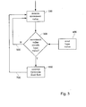
- Fig. 3 is a flow chart illustrating an exemplary disclosed method of controlling the suspension system of Fig. 2 ; and Fig. 4 is a flow chart illustrating another exemplary disclosed method of controlling the suspension system of Fig. 2 .
- Fig. 1 shows an embodiment of a machine 1 having two opposing traction devices 2 that extend generally front to back along the frame 3 of the machine 1.
- the term 'generally extending front to back' is in this specification meant to express the general direction in which the traction devices 2 extend along the frame 3, that is to say that the traction devices 2 do not necessarily extend fully or exactly from the back to the front the machine 1.
- the machine 1 may for example be a bulldozer, a track loader, a motor grader or a skid steer loader.
- the machine 1, as shown in Fig. 1 is a bulldozer.
- the machine 1 may be propelled by any drive arrangement (not shown), which may typically be a pair of opposing drive shafts.
- the drive shafts may for example be arranged to drive sprockets 4 at a back end of the traction device 2.
- the traction device 2 may rigidly connect sprockets 4 at a front end 5 of the machine 1 to the sprockets 4 at the rear end 6 of the machine 1.
- Each traction device 2 may include a track roller frame 7 carrying track elements 8 that are interconnected to form an endless drive track 9 around the sprockets 4 at the front end 5 and rear end 6 of one side of the machine 1, as shown in the exemplary disclosed embodiment of Fig. 1 .
- the drive shafts may be arranged to directly drive the sprockets 4 at the back end of the machine 1.
- the drive shafts may drive the track elements, for example via a final drive arrangement engaging the upper part of the track 9 near the drive sprockets 4 at the rear end 6 of the machine 1.
- the traction device 2 may also have other drive means than tracks 9.
- the traction device 2 may for example be arranged to include drive support beams generally extending front to back along the frame 3 and carrying wheels having tires (not shown), such as is the case in a motor grader.
- the machine 1 may include a suspension system 10 that interconnects front parts 11 of the opposing traction devices 2 to the frame 3 of the machine 1.
- the suspension system 10 may include an equalizer bar 13.
- the equalizer bar 13 may be connected pivotally to the machine frame 3 about an axis 14 that extends longitudinal to the frame 3, so that it allows a rocking movement of the front parts 11 of the traction devices 2. This may be realized via a pivot connection 12.
- the pivot connection 12 may, for example, be a hinge, but may also be any other type of pivot arrangement, such as a ball joint.
- Rear parts 15 of the traction devices 2 may likewise be pivotally connected to the machine frame 3 about an pivot axle that extends laterally to the frame 3, so that the traction devices 2 may oscillate about a lateral axis 16 through the pivot axle when the front parts 11 perform a rocking movement about the longitudinal axis 14.
- Such pivot axle may coincide with the drive shafts, for example when the sprockets 4 at the rear end 6 of the machine 1 are driven directly by the drive shafts.
- such a pivot axle may be a separate component extending between the frame 3 of the machine 1 and the track roller frame 7 or support beam, for example in an embodiment with a final drive arrangement engaging the upper part of the track 9 near the drive sprockets 4 at the rear end 6 of the machine 1.
- the equalizer bar 13 may couple the front parts 11 of the traction devices 2 via connections 27 that allow a degree of movement, but yet withstand severe loading.
- a connection 27 may for example include a pin associated with the equalizer bar 13, and a fastener extending through both the pin and the frame 3.
- the suspension system 10 may include at least one hydraulic component acting between the frame 3 and the equalizer bar 13.
- the number of hydraulic components may vary, as well as the type of hydraulic component.
- the hydraulic component may for example, be embodied as a hydraulic motor that would at least partially form the pivot connection 12 between the equalizer bar 13 and the frame 3.
- the hydraulic component may be a hydraulic actuator 17.
- the hydraulic component shall be referred to as hydraulic actuator 17.
- the hydraulic component may also be embodied as another type of hydraulic component than a hydraulic actuator
- the hydraulic component may be a hydraulic motor as discussed above.
- the hydraulic component may be an accumulator.
- the hydraulic actuator 17 may embody a linear hydraulic cylinder.
- Such a hydraulic cylinder may in one embodiment be a single action cylinder, but may in another embodiment for example be a double action cylinder.
- the two hydraulic actuators 17 may each act on the equalizer bar 13 between a central portion 18, which may be pivotally connected to the frame 3, and an end portion 19, which may be connected to the traction device 2.
- the hydraulic actuators 17 may not only act oppositely to influence rocking movement about longitudinal axis 14, but may also act jointly to counter bending movement of the equalizer bar 13 about longitudinal axis 14. Such bending movement may cause the end portions 19 of the equalizer bar 13 to move out of line with the central portion 18 of the equalizer bar 13, which would result in pitch of the machine 1. This shall be discussed further in the next section.
- the suspension system 10 may further include at least one valve 20.
- the valve 20 may be fluidly connected to the at least one actuator 17, for example via hydraulic lines 23 of a hydraulic circuit 24.
- the valve 20 may be arranged in a hydraulic line 23 that interconnects the two hydraulic actuators 17.
- the valve 20 may be of any type, for example an on/off valve, a ball valve, a solenoid valve or a restrictor.
- the valve 20 may be an electro-hydraulic restrictor.
- the valve 20 may be arranged to influence hydraulic flow continuously, stepwise or in a binary fashion.
- valve 20 may be controlled to influence fluid flow to the hydraulic actuator 17 in order to selectively allow movement of the equalizer bar 13 relative to the frame 3.
- the valve 20 may be operated mechanically, electrically, hydraulically and/or pneumatically.
- a mechanically operated valve 20 there may, for example, be provided a mechanical linkage to operate a ball type valve 20, or an electronic slave control arrangement.
- the valve 20 may also be operated via a controller 21.
- the controller 21 may, for example include a logic circuit or computer that may be operatively connected to an electrically controlled valve 20.
- the controller 21 may be a computer, which may for example be part of a hydraulics management system of the machine 1, and the valve 20 may be an electrically controlled restrictor.
- the suspension system 10 may further include at least one sensor 22, generating an input signal for the controller 21 that is indicative of movement of the equalizer bar 13 relative to the frame 3, so that the controller 21 may operate the valve 20 based on a movement value represented by said input signal.
- the sensor 22 may be of various types.
- the sensor 22 may, for example, be one of a displacement sensor, an acceleration sensor and an inclinometer.
- a displacement sensor may for example be embodied as a linear displacement sensor arranged in a linear hydraulic actuator 17 acting between the equalizer bar 13 an the frame 3 that measures the distance or displacement of the equalizer bar 13 relative to the frame 3.
- a displacement sensor may for example be embodied as an angular displacement sensor arranged in the connection between the rear part 15 of the traction device 2 and the frame 3 that measures the angle or angular displacement of the traction device 2 relative to the frame 3.
- a displacement sensor may be embodied as an angular displacement sensor arranged in the pivotable connection 12 between the equalizer bar 13 and the frame 3.
- an acceleration sensor may be embodied as an angular acceleration sensor arranged in a hydraulic motor in the pivotable connection 12 between the equalizer bar 13 and the frame 3, measuring the angular acceleration of the equalizer bar 13 relative to the frame 3.
- an inclinometer may be embodied as a gyroscopic inclinometer supported on the frame 3 of the machine 1, measuring the angle of the machine frame 3 relative to the ground.
- the number of sensors 22 may vary. The sensors 22 may be preferably placed relatively high above the ground, so that they may be shielded from dirt and debris. In the exemplary disclosed embodiment shown in Fig.
- a single sensor 22 embodied as an angular displacement sensor or a gyroscope based inclinometer may for example be located at the central portion 18 of the equalizer bar 13 or in the pivot connection 12. However, sensors 22 may also be placed in other locations.
- the suspension system 10 may include at least one hydraulic accumulator 25 to dampen movement of the equalizer bar 13 relative to the frame 3, and/or to store hydraulic energy of the hydraulic circuit 24.
- a hydraulic accumulator 25 may be used in addition to a hydraulic actuator 17, or in stead of a hydraulic accumulator 25. For example, as shown in dotted lines in Fig.
- a single hydraulic accumulator 25 may be used in addition to the hydraulic actuators 17 to dampen the movement of the equalizer bar 13 relative to the frame 3 when the valve 20 allows flow of hydraulic fluid.
- a pair of hydraulic accumulators may be arranged in lieu of the hydraulic actuators 17 shown in Fig. 2 (not shown). In such a configuration, the hydraulic accumulators may be mechanically coupled between the equalizer bar 13 and the frame 3 to act as hydraulic components 17.
- the suspension system 10 may also include a pressure supply 26, for example a hydraulic pump. In the exemplary embodiment of Fig. 2 , the pressure supply 26 may be connected via hydraulic lines 23 to the hydraulic actuators 17. Check valves 28 may be included in the hydraulic lines 23 to keep the hydraulic actuators 17 pressurized.
- Fig. 3 and Fig. 4 illustrate an exemplary method of operating the suspension system 10. Fig. 3 and Fig. 4 shall be discussed in the next section.
- the disclosed suspension system 10 may be used in any type of mobile machine to suspend traction devices 2 onto a machine frame 3, such that it may switch easily between a rockable or fixed configuration.
- the disclosed machine suspension system 10 may operate as follows. To move the machine 1, the traction devices 2 may be driven in a conventional way. That is, in the machine 1 of the exemplary disclosed embodiment of Fig. 1 and Fig. 2 , the sprockets 4 may engage the track elements 8 so that the opposing drive tracks 9 move forward or backward on the track roller frames 7. The drive tracks 9 engage the ground, and the machine 1 moves. If the speed and direction of movement of both drive tracks 9 are the same, the machine 1 moves straight, for example forward or backward. If the speed or direction of both drive tracks 9 differs, the machine 1 moves along a curve or pivots without travel. During operation, the pressure supply 26 pressurizes hydraulic fluid in hydraulic lines 23 of the hydraulic circuit 24 of the suspension system 10.
- the flow of fluid in the hydraulic circuit 24 of the suspension system 10 may be influenced such that the hydraulic actuator 17 acting between the frame 3 and the equalizer bar 13 inhibits movement of the equalizer bar 13 relative to the frame 3.
- this may be achieved by controller 21 regulating the valve 20 to block hydraulic fluid flow in the hydraulic line 23 that extends between the hydraulic actuators 17.
- This blockage may lock up the hydraulic circuit 24, and the hydraulic actuators 17 acting on the equalizer bar 13 between the central portion 18 and the end portions 19 may prevent rocking movement of the equalizer bar 13 about longitudinal axis 14.
- the locking of hydraulic circuit 24 places machine 1 in a rigid configuration, in which the traction devices 2 may be rigidly coupled to the frame 3. Such a rigid coupling may simplify operation of the machine 1, and may reduce vibration.
- the controller 21 may regulate the valve 20 to allow a flow of hydraulic fluid to the hydraulic actuator 17 or between paired hydraulic actuators 17.
- the hydraulic actuator 17 may allow rocking movement of the equalizer bar 13 about longitudinal axis 14.
- the controller 21 may regulate the restrictor valve 20 to allow hydraulic fluid flow in the hydraulic line 23 that extends between the hydraulic actuators 17.
- the hydraulic fluid flow through the hydraulic circuit 24 may allow movement of the hydraulic actuators 17 acting on the equalizer bar 13 between the central portion 18 and the end portions 19, so that rocking movement of the equalizer bar 13 about longitudinal axis 14 may take place.
- the front parts 11 of the traction devices 2 that are connected to the end portions 19 of the equalizer bar 13 via connections 27 may follow the rocking movement. In doing so, the rear parts 15 of the traction devices 2 that are pivotally connected to the machine frame 3 may oscillate about the lateral axis 16. In the rockable configuration, the traction devices 2 may rock relative to the frame 3 and may follow the soil on uneven terrain. By allowing traction devices 2 to follow the terrain, the productivity of the machine 1 may be maintained, even under rough soil conditions.
- the machine 1 may be switched easily between locked and rockable configurations.
- the flow of hydraulic fluid may be influenced in a binary fashion, such that movement of the equalizer bar 13 may either be allowed or disallowed. However, the flow may also be influenced stepwise or continuously, for example to allow various degrees of dampened movement.
- a pair of hydraulic actuators 17 is arranged such that each hydraulic actuator 17 acts between a central portion 18 and end portion 19 of the of the equalizer bar 13, the hydraulic actuators 17 may also prevent bending movement of the equalizer bar 13 about the longitudinal axis 14.
- a reduction of such bending movement may keep the end portions 19 of the equalizer bar 13 more on a straight line with the central portion 18 of the equalizer bar 13, which may help to reduce pitch of the machine 1 during travel.
- heavy machine pitch may thus be prevented, which may significantly reduce machine vibration. This may increase operator comfort and reduce wear on the machine 1. If the flow of hydraulic fluid is influenced incrementally or continuously, the suspension system 10 may then provide the operator with a form of ride control.
- the hydraulic actuators 17 may be pressurized using a pressure supply 26 that feeds hydraulic fluid to the hydraulic circuit 24.
- Check valves 28 included in the hydraulic lines 23 may prevent back flow of hydraulic fluid.
- a hydraulic accumulator 25 with a second restrictor valve 20 may be included in the hydraulic circuit 24 to dampen the movement of the equalizer bar 13 relative to the frame 3 when the restrictor valves 20 allow hydraulic fluid flow.
- the hydraulic component is embodied as one or more hydraulic accumulators 25 that are mechanically coupled between the equalizer bar 13 and the frame 3 in the rockable configuration
- the movement of the equalizer bar 13 relatively to the frame 3 may be dampened by the hydraulic fluid flow passing through the accumulators 25.
- the valve 20 may prevent movement of the equalizer bar 13 relative to the frame 3 by blocking flow of hydraulic fluid.
- the flow of hydraulic fluid may be influenced manually or automatically.
- an operator may adjust a valve manually through a linkage or through electronic slave control.
- the flow may be influenced automatically using an automated controller 21 and a sensor 22 generating an input signal for the controller 21 that is indicative of movement of the equalizer 13 bar relative to the frame 3.
- a flow chart is depicted with an exemplary disclosed method of automatically operating the suspension system 10.
- the controller 21 may receive an input movement value (step 200).
- the input movement value may for example be angular displacement of a traction device 2 relative to the frame 3.
- the input movement value may for example be angular acceleration of the equalizer bar 13 relative to the frame 3.
- the controller 21 may compare the received movement value to a base value (step 300).
- the base value may be fixed or variable.
- a variable base value may for example be given in by the operator.
- a variable base value may be for example be read from an electronic map (step 400).
- Such an electronic map may, for example, include acceleration values that vary with changing speeds of the machine 1.
- the controller 21 may influence the flow of hydraulic fluid. If the input movement value does not exceed the base value, the controller 21 may take no action and may go back to receiving new input (step 500). If the input movement value exceeds the base value, the controller 21 may restrict hydraulic fluid flow via valve 20 (step 600), and may return to receiving new input (step 700). Depending on the type of valve 20, the fluid flow may be influenced stepwise or continuously.
- the machine 1 may switch automatically between the rockable and fixed configurations, while the switching behavior may, for example, vary depending on the speed of the machine 1.
- the degree in which the suspension system 10 dampens the movement of the equalizer bar 13 relative to the frame 3 may be adapted automatically to the conditions at hand.
- An input signal indicative of increased motion may cause the controller 21 to regulate the at least one valve to restrict the flow of hydraulic fluid to the hydraulic actuator 17 so as to reduce movement of the equalizer bar 13 relative to the frame 3.
- An input signal indicative of decreased motion may cause the controller 21 to regulate the at least one valve to increase the flow of hydraulic fluid to the hydraulic actuator 17 so as to facilitate movement of the equalizer bar 13 relative to the frame 3.
- Fig. 4 a flow chart is depicted that is similar to Fig. 3 , but in which additionally any previously received input movement value may be stored (step 1000) before a current input movement value is received (step 2000).
- the controller 21 may compare the current input movement value to a base value (step 3000).
- the base value may again be fixed or variable as discussed in relation to the previous exemplary disclosed method. If the input movement value does not exceed the base value, the controller 21 may take no action and may go back to receiving new input (step 5000). If the current input value exceeds the base value, it may be compared to the previously received input movement value (step 6000). If the current input value does not exceed the previous input value, the controller 21 may decrease the restriction (step 7000), and may return to receiving new input (step 8000). If the current input movement value exceeds the previously received input value, the controller 21 may increase the restriction (step 9000), and may return to receiving new input (step 10000). The increase or decrease of the restriction may be stepwise or continuous. With the exemplary disclosed method, the controller 21 may switch the machine 1 automatically between the rockable and fixed configurations, and may additionally dampen the degree of movement of the equalizer bar 13 relative to the frame 3.
- the controller may also take into account other input data from the machine, such as engine rpm, hydraulic flow or the occurrence of steering action.
- Other embodiments will be apparent to those skilled in the art from consideration of the specification and practice of the suspension system disclosed herein. It is intended that the specification and examples be considered as exemplary only, with a true scope of invention being indicated by the following claims and their equivalents.
Landscapes
- Engineering & Computer Science (AREA)
- Mechanical Engineering (AREA)
- Chemical & Material Sciences (AREA)
- Combustion & Propulsion (AREA)
- Transportation (AREA)
- Vehicle Body Suspensions (AREA)
Priority Applications (1)
| Application Number | Priority Date | Filing Date | Title |
|---|---|---|---|
| EP07119870.9A EP2055509B1 (fr) | 2007-11-02 | 2007-11-02 | Système de suspension ayant une commande traverse pendulaire hydraulique |
Applications Claiming Priority (1)
| Application Number | Priority Date | Filing Date | Title |
|---|---|---|---|
| EP07119870.9A EP2055509B1 (fr) | 2007-11-02 | 2007-11-02 | Système de suspension ayant une commande traverse pendulaire hydraulique |
Publications (2)
| Publication Number | Publication Date |
|---|---|
| EP2055509A1 true EP2055509A1 (fr) | 2009-05-06 |
| EP2055509B1 EP2055509B1 (fr) | 2013-12-18 |
Family
ID=39190309
Family Applications (1)
| Application Number | Title | Priority Date | Filing Date |
|---|---|---|---|
| EP07119870.9A Not-in-force EP2055509B1 (fr) | 2007-11-02 | 2007-11-02 | Système de suspension ayant une commande traverse pendulaire hydraulique |
Country Status (1)
| Country | Link |
|---|---|
| EP (1) | EP2055509B1 (fr) |
Cited By (6)
| Publication number | Priority date | Publication date | Assignee | Title |
|---|---|---|---|---|
| WO2010150633A1 (fr) * | 2009-06-24 | 2010-12-29 | 株式会社小松製作所 | Dispositif de suspension pour véhicule de travail |
| USD719588S1 (en) | 2012-06-29 | 2014-12-16 | Caterpillar Inc. | Undercarriage track system for mobile earthmoving machine |
| US20210161063A1 (en) * | 2016-01-25 | 2021-06-03 | Schaffert Manufacturing Company, Inc. | Trailing arm device and assembly with parallel linkage |
| US11980123B2 (en) | 2014-08-25 | 2024-05-14 | Schaffert Manufacturing Company, Inc. | Trailing arm device and assembly with parallel linkage |
| US12305695B2 (en) | 2007-12-21 | 2025-05-20 | Schaffert Manufacturing Company, Inc. | Seed planter with equalizer assembly |
| US12648509B2 (en) | 2021-02-02 | 2026-06-09 | Schaffert Manufacturing Company, Inc. | Walking beam for press wheel on planter trailing system |
Citations (11)
| Publication number | Priority date | Publication date | Assignee | Title |
|---|---|---|---|---|
| DE565212C (de) * | 1930-12-31 | 1932-11-28 | Buckau R Wolf Akt Ges Maschf | Vorrichtung zum waagerechten Einstellen der Fahrzeugrahmen von Gleiskettenfahrzeugen auf geneigter Fahrbahn |
| US3976302A (en) * | 1973-12-07 | 1976-08-24 | Sten Ove Hammarstrand | Pivoting axle system for terrain vehicles |
| US4046209A (en) * | 1975-12-11 | 1977-09-06 | Worthington Compressors, Inc. | Oscillation lockout system for track mounted rock drill |
| US4582153A (en) * | 1984-01-26 | 1986-04-15 | Kabushiki Kaisha Komatsu Seisakusho | Suspension assembly for track-type vehicle |
| GB2172858A (en) * | 1985-03-28 | 1986-10-01 | Zettelmeyer Baumaschinen | Articulated construction machine |
| DE19535443A1 (de) * | 1994-09-23 | 1996-03-28 | Caterpillar Inc | Aufhängestruktur für ein Endlosfahrwerkfahrzeug |
| EP0544666B1 (fr) * | 1990-08-30 | 1996-10-23 | Up-Right, Inc. | Dispositif de mise a niveau de plate-forme |
| EP0921095A2 (fr) * | 1997-12-04 | 1999-06-09 | Kabushiki Kaisha Toyoda Jidoshokki Seisakusho | Dispositif de commande d'inclinaison d'essieu pour véhicules industriels |
| US6173973B1 (en) * | 1998-07-09 | 2001-01-16 | Timberjack Inc. | Forestry machine swing-house leveling mechanism |
| NL1017727C2 (nl) * | 2001-03-29 | 2002-10-29 | Parosha Holding B V | Hoogwerker met nivellering. |
| US20030015488A1 (en) * | 2001-07-23 | 2003-01-23 | Raymond Forsyth | Bulldozer/pipelayer combination |
-
2007
- 2007-11-02 EP EP07119870.9A patent/EP2055509B1/fr not_active Not-in-force
Patent Citations (11)
| Publication number | Priority date | Publication date | Assignee | Title |
|---|---|---|---|---|
| DE565212C (de) * | 1930-12-31 | 1932-11-28 | Buckau R Wolf Akt Ges Maschf | Vorrichtung zum waagerechten Einstellen der Fahrzeugrahmen von Gleiskettenfahrzeugen auf geneigter Fahrbahn |
| US3976302A (en) * | 1973-12-07 | 1976-08-24 | Sten Ove Hammarstrand | Pivoting axle system for terrain vehicles |
| US4046209A (en) * | 1975-12-11 | 1977-09-06 | Worthington Compressors, Inc. | Oscillation lockout system for track mounted rock drill |
| US4582153A (en) * | 1984-01-26 | 1986-04-15 | Kabushiki Kaisha Komatsu Seisakusho | Suspension assembly for track-type vehicle |
| GB2172858A (en) * | 1985-03-28 | 1986-10-01 | Zettelmeyer Baumaschinen | Articulated construction machine |
| EP0544666B1 (fr) * | 1990-08-30 | 1996-10-23 | Up-Right, Inc. | Dispositif de mise a niveau de plate-forme |
| DE19535443A1 (de) * | 1994-09-23 | 1996-03-28 | Caterpillar Inc | Aufhängestruktur für ein Endlosfahrwerkfahrzeug |
| EP0921095A2 (fr) * | 1997-12-04 | 1999-06-09 | Kabushiki Kaisha Toyoda Jidoshokki Seisakusho | Dispositif de commande d'inclinaison d'essieu pour véhicules industriels |
| US6173973B1 (en) * | 1998-07-09 | 2001-01-16 | Timberjack Inc. | Forestry machine swing-house leveling mechanism |
| NL1017727C2 (nl) * | 2001-03-29 | 2002-10-29 | Parosha Holding B V | Hoogwerker met nivellering. |
| US20030015488A1 (en) * | 2001-07-23 | 2003-01-23 | Raymond Forsyth | Bulldozer/pipelayer combination |
Cited By (14)
| Publication number | Priority date | Publication date | Assignee | Title |
|---|---|---|---|---|
| US12305695B2 (en) | 2007-12-21 | 2025-05-20 | Schaffert Manufacturing Company, Inc. | Seed planter with equalizer assembly |
| WO2010150633A1 (fr) * | 2009-06-24 | 2010-12-29 | 株式会社小松製作所 | Dispositif de suspension pour véhicule de travail |
| CN102458968A (zh) * | 2009-06-24 | 2012-05-16 | 株式会社小松制作所 | 作业车辆的悬架装置 |
| JP5432259B2 (ja) * | 2009-06-24 | 2014-03-05 | 株式会社小松製作所 | 作業車両の懸架装置 |
| CN102458968B (zh) * | 2009-06-24 | 2015-02-18 | 株式会社小松制作所 | 作业车辆的悬架装置 |
| USD747365S1 (en) | 2012-06-29 | 2016-01-12 | Caterpillar Inc. | Undercarriage track system for mobile earthmoving machine |
| USD738405S1 (en) | 2012-06-29 | 2015-09-08 | Caterpillar Inc. | Undercarriage track system for mobile earthmoving machine |
| USD719588S1 (en) | 2012-06-29 | 2014-12-16 | Caterpillar Inc. | Undercarriage track system for mobile earthmoving machine |
| US11980123B2 (en) | 2014-08-25 | 2024-05-14 | Schaffert Manufacturing Company, Inc. | Trailing arm device and assembly with parallel linkage |
| USD1028042S1 (en) | 2014-08-25 | 2024-05-21 | Schaffert Manufacturing Company, Inc. | Press wheel |
| US20210161063A1 (en) * | 2016-01-25 | 2021-06-03 | Schaffert Manufacturing Company, Inc. | Trailing arm device and assembly with parallel linkage |
| US11723301B2 (en) * | 2016-01-25 | 2023-08-15 | Schaffert Manufacturing Company, Inc. | Trailing arm device and assembly with parallel linkage |
| US12593743B2 (en) | 2016-01-25 | 2026-04-07 | Schaffert Manufacturing Company, Inc. | Trailing arm device and assembly with parallel linkage |
| US12648509B2 (en) | 2021-02-02 | 2026-06-09 | Schaffert Manufacturing Company, Inc. | Walking beam for press wheel on planter trailing system |
Also Published As
| Publication number | Publication date |
|---|---|
| EP2055509B1 (fr) | 2013-12-18 |
Similar Documents
| Publication | Publication Date | Title |
|---|---|---|
| EP2055509B1 (fr) | Système de suspension ayant une commande traverse pendulaire hydraulique | |
| CA2599624C (fr) | Direction articulee de vehicule de travail avec amortissement asservi de la direction et methode associee | |
| US7192034B2 (en) | Load based suspension motion limiting | |
| JP6732650B2 (ja) | 作業機 | |
| US7866150B2 (en) | Load sense boost device | |
| US6761234B1 (en) | Skid steer vehicle with steerable suspension | |
| US20200122539A1 (en) | Suspension system for a vehicle | |
| KR102325861B1 (ko) | 유압 작업 기계 | |
| US8340868B2 (en) | Steering system and method of steering a machine | |
| US8657083B2 (en) | Method for damping relative movements occurring in a work vehicle during advance | |
| US10344453B2 (en) | Joystick controller for power machine | |
| WO2010150633A1 (fr) | Dispositif de suspension pour véhicule de travail | |
| JP7358164B2 (ja) | 制御システム、作業車両の制御方法、および、作業車両 | |
| JP7068983B2 (ja) | 作業車両 | |
| US20220154428A1 (en) | Hydraulic system in work machine | |
| JP4860508B2 (ja) | 不整地用走行車両 | |
| US12071743B2 (en) | Coordinated actuator control by an operator control | |
| US7503411B2 (en) | Articulated dozer with frame structure for decreased height variation in the vehicle chassis | |
| US7451840B2 (en) | Articulated crawler dozer with direct load path structure | |
| EP3870496B1 (fr) | Véhicule articulé comprenant un dispositif de transmission de puissance hydrostatique | |
| WO1998005521A1 (fr) | Dispositif de suspension pour vehicules d'excavation et processus de commande dudit dispositif | |
| JPH11291931A (ja) | クローラ式建設機械の操向制御装置及びその制御方法 | |
| US8453783B2 (en) | Differential pressure control | |
| US20220098822A1 (en) | Road grader attachment for a skid steer | |
| US20200240103A1 (en) | Tool stabilizer system |
Legal Events
| Date | Code | Title | Description |
|---|---|---|---|
| PUAI | Public reference made under article 153(3) epc to a published international application that has entered the european phase |
Free format text: ORIGINAL CODE: 0009012 |
|
| AK | Designated contracting states |
Kind code of ref document: A1 Designated state(s): AT BE BG CH CY CZ DE DK EE ES FI FR GB GR HU IE IS IT LI LT LU LV MC MT NL PL PT RO SE SI SK TR |
|
| AX | Request for extension of the european patent |
Extension state: AL BA HR MK RS |
|
| 17P | Request for examination filed |
Effective date: 20090907 |
|
| 17Q | First examination report despatched |
Effective date: 20091023 |
|
| AKX | Designation fees paid |
Designated state(s): AT BE BG CH CY CZ DE DK EE ES FI FR GB GR HU IE IS IT LI LT LU LV MC MT NL PL PT RO SE SI SK TR |
|
| GRAP | Despatch of communication of intention to grant a patent |
Free format text: ORIGINAL CODE: EPIDOSNIGR1 |
|
| INTG | Intention to grant announced |
Effective date: 20130620 |
|
| GRAS | Grant fee paid |
Free format text: ORIGINAL CODE: EPIDOSNIGR3 |
|
| GRAA | (expected) grant |
Free format text: ORIGINAL CODE: 0009210 |
|
| AK | Designated contracting states |
Kind code of ref document: B1 Designated state(s): AT BE BG CH CY CZ DE DK EE ES FI FR GB GR HU IE IS IT LI LT LU LV MC MT NL PL PT RO SE SI SK TR |
|
| REG | Reference to a national code |
Ref country code: GB Ref legal event code: FG4D |
|
| REG | Reference to a national code |
Ref country code: CH Ref legal event code: EP |
|
| REG | Reference to a national code |
Ref country code: AT Ref legal event code: REF Ref document number: 645457 Country of ref document: AT Kind code of ref document: T Effective date: 20140115 |
|
| REG | Reference to a national code |
Ref country code: IE Ref legal event code: FG4D |
|
| REG | Reference to a national code |
Ref country code: DE Ref legal event code: R096 Ref document number: 602007034292 Country of ref document: DE Effective date: 20140213 |
|
| REG | Reference to a national code |
Ref country code: NL Ref legal event code: VDEP Effective date: 20131218 |
|
| PG25 | Lapsed in a contracting state [announced via postgrant information from national office to epo] |
Ref country code: SE Free format text: LAPSE BECAUSE OF FAILURE TO SUBMIT A TRANSLATION OF THE DESCRIPTION OR TO PAY THE FEE WITHIN THE PRESCRIBED TIME-LIMIT Effective date: 20131218 Ref country code: LT Free format text: LAPSE BECAUSE OF FAILURE TO SUBMIT A TRANSLATION OF THE DESCRIPTION OR TO PAY THE FEE WITHIN THE PRESCRIBED TIME-LIMIT Effective date: 20131218 Ref country code: FI Free format text: LAPSE BECAUSE OF FAILURE TO SUBMIT A TRANSLATION OF THE DESCRIPTION OR TO PAY THE FEE WITHIN THE PRESCRIBED TIME-LIMIT Effective date: 20131218 |
|
| REG | Reference to a national code |
Ref country code: AT Ref legal event code: MK05 Ref document number: 645457 Country of ref document: AT Kind code of ref document: T Effective date: 20131218 |
|
| REG | Reference to a national code |
Ref country code: LT Ref legal event code: MG4D |
|
| PG25 | Lapsed in a contracting state [announced via postgrant information from national office to epo] |
Ref country code: LV Free format text: LAPSE BECAUSE OF FAILURE TO SUBMIT A TRANSLATION OF THE DESCRIPTION OR TO PAY THE FEE WITHIN THE PRESCRIBED TIME-LIMIT Effective date: 20131218 |
|
| PG25 | Lapsed in a contracting state [announced via postgrant information from national office to epo] |
Ref country code: IS Free format text: LAPSE BECAUSE OF FAILURE TO SUBMIT A TRANSLATION OF THE DESCRIPTION OR TO PAY THE FEE WITHIN THE PRESCRIBED TIME-LIMIT Effective date: 20140418 Ref country code: BE Free format text: LAPSE BECAUSE OF FAILURE TO SUBMIT A TRANSLATION OF THE DESCRIPTION OR TO PAY THE FEE WITHIN THE PRESCRIBED TIME-LIMIT Effective date: 20131218 Ref country code: EE Free format text: LAPSE BECAUSE OF FAILURE TO SUBMIT A TRANSLATION OF THE DESCRIPTION OR TO PAY THE FEE WITHIN THE PRESCRIBED TIME-LIMIT Effective date: 20131218 |
|
| PG25 | Lapsed in a contracting state [announced via postgrant information from national office to epo] |
Ref country code: CY Free format text: LAPSE BECAUSE OF FAILURE TO SUBMIT A TRANSLATION OF THE DESCRIPTION OR TO PAY THE FEE WITHIN THE PRESCRIBED TIME-LIMIT Effective date: 20131218 Ref country code: ES Free format text: LAPSE BECAUSE OF FAILURE TO SUBMIT A TRANSLATION OF THE DESCRIPTION OR TO PAY THE FEE WITHIN THE PRESCRIBED TIME-LIMIT Effective date: 20131218 Ref country code: PT Free format text: LAPSE BECAUSE OF FAILURE TO SUBMIT A TRANSLATION OF THE DESCRIPTION OR TO PAY THE FEE WITHIN THE PRESCRIBED TIME-LIMIT Effective date: 20140418 Ref country code: NL Free format text: LAPSE BECAUSE OF FAILURE TO SUBMIT A TRANSLATION OF THE DESCRIPTION OR TO PAY THE FEE WITHIN THE PRESCRIBED TIME-LIMIT Effective date: 20131218 Ref country code: CZ Free format text: LAPSE BECAUSE OF FAILURE TO SUBMIT A TRANSLATION OF THE DESCRIPTION OR TO PAY THE FEE WITHIN THE PRESCRIBED TIME-LIMIT Effective date: 20131218 Ref country code: RO Free format text: LAPSE BECAUSE OF FAILURE TO SUBMIT A TRANSLATION OF THE DESCRIPTION OR TO PAY THE FEE WITHIN THE PRESCRIBED TIME-LIMIT Effective date: 20131218 Ref country code: AT Free format text: LAPSE BECAUSE OF FAILURE TO SUBMIT A TRANSLATION OF THE DESCRIPTION OR TO PAY THE FEE WITHIN THE PRESCRIBED TIME-LIMIT Effective date: 20131218 Ref country code: SK Free format text: LAPSE BECAUSE OF FAILURE TO SUBMIT A TRANSLATION OF THE DESCRIPTION OR TO PAY THE FEE WITHIN THE PRESCRIBED TIME-LIMIT Effective date: 20131218 Ref country code: PL Free format text: LAPSE BECAUSE OF FAILURE TO SUBMIT A TRANSLATION OF THE DESCRIPTION OR TO PAY THE FEE WITHIN THE PRESCRIBED TIME-LIMIT Effective date: 20131218 |
|
| REG | Reference to a national code |
Ref country code: DE Ref legal event code: R097 Ref document number: 602007034292 Country of ref document: DE |
|
| PLBE | No opposition filed within time limit |
Free format text: ORIGINAL CODE: 0009261 |
|
| STAA | Information on the status of an ep patent application or granted ep patent |
Free format text: STATUS: NO OPPOSITION FILED WITHIN TIME LIMIT |
|
| PG25 | Lapsed in a contracting state [announced via postgrant information from national office to epo] |
Ref country code: DK Free format text: LAPSE BECAUSE OF FAILURE TO SUBMIT A TRANSLATION OF THE DESCRIPTION OR TO PAY THE FEE WITHIN THE PRESCRIBED TIME-LIMIT Effective date: 20131218 |
|
| 26N | No opposition filed |
Effective date: 20140919 |
|
| REG | Reference to a national code |
Ref country code: DE Ref legal event code: R097 Ref document number: 602007034292 Country of ref document: DE Effective date: 20140919 |
|
| PG25 | Lapsed in a contracting state [announced via postgrant information from national office to epo] |
Ref country code: SI Free format text: LAPSE BECAUSE OF FAILURE TO SUBMIT A TRANSLATION OF THE DESCRIPTION OR TO PAY THE FEE WITHIN THE PRESCRIBED TIME-LIMIT Effective date: 20131218 |
|
| REG | Reference to a national code |
Ref country code: DE Ref legal event code: R119 Ref document number: 602007034292 Country of ref document: DE |
|
| PG25 | Lapsed in a contracting state [announced via postgrant information from national office to epo] |
Ref country code: MC Free format text: LAPSE BECAUSE OF FAILURE TO SUBMIT A TRANSLATION OF THE DESCRIPTION OR TO PAY THE FEE WITHIN THE PRESCRIBED TIME-LIMIT Effective date: 20131218 Ref country code: LU Free format text: LAPSE BECAUSE OF FAILURE TO SUBMIT A TRANSLATION OF THE DESCRIPTION OR TO PAY THE FEE WITHIN THE PRESCRIBED TIME-LIMIT Effective date: 20141102 |
|
| REG | Reference to a national code |
Ref country code: CH Ref legal event code: PL |
|
| GBPC | Gb: european patent ceased through non-payment of renewal fee |
Effective date: 20141102 |
|
| PG25 | Lapsed in a contracting state [announced via postgrant information from national office to epo] |
Ref country code: LI Free format text: LAPSE BECAUSE OF NON-PAYMENT OF DUE FEES Effective date: 20141130 Ref country code: CH Free format text: LAPSE BECAUSE OF NON-PAYMENT OF DUE FEES Effective date: 20141130 |
|
| REG | Reference to a national code |
Ref country code: IE Ref legal event code: MM4A |
|
| REG | Reference to a national code |
Ref country code: FR Ref legal event code: ST Effective date: 20150731 |
|
| PG25 | Lapsed in a contracting state [announced via postgrant information from national office to epo] |
Ref country code: IE Free format text: LAPSE BECAUSE OF NON-PAYMENT OF DUE FEES Effective date: 20141102 Ref country code: GB Free format text: LAPSE BECAUSE OF NON-PAYMENT OF DUE FEES Effective date: 20141102 Ref country code: DE Free format text: LAPSE BECAUSE OF NON-PAYMENT OF DUE FEES Effective date: 20150602 |
|
| PG25 | Lapsed in a contracting state [announced via postgrant information from national office to epo] |
Ref country code: FR Free format text: LAPSE BECAUSE OF NON-PAYMENT OF DUE FEES Effective date: 20141201 |
|
| PG25 | Lapsed in a contracting state [announced via postgrant information from national office to epo] |
Ref country code: BG Free format text: LAPSE BECAUSE OF FAILURE TO SUBMIT A TRANSLATION OF THE DESCRIPTION OR TO PAY THE FEE WITHIN THE PRESCRIBED TIME-LIMIT Effective date: 20131218 |
|
| PG25 | Lapsed in a contracting state [announced via postgrant information from national office to epo] |
Ref country code: IT Free format text: LAPSE BECAUSE OF FAILURE TO SUBMIT A TRANSLATION OF THE DESCRIPTION OR TO PAY THE FEE WITHIN THE PRESCRIBED TIME-LIMIT Effective date: 20131218 Ref country code: GR Free format text: LAPSE BECAUSE OF FAILURE TO SUBMIT A TRANSLATION OF THE DESCRIPTION OR TO PAY THE FEE WITHIN THE PRESCRIBED TIME-LIMIT Effective date: 20140319 |
|
| PG25 | Lapsed in a contracting state [announced via postgrant information from national office to epo] |
Ref country code: MT Free format text: LAPSE BECAUSE OF FAILURE TO SUBMIT A TRANSLATION OF THE DESCRIPTION OR TO PAY THE FEE WITHIN THE PRESCRIBED TIME-LIMIT Effective date: 20131218 Ref country code: TR Free format text: LAPSE BECAUSE OF FAILURE TO SUBMIT A TRANSLATION OF THE DESCRIPTION OR TO PAY THE FEE WITHIN THE PRESCRIBED TIME-LIMIT Effective date: 20131218 Ref country code: HU Free format text: LAPSE BECAUSE OF FAILURE TO SUBMIT A TRANSLATION OF THE DESCRIPTION OR TO PAY THE FEE WITHIN THE PRESCRIBED TIME-LIMIT; INVALID AB INITIO Effective date: 20071102 |