EP2055600A2 - Fahrzeugsteuervorrichtung - Google Patents
Fahrzeugsteuervorrichtung Download PDFInfo
- Publication number
- EP2055600A2 EP2055600A2 EP08018750A EP08018750A EP2055600A2 EP 2055600 A2 EP2055600 A2 EP 2055600A2 EP 08018750 A EP08018750 A EP 08018750A EP 08018750 A EP08018750 A EP 08018750A EP 2055600 A2 EP2055600 A2 EP 2055600A2
- Authority
- EP
- European Patent Office
- Prior art keywords
- vehicle
- lateral jerk
- lateral
- acceleration
- value
- Prior art date
- Legal status (The legal status is an assumption and is not a legal conclusion. Google has not performed a legal analysis and makes no representation as to the accuracy of the status listed.)
- Granted
Links
- 230000036461 convulsion Effects 0.000 claims abstract description 134
- 238000001514 detection method Methods 0.000 claims abstract description 9
- 230000001133 acceleration Effects 0.000 claims description 76
- 238000012546 transfer Methods 0.000 claims description 31
- 230000004044 response Effects 0.000 description 19
- 238000010586 diagram Methods 0.000 description 12
- 230000033001 locomotion Effects 0.000 description 8
- 238000007796 conventional method Methods 0.000 description 6
- 230000004069 differentiation Effects 0.000 description 6
- 238000001914 filtration Methods 0.000 description 6
- 230000008859 change Effects 0.000 description 5
- 230000003111 delayed effect Effects 0.000 description 4
- 230000002708 enhancing effect Effects 0.000 description 4
- 230000005484 gravity Effects 0.000 description 4
- 230000007246 mechanism Effects 0.000 description 4
- 230000005540 biological transmission Effects 0.000 description 3
- 230000000694 effects Effects 0.000 description 3
- 238000012545 processing Methods 0.000 description 3
- 208000024780 Urticaria Diseases 0.000 description 2
- 230000003247 decreasing effect Effects 0.000 description 2
- 238000000034 method Methods 0.000 description 2
- 238000012986 modification Methods 0.000 description 2
- 230000004048 modification Effects 0.000 description 2
- 230000001737 promoting effect Effects 0.000 description 2
- 230000009466 transformation Effects 0.000 description 2
- 238000006243 chemical reaction Methods 0.000 description 1
- 238000009987 spinning Methods 0.000 description 1
- 238000006467 substitution reaction Methods 0.000 description 1
- 239000000725 suspension Substances 0.000 description 1
Images




Classifications
-
- B—PERFORMING OPERATIONS; TRANSPORTING
- B60—VEHICLES IN GENERAL
- B60W—CONJOINT CONTROL OF VEHICLE SUB-UNITS OF DIFFERENT TYPE OR DIFFERENT FUNCTION; CONTROL SYSTEMS SPECIALLY ADAPTED FOR HYBRID VEHICLES; ROAD VEHICLE DRIVE CONTROL SYSTEMS FOR PURPOSES NOT RELATED TO THE CONTROL OF A PARTICULAR SUB-UNIT
- B60W30/00—Purposes of road vehicle drive control systems not related to the control of a particular sub-unit, e.g. of systems using conjoint control of vehicle sub-units
- B60W30/02—Control of vehicle driving stability
- B60W30/04—Control of vehicle driving stability related to roll-over prevention
-
- B—PERFORMING OPERATIONS; TRANSPORTING
- B60—VEHICLES IN GENERAL
- B60W—CONJOINT CONTROL OF VEHICLE SUB-UNITS OF DIFFERENT TYPE OR DIFFERENT FUNCTION; CONTROL SYSTEMS SPECIALLY ADAPTED FOR HYBRID VEHICLES; ROAD VEHICLE DRIVE CONTROL SYSTEMS FOR PURPOSES NOT RELATED TO THE CONTROL OF A PARTICULAR SUB-UNIT
- B60W40/00—Estimation or calculation of non-directly measurable driving parameters for road vehicle drive control systems not related to the control of a particular sub unit, e.g. by using mathematical models
- B60W40/10—Estimation or calculation of non-directly measurable driving parameters for road vehicle drive control systems not related to the control of a particular sub unit, e.g. by using mathematical models related to vehicle motion
Definitions
- the present invention relates to a vehicle control apparatus for carrying out the vehicle control based on a lateral jerk of a vehicle, in particular, the present invention relates to the vehicle control apparatus which can carry out the vehicle control by calculating (estimating) the lateral jerk with high accuracy.
- the vehicle control apparatus wherein, by determining the lateral jerk of a vehicle, it is designed to carry out the vehicle control based on this lateral jerk, in particular, the vehicle control where lane change or turning-around etc. was carried out.
- JP-A-2007-112367 a method for detecting a vehicle state such as instantaneous cornering power of a vehicle based on the lateral jerk of a vehicle has been disclosed, here, it is designed to determine the (value of) lateral jerk, by differentiating the (value of) lateral acceleration detected by a lateral acceleration sensor.
- a vehicle control apparatus relevant to the present invention is characterized in being equipped with a vehicle state quantity detection unit for detecting a vehicle state quantity, a lateral jerk calculation unit for calculating the lateral jerk of a vehicle based on the vehicle state quantity, and/or a control unit for carrying out the vehicle control based on the lateral jerk.
- the vehicle state quantity detection unit detects a roll angular velocity as the vehicle state quantity
- the lateral jerk calculation unit estimates the lateral jerk, based on the roll angular velocity.
- the lateral jerk calculation unit estimates the lateral jerk by using a transfer function having the roll angular velocity as input, and the lateral jerk as output.
- the vehicle state quantity detection unit detects steering angle as the vehicle state quantity
- the lateral jerk calculation unit estimates the lateral jerk based on the steering angle.
- the lateral jerk calculation unit estimates the lateral jerk by using a transfer function having the steering angle as input, and lateral acceleration of a vehicle as output.
- control unit carries out the control to start acceleration or deceleration, or end acceleration or deceleration, or make acceleration constant, during a period where the lateral jerk value is near zero.
- control unit carries out the control to make close a value obtained by dividing the lateral jerk with vehicle speed, and a value of yaw angular acceleration.
- Another vehicle control apparatus relevant to the present invention is characterized by being equipped with a roll angular velocity detection unit for detecting a roll angular velocity of a vehicle, and a control unit carrying out the control to start acceleration or deceleration, or end acceleration or deceleration, or make acceleration constant, during a period when value of the roll angular velocity is near zero.
- it is designed to be equipped with a lateral jerk calculation unit for estimating the lateral jerk based on the roll angular velocity, wherein the control unit carries out the control based on the lateral jerk.
- a vehicle relevant to the present invention is characterized by being equipped with a vehicle control apparatus of the above configuration.
- a vehicle control apparatus of the present invention because it is designed to calculate (estimate) the lateral jerk by using (a transfer function having, as input,) roll angular velocity or steering angle as vehicle state quantity, it is capable of calculating the lateral jerk to be used in control calculation with high accuracy, without incurring increase in noise, and also without generating so much phase delay, as well as calculating it with high accuracy even when a vehicle is skidding. Therefore, the vehicle control based on this calculated lateral jerk, for example, the breaking and driving force control of acceleration or deceleration can be carried out accurately in accordance with intention of a driver. In addition, also the yaw moment control etc., which is capable of significantly enhancing the response property and convergence of vehicle movement, can be carried out adequately.
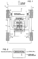
- Fig. 1 is a schematic block diagram showing a vehicle 1 mounted with a vehicle control apparatus.
- a vehicle 1 shown in Fig. 1 is a front-wheel-drive car, and is equipped with wheels 11a, 11b, 11c and 11d at front, rear, left and right of a vehicle, and the rotation driving force from a driving force generation apparatus 17, which is configured by, for example, a gasoline engine (electrically-driven motor etc. may be acceptable) or transmission etc. is designed to be transmitted to the front wheels 11a and 11b.
- a wheel speed sensor 12 for detecting rotation speed of the wheel (rotation number), and a break 18 are attached.
- a control unit 5 having a built-in microcomputer and built-in electronic circuit parts for carrying out the vehicle control is equipped as a main configuration element of a vehicle control apparatus 3 of the present embodiment, as well as a roll angular velocity sensor 14 is allocated.
- the built-in microcomputer in the control unit 5 is well known themselves, and equipped with CPU, ROM, RAM, IO and the like.
- the roll angular velocity sensor 14 is one for detecting the roll angular velocity p of the vehicle 1, and is configured, for example, by a gyro sensor.
- the control unit 5 is equipped with a vehicle speed calculation unit 13, where a wheal speed signal from a wheel speed sensor 12 attached at each of the wheels 11a, 11b, 11c and 11d is input, a lateral jerk calculation unit 15, where a roll angular velocity signal from the roll angular velocity sensor 14 is input, and a breaking and driving force control unit 16 for carrying out vehicle control (here, breaking control and driving force control) based on lateral jerk calculated from this lateral jerk calculation unit 15, as shown in a functional block diagram in Fig. 1 .
- the vehicle speed calculation unit 13 calculates a vehicle speed V, which is a speed in a travelling direction of the vehicle 1, based on rotation number of each of the wheels 11a, 11b, 11c and 11d detected by the wheel speed sensor 12.
- a vehicle speed V a speed in a travelling direction of the vehicle 1
- Va, Vb, Vc and Vd which are the speeds of each of the wheels 11a, 11b, 11c and 11d in a travelling direction, are calculated by multiplying the radius to angular velocity of each of the wheels 11a, 11b, 11c and 11d.
- the vehicle speed V may be an average value of Va, Vb, Vc and Vd, or may be the lowest value of Va, Vb, Vc and Vd, in consideration of spinning possibility of some of the wheels of 11a, 11b, 11c and 11d, or may be the second lowest value thereof, or average value of the lowest value and the second lowest value, or the like.
- the lateral jerk calculation unit 15 calculates (estimates) the lateral jerk Jy, based on the roll angular velocity p detected by the roll angular velocity sensor 14. The detail on this lateral jerk calculation unit 15 will be described later.
- the breaking and driving force control unit 16 calculates control command value for controlling a driving force generation unit 17 or the break 18, based on vehicle speed or lateral jerk Jy or the like. The detail on this breaking and driving force control unit 16 will be described later.
- the lateral jerk calculation unit 15 calculates, as shown in Fig. 2 , the lateral jerk Jy by using (a vehicle motion model 30 represented by) a transfer function A having the roll angular velocity p as input and the lateral jerk Jy as output.
- g gravity acceleration
- s Laplace operator
- Ix roll inertia moment
- Cx roll viscosity
- Kx roll rigidity
- J y s p s I x ⁇ s 2 + C x ⁇ s + K x - m s ⁇ gh m s ⁇ h
- the lateral jerk Jy may be calculated from the following Expression 2, by using relatively high frequency f (for example, 100 Hz).
- f for example, 100 Hz.
- Figs. 3A and 3B are graphs showing examples of frequency response characteristics of the transfer function A represented by the Expression 2, taking the frequency as abscissa axis, and the gain and the phase as ordinate axis, respectively.
- the transfer function A has the phase lead characteristics, and has the feature in calculating the lateral jerk Jy by a little advancing the phase of roll angular velocity p.
- T1 and T2 in the Expression 3 are set in advance so that the frequency response characteristics up to about 1 Hz becomes close to characteristics shown in Figs. 3A and 3B .
- Figs. 4A and 4B are graphs showing examples of frequency response characteristics of the transfer function A represented by the Expression 3. From Figs. 4A and 4B , it is understood that the phase lead characteristics is nearly the same as that shown in Figs. 3A and 3B , up to about 1 Hz.
- Figs. 5A to 5C show the cases according to a conventional method: Fig. 5A shows lateral acceleration sensor value in carrying out the lane change by a passenger car, and Fig. 5B shows value differentiated a signal of Fig. 5A , which is understood to have very large noise.
- a solid line of Fig. 5C shows a value (calculated value) of lateral jerk determined by passing the differentiated value of Fig. 5B through a low-pass filter, and a broken line of Fig. 5C shows a true value of lateral jerk.
- the calculated value shown by the solid line in Fig. 5C has a far delayed phase as compared with true value shown by the broken line, and it is understood that accuracy of lateral jerk determined by a conventional method is inferior.
- Figs. 6A and 6B are graphs showing the case according to the present embodiment used a transfer function A: Fig. 6A shows, similarly to Fig. 5A , a roll angular velocity sensor value in carrying out the lane change by a passenger car.
- a solid line of Fig. 6B shows a value (calculated value) of lateral jerk determined by passing the roll angular velocity value of Fig. 6A through the transfer function A having frequency response characteristics shown in Figs 4A and 4B , and a broken line of Fig. 6B shows true value of lateral jerk.
- the calculated value shown by the solid line in Fig. 6B is nearly coincident with true value shown by the broken line, and it is understood that accuracy of lateral jerk is good.
- the lateral jerk Jy is designed to be calculated by using the transfer function A having roll angular velocity p as input, therefore the lateral jerk having the good accuracy can be obtained.
- Fig. 7 is a functional block diagram showing a detailed configuration example of a breaking and driving force control unit 16 for carrying out breaking and driving force control by using the lateral jerk Jy calculated as explained above.
- the breaking and driving force control unit 16 is equipped with a driver request vehicle speed calculation unit 31, an upper limit vehicle speed calculation unit 32, and a breaking and driving force command value calculation unit 33.
- the driver request vehicle speed calculation unit 31 calculates the vehicle speed V1, which is expected in the case where the present breaking and driving force control is not carried out, from the present acceleration opening degree detected by an acceleration pedal sensor (not shown), and engine speed and transmission gear position in a driving force generation apparatus 17, by using a map set in advance based on experimental results.
- the upper limit vehicle speed calculation unit 32 calculates the upper limit value V2 of the present vehicle speed, which is necessary for stably travelling a curve, by detecting the curvature k of the curve in a travelling direction (in the case or an arc, the curvature k becomes an inverse number of radius) and distance L up to the curve, from a car navigation or a camera or the like (not shown).
- an upper limit vehicle speed V3 in a curve is calculated.
- the upper limit vehicle speed V3 in a curve brings the vehicle to upper limit vehicle speed, which is capable of travelling stably in the curve.
- the present upper limit vehicle speed V2 is calculated from upper limit vehicle speed V3 in a curve and distance L up to the curve, and it is output from an upper limit vehicle speed calculator 32.
- the present upper limit vehicle speed V2 brings the vehicle speed so as to decelerate smoothly before the curve.
- the present upper limit vehicle speed V2 may be calculated so as to decelerate while changing deceleration degree so as to make the absolute value of forward and afterward jerk small.
- V2 is each calculated based on curvature k at each position, and the smallest value among them is output from an upper limit vehicle speed calculation unit 32.
- the breaking and driving force command value calculation unit 33 outputs driving force command value for controlling the driving force generation apparatus 17, and braking command value for controlling the break 18.
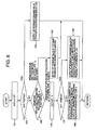
- Fig. 8 is a flow chart showing a control calculation example carried out by the breaking and driving force command value calculation unit 33 in the breaking and driving force control unit 16.
- a difference amount ⁇ V2 is obtained by subtracting the present upper limit vehicle speed V2 from the present vehicle speed V in the step 101, and in the next step 102, it is judged whether the difference amount ⁇ V2 is positive or not, and in the case of positive, it is forwarded to the step 103, and in the case of not positive, it is forwarded to the step 104.
- the step 103 outputs the breaking command value in response to the largeness of the difference amount ⁇ V2.
- the breaking command value is set to such value, for example, that provides the stronger breaking with the larger difference amount ⁇ V2.
- step 104 it is determined whether the break was applied before one cycle, and whether the lateral jerk Jy is near 0 or not. If the brake was applied before one cycle and the lateral jerk Jy is not near 0, it is forwarded to the step 105. If the brake was not applied before one cycle, or the lateral jerk Jy is near 0, it is forwarded to the step 106.
- the step 105 outputs the breaking command value having the same largeness of breaking force as in one cycle before. It should be noted that in this step 105, such command value may be output that the breaking force is gradually decreased from one cycle before.
- difference amount ⁇ V1 is obtained by subtracting the present vehicle speed V from driver request vehicle speed V1, and in the subsequent step 107, it is judged whether the difference amount ⁇ V1 is positive or not, and in the case of positive, it is forwarded to the step 108, and in the case of not positive, it is forwarded to the step 109.
- the step 108 outputs the breaking command value that the breaking force becomes 0, and the driving force command value in response to largeness of ⁇ V1.
- the driving force command value is set to such value, for example, that provides stronger driving force with the larger ⁇ V1.
- the step 109 outputs the breaking command value that the breaking force becomes 0, and the driving force command value that driving force becomes 0. It should be noted that, in this step 109, such command value may be output that the driving force is gradually decreased from one cycle before.
- Fig. 9 is a schematic block diagram showing a vehicle 1' where other embodiments of the vehicle control apparatus were applied.
- a vehicle 1' shown in Fig. 9 the same reference numbers are given to parts corresponding to each of parts of the vehicle 1 shown in Fig. 1 , to omit the duplicated explanation, and in the explanation below, different points will be provided mainly between the vehicle control apparatus 3' of the present embodiment and the vehicle control apparatus 3 of the above embodiment.
- a control unit 5' having a built-in microcomputer and electronic circuit parts for carrying out vehicle control is equipped as a main configuration element of a vehicle control apparatus 3' of the present embodiment, as well as the roll angular velocity sensor 14 is allocated.
- the control unit 5' is equipped with, as shown by a functional block diagram in Fig. 9 , a vehicle speed calculation unit 13, where a wheal speed signal from a wheel speed sensor 12 attached at each of the wheels 11a, 11b, 11c and 11d is input, and a lateral jerk calculation unit 15, where a roll angular velocity signal from the roll angular velocity sensor 14 is input, and a yaw moment control unit 19 for carrying out the vehicle control (here, yaw moment control) based on vehicle speed V and lateral jerk Jy or the like calculated by the vehicle speed calculation unit 13 and the lateral jerk calculation unit 15.
- vehicle speed calculation unit 13 where a wheal speed signal from a wheel speed sensor 12 attached at each of the wheels 11a, 11b, 11c and 11d is input
- a lateral jerk calculation unit 15 where a roll angular velocity signal from the roll angular velocity sensor 14 is input
- a yaw moment control unit 19 for carrying out the vehicle control (he
- the yaw moment control unit 19 calculates the control command value for controlling a yaw moment generation mechanism 20, which is built in the driving force generation apparatus 17', based on vehicle speed V or lateral jerk Jy or the like.
- the yaw moment generation mechanism 20 is a mechanism to generate yaw moment of the vehicle 1', by generating torque difference between a left rear wheel 1c and a right rear wheel 1d.
- JP-A-2007-139011 As for detail of the yaw moment generation mechanism, refer to, for example, JP-A-2007-139011 , if necessary.
- the yaw moment control unit 19 is equipped with a yaw angular acceleration calculation unit 41, which calculates a yaw angular acceleration dr by differentiating a value of yaw angular speed r detected by the yaw angular sensor (not shown), a target yaw angular acceleration calculation unit 42 and a yaw moment command value calculation unit 43.
- the yaw moment command value calculation unit 43 outputs the yaw moment command value for generating the yaw moment in a direction to make close value of yaw angular acceleration dr and the target yaw angular acceleration dr2. That is, the yaw moment control unit 19 carries out the control to make close the value obtained by dividing the lateral jerk Jy with vehicle speed V, and the value of yaw angular acceleration.
- the yaw moment is generated in a direction for promoting turning round in starting turning round, and yaw moment is generated in a direction for suppressing turning round in ending turning round, therefore, it is capable of significantly enhancing response property and convergence of vehicle movement, in other words, the quick and correct reaction can be obtained without generation of large blurring of a vehicle to steering of a driver.
- Fig. 11 shows the lateral jerk calculation unit 15' with different configuration from a lateral jerk calculation unit 15 of the above embodiment.
- This lateral jerk calculation unit 15' calculates the lateral jerk Jy by using (a vehicle motion model 50 expressed by) the transfer function B having steering angle ⁇ detected by a steering angle sensor (not shown) as input and the lateral acceleration as output.
- V represents vehicle speed
- s represents Laplace operator
- m vehicle weight
- Iz vehicle yaw inertia moment
- lf distance between centers of gravity of front axes
- lr distance between centers of gravity of rear axes
- Kf cornering power of front wheels
- Kr cornering power of rear wheels
- n steering gear ratio
- a y ⁇ ⁇ s ⁇ s 2 ⁇ I x ⁇ K f ⁇ Vs 2 + 4 ⁇ l ⁇ l r ⁇ K f ⁇ K r ⁇ s + 4 ⁇ l ⁇ K f ⁇ K r ⁇ V m ⁇ VI z ⁇ s 2 + 2 ⁇ m ⁇ l f 2 ⁇ K f + l r 2 ⁇ K r + 2 ⁇ I z ⁇ K f + K r ⁇ s + 4 ⁇ l 2 ⁇ K f ⁇ K r V - 2 ⁇
- Figs. 12A and 12B show examples of frequency response characteristics of the transfer function B represented by the Expression 4.
- the transfer function B is characterized in that characteristics thereof changes with vehicle speed V, and also has low-pass characteristics up to about 1 Hz.
- the transfer function B may be calculated by the following Expression 5 may be used, which is a simplified form of the Expression 4.
- Expression 5 is a simplified form of the Expression 4.
- T0 of the above Expression 5 is designed to be changed in response to vehicle speed V by using a map.
- the map is set in advance so that the frequency response characteristics up to about 1 Hz becomes close to characteristics shown in Figs. 12A and 12B .
- Figs. 13A and 13B show examples of frequency response characteristics of the transfer function B represented by the Expression 5. As shown in Figs. 13A and 13B , it is understood that it has low-pass characteristics up to about 1 Hz, nearly the same as in Figs 12A and 12B .
- An estimated lateral acceleration Ay' calculated by the transfer function B is processed by sequentially sending to a lateral acceleration limiting unit 52, a differentiation unit 53 and a low-pass filtering unit 54, which are equipped in a lateral jerk calculation unit 15', and is taken out as the lateral jerk Jy, as shown in Fig. 11 . That is, in the lateral acceleration limiting unit 52, it is limited to ⁇ ⁇ Ay of lateral acceleration Ay detected by a lateral acceleration sensor (not shown) ( ⁇ Ay is, for example, 1 m/sec 2 .).
- the lateral acceleration limiting unit 52 outputs (Ay + ⁇ Ay), when Ay' is larger than (Ay + ⁇ Ay); outputs (Ay - ⁇ Ay), when Ay' is smaller than (Ay - ⁇ Ay); and outputs Ay' when Ay' is none of these.
- Output of this lateral acceleration limiting unit 52 is differentiated in the differentiation unit 53, and the high frequency components of the value output from the differentiation unit 53 are removed in the subsequent low-pass filtering unit 54.
- the cut-off frequency of the low-pass filtering unit 54 is set so that noise is removed as much as possible, and set to frequency (for example, 3 Hz) not to give influence on control.
- the lateral acceleration limiting processing, differentiating processing and filtering processing are designed here to be carried out by a built-in microprocessor in the control unit 5, however, it may be designed to be carried out by other electronic circuit as its substitution.
- Fig. 14A shows steering angle sensor value in travelling similarly to in the case shown in Fig. 5 and Fig. 6 .
- the estimated lateral acceleration Ay' calculated by inputting this steering angle sensor value to the transfer function B, is shown by a solid line in Fig. 14B
- the lateral acceleration sensor value Ay is shown by a broken line in Fig. 14B .
- the estimated lateral acceleration Ay' shown by the solid line in Fig. 14B and the lateral acceleration sensor value Ay shown by the broken line Ay are nearly the same, and absolute value of difference between them is always within ⁇ Ay (1 m/s 2 ), therefore the output of the lateral acceleration limiting unit 52 is always the same as Ay'.
- FIG. 14C shows a signal obtained by differentiating the output of the lateral acceleration limiting unit 52 by the differentiation unit 53 and after passing it through the low-pass filtering unit 54, that is, shows a value (calculated value) of lateral jerk calculated by the lateral jerk calculation unit 15' of the present embodiment, and the broken line of Fig. 14C is true value of lateral jerk.
- the calculated value shown by the solid line in Fig. 14C is nearly coincident with true value shown by the broken line, and thus it is understood that the lateral jerk determined by the lateral jerk calculation unit 15' of the present embodiment has a good accuracy.
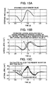
- Fig. 15A shows a steering angle sensor value in the case where the lane change was carried out so rapidly as a vehicle skids; a solid line of Fig. 15B shows the estimated lateral acceleration Ay' calculated by inputting a signal (steering angle sensor value) of Fig. 15A to the transfer function B; and a broken line of Fig. 15B is the lateral acceleration sensor value Ay.
- the estimated acceleration Ay' shown by the solid line of Fig. 15B and the lateral acceleration sensor value Ay shown by the broken line are far apart, and the output of lateral acceleration limiting unit 52 during that period becomes the lateral acceleration sensor value Ay, and the output of lateral acceleration limiting unit 52 during other than that period becomes the estimated lateral acceleration Ay'.
- the solid line of Fig. 15C shows a signal obtained by differentiating the output of lateral acceleration limiting unit 52 by the differentiation unit 53 and after passing it through the low-pass filtering unit 54, that is, shows the value (calculated value) of lateral jerk determined by the lateral jerk calculation unit 15' of the present embodiment, and the broken line of Fig. 15C is the true value of lateral jerk.
- the calculated value shown by the solid line in Fig. 15C is nearly coincident with true value shown by the broken line, and thus it is understood that the lateral jerk determined by the lateral jerk calculation unit 15' of the present embodiment has a good accuracy.
- the lateral jerk can be calculated with high accuracy.
- the control to end deceleration or start acceleration can be carried out adequately during a period when value of lateral jerk is near zero, and the control of acceleration and deceleration can be carried out without generation of uncomfortable feeling to a driver.
- the yaw moment can be generated in a direction for promoting turning round (revolving) in starting turning round (revolving), and yaw moment can be generated in a direction for suppressing turning round (revolving) in ending turning round (revolving), therefore, it is capable of significantly enhancing response property and convergence of vehicle movement.
Landscapes
- Engineering & Computer Science (AREA)
- Automation & Control Theory (AREA)
- Transportation (AREA)
- Mechanical Engineering (AREA)
- Physics & Mathematics (AREA)
- Mathematical Physics (AREA)
- Control Of Driving Devices And Active Controlling Of Vehicle (AREA)
- Regulating Braking Force (AREA)
- Vehicle Body Suspensions (AREA)
Applications Claiming Priority (1)
| Application Number | Priority Date | Filing Date | Title |
|---|---|---|---|
| JP2007280808A JP4997065B2 (ja) | 2007-10-29 | 2007-10-29 | 車両制御装置 |
Publications (3)
| Publication Number | Publication Date |
|---|---|
| EP2055600A2 true EP2055600A2 (de) | 2009-05-06 |
| EP2055600A3 EP2055600A3 (de) | 2009-06-24 |
| EP2055600B1 EP2055600B1 (de) | 2013-01-16 |
Family
ID=40280798
Family Applications (1)
| Application Number | Title | Priority Date | Filing Date |
|---|---|---|---|
| EP08018750A Not-in-force EP2055600B1 (de) | 2007-10-29 | 2008-10-27 | Fahrzeugsteuervorrichtung |
Country Status (3)
| Country | Link |
|---|---|
| US (1) | US7853366B2 (de) |
| EP (1) | EP2055600B1 (de) |
| JP (1) | JP4997065B2 (de) |
Families Citing this family (18)
| Publication number | Priority date | Publication date | Assignee | Title |
|---|---|---|---|---|
| JP5143103B2 (ja) * | 2009-09-30 | 2013-02-13 | 日立オートモティブシステムズ株式会社 | 車両の運動制御装置 |
| US8078359B2 (en) * | 2009-10-05 | 2011-12-13 | Tesla Motors, Inc. | User configurable vehicle user interface |
| US8818624B2 (en) * | 2009-10-05 | 2014-08-26 | Tesla Motors, Inc. | Adaptive soft buttons for a vehicle user interface |
| US20110082618A1 (en) * | 2009-10-05 | 2011-04-07 | Tesla Motors, Inc. | Adaptive Audible Feedback Cues for a Vehicle User Interface |
| US9079498B2 (en) * | 2009-10-05 | 2015-07-14 | Tesla Motors, Inc. | Morphing vehicle user interface |
| JP5414454B2 (ja) * | 2009-10-23 | 2014-02-12 | 日立オートモティブシステムズ株式会社 | 車両運動制御装置 |
| JP5690176B2 (ja) | 2011-03-11 | 2015-03-25 | 日立オートモティブシステムズ株式会社 | 慣性センサ |
| JP5764656B2 (ja) * | 2011-05-11 | 2015-08-19 | 日立オートモティブシステムズ株式会社 | 車両運動制御装置 |
| KR20130044727A (ko) * | 2011-10-24 | 2013-05-03 | 현대모비스 주식회사 | 전동식 동력 조향장치를 이용한 차륜 정렬장치의 요구명령 생성방법 |
| JP2014148182A (ja) * | 2013-01-31 | 2014-08-21 | Hitachi Automotive Systems Ltd | 車両の走行制御装置 |
| JP6229376B2 (ja) * | 2013-09-02 | 2017-11-15 | トヨタ自動車株式会社 | 車両運転状況判定装置及び車両運転状況判定方法 |
| CN104571100B (zh) * | 2015-01-28 | 2017-06-27 | 北京控制工程研究所 | 一种非最小相位高超声速飞行器控制方法 |
| JP2016182959A (ja) * | 2016-06-30 | 2016-10-20 | 日立オートモティブシステムズ株式会社 | 車両の運動制御装置 |
| US10919520B1 (en) | 2016-08-03 | 2021-02-16 | Apple Inc. | Integrated chassis control |
| DE112018002154T5 (de) | 2017-06-15 | 2020-01-09 | Hitachi Automotive Systems, Ltd. | Fahrzeugsteuervorrichtung |
| JP6568560B2 (ja) * | 2017-09-15 | 2019-08-28 | 株式会社Subaru | 車両の走行制御装置 |
| JP6506812B2 (ja) * | 2017-10-06 | 2019-04-24 | 日立オートモティブシステムズ株式会社 | 車両の運動制御装置、及び運動制御プログラム |
| JP7150001B2 (ja) * | 2020-12-28 | 2022-10-07 | 本田技研工業株式会社 | 車両制御装置 |
Citations (3)
| Publication number | Priority date | Publication date | Assignee | Title |
|---|---|---|---|---|
| JP2621390B2 (ja) | 1987-09-04 | 1997-06-18 | トヨタ自動車株式会社 | 電子制御サスペンション装置 |
| JP2007112367A (ja) | 2005-10-24 | 2007-05-10 | Hitachi Ltd | 車両タイヤ状態検出方法および車両タイヤ状態検出装置 |
| JP2007139011A (ja) | 2005-11-16 | 2007-06-07 | Hitachi Ltd | 車軸間トルク発生装置 |
Family Cites Families (54)
| Publication number | Priority date | Publication date | Assignee | Title |
|---|---|---|---|---|
| JP2594126B2 (ja) * | 1987-09-04 | 1997-03-26 | トヨタ自動車株式会社 | 電子制御サスペンション装置 |
| JP2623861B2 (ja) * | 1989-09-29 | 1997-06-25 | 日産自動車株式会社 | 能動型サスペンション |
| JP3017512B2 (ja) * | 1990-04-27 | 2000-03-13 | アイシン精機株式会社 | 車輌のロール制御装置 |
| JP3275320B2 (ja) * | 1991-04-25 | 2002-04-15 | トヨタ自動車株式会社 | 車輪のスリップ状態評価装置 |
| JP3015514B2 (ja) | 1991-06-26 | 2000-03-06 | ナルデック株式会社 | 車両のサスペンション装置 |
| JP3124633B2 (ja) * | 1992-08-05 | 2001-01-15 | 株式会社ユニシアジェックス | 車両懸架装置 |
| JP4003241B2 (ja) * | 1995-12-27 | 2007-11-07 | トヨタ自動車株式会社 | 車両用乗員姿勢補助装置 |
| US5895433A (en) * | 1996-05-23 | 1999-04-20 | General Motors Corporation | Vehicle chassis system control method and apparatus |
| JPH1178465A (ja) * | 1997-09-10 | 1999-03-23 | Nissan Motor Co Ltd | ロール剛性制御装置 |
| US6175792B1 (en) * | 1998-02-03 | 2001-01-16 | Trw Inc. | Apparatus and method for improving dynamic response of an active roll control vehicle suspension system |
| US6038495A (en) * | 1998-02-06 | 2000-03-14 | Delco Electronics Corporation | Vehicle rollover sensing using short-term integration |
| US6292759B1 (en) * | 1998-11-19 | 2001-09-18 | Delphi Technologies, Inc. | Vehicle attitude angle estimation using sensed signal blending |
| JP3608442B2 (ja) * | 1999-07-15 | 2005-01-12 | トヨタ自動車株式会社 | 車輌の減衰係数制御装置 |
| US6304805B1 (en) * | 1999-07-21 | 2001-10-16 | Denso Corporation | Vehicle behavior estimating and controlling method and system as well as body slip angle estimating method and system |
| US6438463B1 (en) * | 1999-09-06 | 2002-08-20 | Honda Giken Kogyo Kabushiki Kaisha | Process for determining lateral overturning of vehicle, and system for detecting inclination angle of vehicle body |
| US6834218B2 (en) * | 2001-11-05 | 2004-12-21 | Ford Global Technologies, Llc | Roll over stability control for an automotive vehicle |
| US6324446B1 (en) * | 1999-12-21 | 2001-11-27 | Ford Global Technologies, Inc. | Roll over stability control for an automotive vehicle |
| US6415215B1 (en) * | 2000-02-23 | 2002-07-02 | Koyo Seiko Co., Ltd. | Vehicle attitude control apparatus |
| US6282474B1 (en) * | 2000-06-04 | 2001-08-28 | Ford Global Technologies, Inc. | Method and apparatus for detecting rollover of an automotive vehicle |
| US7109856B2 (en) * | 2000-09-25 | 2006-09-19 | Ford Global Technologies, Llc | Wheel lifted and grounded identification for an automotive vehicle |
| US6356188B1 (en) * | 2000-09-25 | 2002-03-12 | Ford Global Technologies, Inc. | Wheel lift identification for an automotive vehicle |
| JP2002104149A (ja) * | 2000-09-29 | 2002-04-10 | Toyota Motor Corp | 車輪の回転状態検出装置 |
| US6477480B1 (en) * | 2000-11-15 | 2002-11-05 | Ford Global Technologies, Inc. | Method and apparatus for determining lateral velocity of a vehicle |
| US6584388B2 (en) * | 2001-11-08 | 2003-06-24 | Delphi Technologies, Inc. | Adaptive rollover detection apparatus and method |
| JP3736340B2 (ja) * | 2000-12-14 | 2006-01-18 | トヨタ自動車株式会社 | 車両制御装置 |
| JP3518509B2 (ja) * | 2000-12-28 | 2004-04-12 | トヨタ自動車株式会社 | ロールオーバ判定装置 |
| JP3788286B2 (ja) * | 2001-01-19 | 2006-06-21 | トヨタ自動車株式会社 | 乗員保護装置の制御装置 |
| US6644454B2 (en) * | 2001-01-23 | 2003-11-11 | Toyota Jidosha Kabushiki Kaisha | Running condition control system for vehicle and method |
| US6799092B2 (en) * | 2001-02-21 | 2004-09-28 | Ford Global Technologies, Llc | Rollover stability control for an automotive vehicle using rear wheel steering and brake control |
| JP3608050B2 (ja) * | 2001-07-24 | 2005-01-05 | トヨタ自動車株式会社 | ロールオーバ判別装置 |
| US7079928B2 (en) * | 2002-08-01 | 2006-07-18 | Ford Global Technologies, Llc | System and method for determining a wheel departure angle for a rollover control system with respect to road roll rate and loading misalignment |
| US20040024505A1 (en) * | 2002-08-05 | 2004-02-05 | Salib Albert Chenouda | System and method for operating a rollover control system in a transition to a rollover condition |
| US20040024504A1 (en) * | 2002-08-05 | 2004-02-05 | Salib Albert Chenouda | System and method for operating a rollover control system during an elevated condition |
| US6963797B2 (en) * | 2002-08-05 | 2005-11-08 | Ford Global Technologies, Llc | System and method for determining an amount of control for operating a rollover control system |
| JP4331953B2 (ja) * | 2003-02-12 | 2009-09-16 | 本田技研工業株式会社 | 車両用操舵制御装置 |
| US7245998B2 (en) * | 2003-02-25 | 2007-07-17 | Denso Corporation | Apparatus for detecting rollover of vehicle and apparatus for activating occupant protective device |
| JP4063107B2 (ja) * | 2003-03-04 | 2008-03-19 | 株式会社デンソー | 乗員保護装置の起動装置 |
| JP4427964B2 (ja) * | 2003-03-31 | 2010-03-10 | 株式会社アドヴィックス | 車両の制御装置 |
| US6789002B1 (en) * | 2003-05-19 | 2004-09-07 | Delphi Technologies, Inc. | Determination of vehicle payload condition |
| JP3890477B2 (ja) * | 2003-06-12 | 2007-03-07 | 日産自動車株式会社 | 車輌の横転判定方法及び車輌の横転判定装置 |
| JP4145741B2 (ja) * | 2003-07-03 | 2008-09-03 | 三菱電機株式会社 | 車両のロールオーバ判別装置および車両のロールオーバ判別方法 |
| JP4380257B2 (ja) * | 2003-07-30 | 2009-12-09 | 株式会社アドヴィックス | 車両の運動制御装置 |
| JP4073856B2 (ja) * | 2003-10-08 | 2008-04-09 | 三菱電機株式会社 | 車両のロールオーバ判定装置 |
| US7222007B2 (en) * | 2004-01-07 | 2007-05-22 | Ford Global Technologies, Llc | Attitude sensing system for an automotive vehicle relative to the road |
| JP4244811B2 (ja) * | 2004-01-16 | 2009-03-25 | 株式会社デンソー | 横転判定装置 |
| JP4421330B2 (ja) * | 2004-02-26 | 2010-02-24 | アイシン精機株式会社 | スタビライザ制御装置 |
| US7502675B2 (en) * | 2004-04-01 | 2009-03-10 | Delphi Technologies, Inc. | Feedforward control of motor vehicle roll angle |
| US7451032B2 (en) * | 2004-06-02 | 2008-11-11 | Ford Global Technologies, Llc | System and method for determining desired yaw rate and lateral velocity for use in a vehicle dynamic control system |
| US7191047B2 (en) * | 2004-09-27 | 2007-03-13 | Delphi Technologies, Inc. | Motor vehicle control using a dynamic feedforward approach |
| US7715965B2 (en) * | 2004-10-15 | 2010-05-11 | Ford Global Technologies | System and method for qualitatively determining vehicle loading conditions |
| JP4703219B2 (ja) * | 2005-03-04 | 2011-06-15 | 三菱電機株式会社 | 画像表示装置 |
| KR100651549B1 (ko) * | 2005-05-13 | 2007-02-28 | 삼성전자주식회사 | 이동체의 속력 측정 장치 및 방법 |
| US7788007B2 (en) * | 2006-01-12 | 2010-08-31 | Gm Global Technology Operations, Inc. | Roll stability indicator for vehicle rollover control |
| JP4724593B2 (ja) | 2006-04-27 | 2011-07-13 | 日立オートモティブシステムズ株式会社 | 車両の運動制御装置 |
-
2007
- 2007-10-29 JP JP2007280808A patent/JP4997065B2/ja active Active
-
2008
- 2008-10-27 EP EP08018750A patent/EP2055600B1/de not_active Not-in-force
- 2008-10-28 US US12/259,948 patent/US7853366B2/en not_active Expired - Fee Related
Patent Citations (3)
| Publication number | Priority date | Publication date | Assignee | Title |
|---|---|---|---|---|
| JP2621390B2 (ja) | 1987-09-04 | 1997-06-18 | トヨタ自動車株式会社 | 電子制御サスペンション装置 |
| JP2007112367A (ja) | 2005-10-24 | 2007-05-10 | Hitachi Ltd | 車両タイヤ状態検出方法および車両タイヤ状態検出装置 |
| JP2007139011A (ja) | 2005-11-16 | 2007-06-07 | Hitachi Ltd | 車軸間トルク発生装置 |
Also Published As
| Publication number | Publication date |
|---|---|
| US20090112404A1 (en) | 2009-04-30 |
| EP2055600A3 (de) | 2009-06-24 |
| JP2009107447A (ja) | 2009-05-21 |
| JP4997065B2 (ja) | 2012-08-08 |
| US7853366B2 (en) | 2010-12-14 |
| EP2055600B1 (de) | 2013-01-16 |
Similar Documents
| Publication | Publication Date | Title |
|---|---|---|
| US7853366B2 (en) | Vehicle control apparatus | |
| JP4161923B2 (ja) | 車両安定化制御システム | |
| US8180525B2 (en) | Method and system for assisting a driver when parking or maneuvering a motor vehicle | |
| EP2433840B1 (de) | Bewegungssteuereinheit für ein Fahrzeug basierend auf Ruckinformation | |
| JP6396213B2 (ja) | ステアリング装置のラック力を決定するための方法、及び、ステアリング装置 | |
| JP3946294B2 (ja) | 制動力制御装置 | |
| EP2799822B1 (de) | Verfahren und vorrichtung zur schätzung des ladungszustandes eines fahrzeugs | |
| US9662974B2 (en) | Torque control for vehicles with independent front and rear propulsion systems | |
| US20150006034A1 (en) | Vehicle control device | |
| JP2009096349A (ja) | 車両用運転支援装置 | |
| US9914453B2 (en) | Method for predicting the travel path of a motor vehicle and prediction apparatus | |
| CN101652284A (zh) | 交通工具驾驶辅助 | |
| KR102164606B1 (ko) | 자율주행 차량을 위한 횡방향 제어 파라미터 보정 장치 및 방법 | |
| JP2008537707A (ja) | 車両の姿勢安定制御方法及びその装置 | |
| US20260109354A1 (en) | Control device for vehicle | |
| US20150094911A1 (en) | Device and method for determining the driving state of a vehicle | |
| JP4277907B2 (ja) | 自動車の走行制御装置 | |
| JP2000292316A (ja) | 車両の重心高さの推定演算装置 | |
| JP3443846B2 (ja) | 運転感覚制御装置 | |
| US20220227338A1 (en) | Vehicle control system | |
| JP3271956B2 (ja) | 車両の路面摩擦係数推定装置 | |
| KR20220011580A (ko) | 전방에 위치한 커브를 통과할 시 자기차량의 차량운전자를 지원하기 위한 방법 | |
| JP2008260439A (ja) | 車両挙動制御装置及び車両挙動制御方法 | |
| JP3645099B2 (ja) | 車両の重心移動速度推定演算装置 | |
| JP4928221B2 (ja) | 車両挙動制御装置 |
Legal Events
| Date | Code | Title | Description |
|---|---|---|---|
| PUAI | Public reference made under article 153(3) epc to a published international application that has entered the european phase |
Free format text: ORIGINAL CODE: 0009012 |
|
| AK | Designated contracting states |
Kind code of ref document: A2 Designated state(s): AT BE BG CH CY CZ DE DK EE ES FI FR GB GR HR HU IE IS IT LI LT LU LV MC MT NL NO PL PT RO SE SI SK TR |
|
| AX | Request for extension of the european patent |
Extension state: AL BA MK RS |
|
| PUAL | Search report despatched |
Free format text: ORIGINAL CODE: 0009013 |
|
| 17P | Request for examination filed |
Effective date: 20090424 |
|
| AK | Designated contracting states |
Kind code of ref document: A3 Designated state(s): AT BE BG CH CY CZ DE DK EE ES FI FR GB GR HR HU IE IS IT LI LT LU LV MC MT NL NO PL PT RO SE SI SK TR |
|
| AX | Request for extension of the european patent |
Extension state: AL BA MK RS |
|
| 17Q | First examination report despatched |
Effective date: 20091118 |
|
| AKX | Designation fees paid |
Designated state(s): DE FR GB IT |
|
| GRAP | Despatch of communication of intention to grant a patent |
Free format text: ORIGINAL CODE: EPIDOSNIGR1 |
|
| GRAS | Grant fee paid |
Free format text: ORIGINAL CODE: EPIDOSNIGR3 |
|
| GRAA | (expected) grant |
Free format text: ORIGINAL CODE: 0009210 |
|
| AK | Designated contracting states |
Kind code of ref document: B1 Designated state(s): DE FR GB IT |
|
| REG | Reference to a national code |
Ref country code: GB Ref legal event code: FG4D |
|
| REG | Reference to a national code |
Ref country code: DE Ref legal event code: R082 Ref document number: 602008021663 Country of ref document: DE Representative=s name: MERH-IP MATIAS ERNY REICHL HOFFMANN PATENTANWA, DE Ref country code: DE Ref legal event code: R082 Ref document number: 602008021663 Country of ref document: DE Representative=s name: MERH-IP MATIAS ERNY REICHL HOFFMANN, DE |
|
| REG | Reference to a national code |
Ref country code: DE Ref legal event code: R096 Ref document number: 602008021663 Country of ref document: DE Effective date: 20130307 |
|
| PLBE | No opposition filed within time limit |
Free format text: ORIGINAL CODE: 0009261 |
|
| STAA | Information on the status of an ep patent application or granted ep patent |
Free format text: STATUS: NO OPPOSITION FILED WITHIN TIME LIMIT |
|
| 26N | No opposition filed |
Effective date: 20131017 |
|
| PG25 | Lapsed in a contracting state [announced via postgrant information from national office to epo] |
Ref country code: IT Free format text: LAPSE BECAUSE OF FAILURE TO SUBMIT A TRANSLATION OF THE DESCRIPTION OR TO PAY THE FEE WITHIN THE PRESCRIBED TIME-LIMIT Effective date: 20130116 |
|
| REG | Reference to a national code |
Ref country code: DE Ref legal event code: R097 Ref document number: 602008021663 Country of ref document: DE Effective date: 20131017 |
|
| GBPC | Gb: european patent ceased through non-payment of renewal fee |
Effective date: 20131027 |
|
| PG25 | Lapsed in a contracting state [announced via postgrant information from national office to epo] |
Ref country code: GB Free format text: LAPSE BECAUSE OF NON-PAYMENT OF DUE FEES Effective date: 20131027 |
|
| PGFP | Annual fee paid to national office [announced via postgrant information from national office to epo] |
Ref country code: FR Payment date: 20141008 Year of fee payment: 7 Ref country code: DE Payment date: 20141023 Year of fee payment: 7 |
|
| REG | Reference to a national code |
Ref country code: DE Ref legal event code: R119 Ref document number: 602008021663 Country of ref document: DE |
|
| PG25 | Lapsed in a contracting state [announced via postgrant information from national office to epo] |
Ref country code: DE Free format text: LAPSE BECAUSE OF NON-PAYMENT OF DUE FEES Effective date: 20160503 |
|
| REG | Reference to a national code |
Ref country code: FR Ref legal event code: ST Effective date: 20160630 |
|
| PG25 | Lapsed in a contracting state [announced via postgrant information from national office to epo] |
Ref country code: FR Free format text: LAPSE BECAUSE OF NON-PAYMENT OF DUE FEES Effective date: 20151102 |