EP2055627A2 - Procédé destiné à la fabrication d'une coque d'un appareil de sport nautique - Google Patents
Procédé destiné à la fabrication d'une coque d'un appareil de sport nautique Download PDFInfo
- Publication number
- EP2055627A2 EP2055627A2 EP08170113A EP08170113A EP2055627A2 EP 2055627 A2 EP2055627 A2 EP 2055627A2 EP 08170113 A EP08170113 A EP 08170113A EP 08170113 A EP08170113 A EP 08170113A EP 2055627 A2 EP2055627 A2 EP 2055627A2
- Authority
- EP
- European Patent Office
- Prior art keywords
- hull
- boat body
- frame
- molding process
- blow
- Prior art date
- Legal status (The legal status is an assumption and is not a legal conclusion. Google has not performed a legal analysis and makes no representation as to the accuracy of the status listed.)
- Ceased
Links
- 238000004519 manufacturing process Methods 0.000 title claims abstract description 5
- XLYOFNOQVPJJNP-UHFFFAOYSA-N water Substances O XLYOFNOQVPJJNP-UHFFFAOYSA-N 0.000 title claims description 16
- 238000000034 method Methods 0.000 claims description 35
- 238000000071 blow moulding Methods 0.000 claims description 11
- 239000000463 material Substances 0.000 claims description 11
- 238000000465 moulding Methods 0.000 claims description 10
- 238000009757 thermoplastic moulding Methods 0.000 claims description 6
- 239000004698 Polyethylene Substances 0.000 claims description 3
- -1 polyethylene Polymers 0.000 claims description 3
- 229920000573 polyethylene Polymers 0.000 claims description 3
- 239000012815 thermoplastic material Substances 0.000 claims description 3
- 238000003856 thermoforming Methods 0.000 claims 1
- 239000007921 spray Substances 0.000 abstract description 4
- 229920001169 thermoplastic Polymers 0.000 abstract description 2
- 239000004416 thermosoftening plastic Substances 0.000 abstract description 2
- 238000007493 shaping process Methods 0.000 abstract 2
- 238000007664 blowing Methods 0.000 description 6
- 238000001746 injection moulding Methods 0.000 description 4
- 238000003825 pressing Methods 0.000 description 4
- 238000001175 rotational moulding Methods 0.000 description 3
- 239000005060 rubber Substances 0.000 description 3
- 238000003466 welding Methods 0.000 description 3
- 238000001125 extrusion Methods 0.000 description 2
- 230000004927 fusion Effects 0.000 description 2
- 230000012447 hatching Effects 0.000 description 2
- 238000012986 modification Methods 0.000 description 2
- 230000004048 modification Effects 0.000 description 2
- 239000000853 adhesive Substances 0.000 description 1
- 230000001070 adhesive effect Effects 0.000 description 1
- 230000015572 biosynthetic process Effects 0.000 description 1
- 239000011248 coating agent Substances 0.000 description 1
- 238000000576 coating method Methods 0.000 description 1
- 238000011109 contamination Methods 0.000 description 1
- 238000005520 cutting process Methods 0.000 description 1
- 230000001419 dependent effect Effects 0.000 description 1
- 238000011161 development Methods 0.000 description 1
- 230000018109 developmental process Effects 0.000 description 1
- 238000004090 dissolution Methods 0.000 description 1
- 230000008030 elimination Effects 0.000 description 1
- 238000003379 elimination reaction Methods 0.000 description 1
- 238000005304 joining Methods 0.000 description 1
- 238000010309 melting process Methods 0.000 description 1
- 239000002991 molded plastic Substances 0.000 description 1
- 239000002245 particle Substances 0.000 description 1
- 239000004033 plastic Substances 0.000 description 1
- 229920003023 plastic Polymers 0.000 description 1
- 238000010106 rotational casting Methods 0.000 description 1
- 238000007789 sealing Methods 0.000 description 1
- 239000007787 solid Substances 0.000 description 1
Images




Classifications
-
- B—PERFORMING OPERATIONS; TRANSPORTING
- B63—SHIPS OR OTHER WATERBORNE VESSELS; RELATED EQUIPMENT
- B63B—SHIPS OR OTHER WATERBORNE VESSELS; EQUIPMENT FOR SHIPPING
- B63B5/00—Hulls characterised by their construction of non-metallic material
- B63B5/24—Hulls characterised by their construction of non-metallic material made predominantly of plastics
-
- B—PERFORMING OPERATIONS; TRANSPORTING
- B29—WORKING OF PLASTICS; WORKING OF SUBSTANCES IN A PLASTIC STATE IN GENERAL
- B29C—SHAPING OR JOINING OF PLASTICS; SHAPING OF MATERIAL IN A PLASTIC STATE, NOT OTHERWISE PROVIDED FOR; AFTER-TREATMENT OF THE SHAPED PRODUCTS, e.g. REPAIRING
- B29C49/00—Blow-moulding, i.e. blowing a preform or parison to a desired shape within a mould; Apparatus therefor
- B29C49/02—Combined blow-moulding and manufacture of the preform or the parison
- B29C49/04—Extrusion blow-moulding
-
- B—PERFORMING OPERATIONS; TRANSPORTING
- B29—WORKING OF PLASTICS; WORKING OF SUBSTANCES IN A PLASTIC STATE IN GENERAL
- B29C—SHAPING OR JOINING OF PLASTICS; SHAPING OF MATERIAL IN A PLASTIC STATE, NOT OTHERWISE PROVIDED FOR; AFTER-TREATMENT OF THE SHAPED PRODUCTS, e.g. REPAIRING
- B29C49/00—Blow-moulding, i.e. blowing a preform or parison to a desired shape within a mould; Apparatus therefor
- B29C49/20—Blow-moulding, i.e. blowing a preform or parison to a desired shape within a mould; Apparatus therefor of articles having inserts or reinforcements ; Handling of inserts or reinforcements
-
- B—PERFORMING OPERATIONS; TRANSPORTING
- B29—WORKING OF PLASTICS; WORKING OF SUBSTANCES IN A PLASTIC STATE IN GENERAL
- B29C—SHAPING OR JOINING OF PLASTICS; SHAPING OF MATERIAL IN A PLASTIC STATE, NOT OTHERWISE PROVIDED FOR; AFTER-TREATMENT OF THE SHAPED PRODUCTS, e.g. REPAIRING
- B29C49/00—Blow-moulding, i.e. blowing a preform or parison to a desired shape within a mould; Apparatus therefor
- B29C49/22—Blow-moulding, i.e. blowing a preform or parison to a desired shape within a mould; Apparatus therefor using multilayered preforms or parisons
-
- B—PERFORMING OPERATIONS; TRANSPORTING
- B29—WORKING OF PLASTICS; WORKING OF SUBSTANCES IN A PLASTIC STATE IN GENERAL
- B29C—SHAPING OR JOINING OF PLASTICS; SHAPING OF MATERIAL IN A PLASTIC STATE, NOT OTHERWISE PROVIDED FOR; AFTER-TREATMENT OF THE SHAPED PRODUCTS, e.g. REPAIRING
- B29C51/00—Shaping by thermoforming, i.e. shaping sheets or sheet like preforms after heating, e.g. shaping sheets in matched moulds or by deep-drawing; Apparatus therefor
- B29C51/12—Shaping by thermoforming, i.e. shaping sheets or sheet like preforms after heating, e.g. shaping sheets in matched moulds or by deep-drawing; Apparatus therefor of articles having inserts or reinforcements
-
- B—PERFORMING OPERATIONS; TRANSPORTING
- B63—SHIPS OR OTHER WATERBORNE VESSELS; RELATED EQUIPMENT
- B63B—SHIPS OR OTHER WATERBORNE VESSELS; EQUIPMENT FOR SHIPPING
- B63B73/00—Building or assembling vessels or marine structures, e.g. hulls or offshore platforms
- B63B73/40—Building or assembling vessels or marine structures, e.g. hulls or offshore platforms characterised by joining methods
-
- B—PERFORMING OPERATIONS; TRANSPORTING
- B63—SHIPS OR OTHER WATERBORNE VESSELS; RELATED EQUIPMENT
- B63B—SHIPS OR OTHER WATERBORNE VESSELS; EQUIPMENT FOR SHIPPING
- B63B73/00—Building or assembling vessels or marine structures, e.g. hulls or offshore platforms
- B63B73/70—Building or assembling vessels or marine structures, e.g. hulls or offshore platforms characterised by using moulds; Moulds or plugs therefor
- B63B73/72—Building or assembling vessels or marine structures, e.g. hulls or offshore platforms characterised by using moulds; Moulds or plugs therefor characterised by plastic moulding, e.g. injection moulding, extrusion moulding or blow moulding
-
- B—PERFORMING OPERATIONS; TRANSPORTING
- B29—WORKING OF PLASTICS; WORKING OF SUBSTANCES IN A PLASTIC STATE IN GENERAL
- B29C—SHAPING OR JOINING OF PLASTICS; SHAPING OF MATERIAL IN A PLASTIC STATE, NOT OTHERWISE PROVIDED FOR; AFTER-TREATMENT OF THE SHAPED PRODUCTS, e.g. REPAIRING
- B29C49/00—Blow-moulding, i.e. blowing a preform or parison to a desired shape within a mould; Apparatus therefor
- B29C49/20—Blow-moulding, i.e. blowing a preform or parison to a desired shape within a mould; Apparatus therefor of articles having inserts or reinforcements ; Handling of inserts or reinforcements
- B29C2049/2017—Blow-moulding, i.e. blowing a preform or parison to a desired shape within a mould; Apparatus therefor of articles having inserts or reinforcements ; Handling of inserts or reinforcements outside the article
-
- B—PERFORMING OPERATIONS; TRANSPORTING
- B29—WORKING OF PLASTICS; WORKING OF SUBSTANCES IN A PLASTIC STATE IN GENERAL
- B29C—SHAPING OR JOINING OF PLASTICS; SHAPING OF MATERIAL IN A PLASTIC STATE, NOT OTHERWISE PROVIDED FOR; AFTER-TREATMENT OF THE SHAPED PRODUCTS, e.g. REPAIRING
- B29C49/00—Blow-moulding, i.e. blowing a preform or parison to a desired shape within a mould; Apparatus therefor
- B29C49/20—Blow-moulding, i.e. blowing a preform or parison to a desired shape within a mould; Apparatus therefor of articles having inserts or reinforcements ; Handling of inserts or reinforcements
- B29C2049/2021—Inserts characterised by the material or type
- B29C2049/2069—Inserts characterised by the material or type moulded in combination, e.g. injection moulded in the same mould before or after blow-moulding
-
- B—PERFORMING OPERATIONS; TRANSPORTING
- B29—WORKING OF PLASTICS; WORKING OF SUBSTANCES IN A PLASTIC STATE IN GENERAL
- B29C—SHAPING OR JOINING OF PLASTICS; SHAPING OF MATERIAL IN A PLASTIC STATE, NOT OTHERWISE PROVIDED FOR; AFTER-TREATMENT OF THE SHAPED PRODUCTS, e.g. REPAIRING
- B29C49/00—Blow-moulding, i.e. blowing a preform or parison to a desired shape within a mould; Apparatus therefor
- B29C49/20—Blow-moulding, i.e. blowing a preform or parison to a desired shape within a mould; Apparatus therefor of articles having inserts or reinforcements ; Handling of inserts or reinforcements
- B29C2049/2095—Means for preparing or treating the inserts, e.g. cutting, deforming, heating, cooling or applying adhesives
-
- B—PERFORMING OPERATIONS; TRANSPORTING
- B29—WORKING OF PLASTICS; WORKING OF SUBSTANCES IN A PLASTIC STATE IN GENERAL
- B29K—INDEXING SCHEME ASSOCIATED WITH SUBCLASSES B29B, B29C OR B29D, RELATING TO MOULDING MATERIALS OR TO MATERIALS FOR MOULDS, REINFORCEMENTS, FILLERS OR PREFORMED PARTS, e.g. INSERTS
- B29K2023/00—Use of polyalkenes or derivatives thereof as moulding material
- B29K2023/04—Polymers of ethylene
- B29K2023/06—PE, i.e. polyethylene
-
- B—PERFORMING OPERATIONS; TRANSPORTING
- B29—WORKING OF PLASTICS; WORKING OF SUBSTANCES IN A PLASTIC STATE IN GENERAL
- B29L—INDEXING SCHEME ASSOCIATED WITH SUBCLASS B29C, RELATING TO PARTICULAR ARTICLES
- B29L2031/00—Other particular articles
- B29L2031/30—Vehicles, e.g. ships or aircraft, or body parts thereof
- B29L2031/3067—Ships
- B29L2031/307—Hulls
-
- B—PERFORMING OPERATIONS; TRANSPORTING
- B63—SHIPS OR OTHER WATERBORNE VESSELS; RELATED EQUIPMENT
- B63B—SHIPS OR OTHER WATERBORNE VESSELS; EQUIPMENT FOR SHIPPING
- B63B34/00—Vessels specially adapted for water sports or leisure; Body-supporting devices specially adapted for water sports or leisure
- B63B34/20—Canoes, kayaks or the like
- B63B34/21—Canoes, kayaks or the like characterised by constructional features
Definitions
- the invention relates to a method and an apparatus for producing a hull of a water sports device.
- the hull is made by means of a thermoplastic molding process.
- the invention relates to a water sports device.
- thermoplastic molding techniques such as e.g. by means of a blow-molding process, a rotational molding process, a twin-sheet molding process or a deep-drawing molding process, made from thermoplastics.
- a blow-molding process for example, has the advantage over a rotational molding process that it can be carried out more cost-effectively and that better material properties of the blow-molded element produced can be achieved with the aid of the blow-molding process.
- openings and areas around openings can not be arbitrarily shaped. As a result, special requirements can not always be met satisfactorily.
- thermoplastically shaped hulls due to the substantially uniform wall thickness of thermoplastically shaped hulls no arbitrarily stable areas can be formed in the hull.
- areas in which a relatively large force is introduced into the hull, be reworked by in particular additional material is subsequently welded to the hull or other elements are attached in these areas.
- Such claimed areas are, in particular, handles provided in the hull or openings provided in the hull for securing a tow. In other areas where instability in general does not immediately result in damage to the hull, this instability is often accepted for cost reasons.
- a Süllrand is provided around the manhole around where then a spray ceiling is attached. This sill edge is either reinforced by attaching profiles or deliberately left unstable. In an unstable Süllrand but slipping of the spray ceiling is not reliably prevented. Furthermore, additional moldings for attaching a back support and for realizing leg supports must be retrofitted and attached.
- document US 4,980,112 shows a method according to the preamble of claim 1.
- document US 5,275,121 describes the manufacture of a boat with a flexible outer skin using a rotational casting process.
- the object of the invention is to provide a method and a device by which a hull of a water sports equipment is already largely completely produced in a thermoplastic molding process and only relatively minor reworking to complete the hull are required.
- a two-tone hull of a water sports equipment can be produced in a simple manner. There is no need to work on connecting an upper boat body part and a separate lower boat body part. The elimination of a joint between the upper and the lower part of the boat body possible leaks are avoided. Furthermore, a bicolor hull with the aid of the method according to the invention is simple, fast and inexpensive to produce. A subsequent coating the hull of the boat for color design is no longer essential.
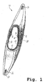
- Fig. 1 an inventive hull 10 of a canoe is shown, which is made of thermoplastic material in a blow molding process.
- the hull 10 has a Süllrahmen 12 with molded Schenkelab nulementen 14, 16, with integrally formed Wegver einsan füren 18, 20 and with a Süllrahmen 12 integrated arrangement for back support fixation 22.
- transport handles 24, 26 and a receiving opening 28 are provided for a Lenzstopfen in the hull 10.
- Both the grip element 24, the grip element 26 formed integrally with the bung plug opening 28 and the bale frame 12 have already been arranged in the blow mold before the blowing process.
- depressions are provided in the blow mold, in which the grip element 24, the coaming frame 12 and the grip element 26 are inserted with the Lenzstopfenö réelle 28.
- these inserted into the opening elements 12, 24, 26 are fixed there by suitable means.
- These inserted elements 12, 24, 26 are preferably preheated in the blow mold before the blowing process. Subsequently, a preform is introduced into the blow mold and inflated, so that forms on the inner wall of the blow mold or to the inserted into the blow mold elements 12, 24, 26 around a substantially uniformly strong blow-molded plastic layer.
- the blow-molded element touches at least a portion of the surface of the elements 12, 24, 26, whereby at least these contacted surface regions of these elements 12, 24, 26 are bonded to the blow-molded part formed by the blow-molding process, preferably by fusion bonding.
- This melting process is favored in particular by the preheating of the inserted elements 12, 24, 26.
- preheating the degree of fusion between the blow-molded element and the in the blow mold inserted elements 12, 24, 26 can be adjusted.
- the coaming frame 12 is arranged around an entry opening 30 of the hull 10 around, with a lateral circumferential groove 36 is provided in the coaming frame 12, which in the in FIG. 6 shown sectional view of the Süllrahmens 12 is shown.
- a circumferential spray cover which is also referred to as a cover, can be inserted and secured for sealing the access opening 30 to a protruding from the manhole 30 body of a person.
- the cover is tubular, with a hose end held in the groove 36 by means of a biased rubber ring.
- a further prestressed rubber ring may be provided which presses this end of the hose against the body projecting out of the manhole opening 30 and thereby seals it to the body.
- the projection formed above the groove 36 is also referred to as Süllrand.
- the profile of the Süllrahmens 12 is in the so-called extrusion-pressing method and the handle members 24, 26 are made by injection molding.
- the Süllrahmen 12 and the elements 24, 26 are preferably made of the same thermoplastic material as the hull 10, for example, a polyethylene material.
- the Süllrahmen 12 is preferably formed as a solid profile, whereby a high rigidity in the area around the manhole 30 is achieved around.
- the extrusion pressing method further enables other elements, such as the leg support elements 14, 16, the seat adjustment elements 18, 20 and the backrest fixing element 22, are formed directly on or in Süllrahmen 12.
- these elements 14 to 22 must be made consuming as individual parts and individually mounted in relatively complex manufacturing process on the blow molded hull 10.
- the joining of such elements 14 to 22 with the hull 10 is problematic because in particular the hull 10 by the introduction of fasteners such as screws or rivets, by the dissolution of the hull 10 with adhesive or the material changes in the subsequent welding of the hull 10 with the other elements 14 to 22 can be damaged.
- the method according to the invention for producing the hull 10 is substantially less expensive, whereby the quality of the hull 10 and the performance characteristics of the complete boat are substantially improved.
- a lance opening which is preferably provided at one end of the hull 10.
- the lance opening 28 is a simple removal of water present in the hull 10 water is possible.
- the ends of suitable hull shapes are usually difficult to access because these ends are tapered.
- the grip element 26 is produced together with the lance opening 28 as a component by injection molding.
- this component is inserted into the blow mold before the blowing process, whereby also this component is melted during the blowing process with the blow molding and thus welded.
- FIG. 2 is a side view of the hull 10 after Fig. 1 shown. Like elements have the same reference numerals.
- a sectional view of the in Fig. 2 with a circle bordered area is in Fig. 3 shown in detail in an enlarged sectional view.
- the blowing body manufactured in the blow molding process is in Fig. 3 shown with a hatching from top left to bottom right and the injection-molded component with the handle member 26 and the lance opening 28 is shown with a hatching from bottom left to top right.
- the injection-molded component has undercut areas 32, 34, which are enclosed by the blow body, so that in addition to or alternatively to the welding of the blow body with the injection-molded component, a positive connection is made.
- the injection-molded component with the grip element 26 and the Lenzstopfenö réelle 28 is thus both materially connected by the welding of the blow-molded element with the injection-molded element as well as by a positive connection by the engagement of the blow-molded element in the undercut areas 32, 34.
- a baffle 29 is provided in the strake plug opening 28, through which the baffle plug opening 28 is sealed.
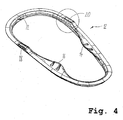
- Fig. 4 is a perspective top view of the underside of the Süllrahmens 12 shown.
- the Süllrahmen 12 forms a stable frame around the manhole 30, which stabilizes the hull 10 around the manhole 30 around.
- the backrest fixation element 22, the seat adjustment elements 18, 20 and the leg support elements 14, 16 are in Fig. 4 shown in more detail.
- Fig. 5 is a detailed account of the in Fig. 4 represented by the circle enclosed area of Süllrahmens 12.
- the formation of the seat adjustment member 18 on Süllrahmen 12 shown in detail are visible in the wells that serve as a grid for positioning and securing a seat.
- Fig. 6 is a sectional view of the Süllrahmens 12 by the sectional plane AA after Fig. 5 represented by the Süllrahmen formed seat adjustment member 18 therethrough.
- the Süllrahmen 12 has a laterally encircling groove 36, in which, as already mentioned a circumferential Schwitzbergpersenning can intervene.
- the cover can also be secured by means of a lacing from sliding out of the groove 36.
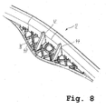
- Fig. 7 is a perspective view of the top of the Süllrahmens 12 is shown.
- Fig. 8 is the in Fig. 7 marked by means of a circle area of Süllrahmens 12 shown in an enlarged view.
- This region comprises the leg support element 16.
- the leg support elements 14, 16 have stiffening elements arranged in the manner of a grid at the top, two of which are designated by the reference numerals 38, 40. Further, further stiffening elements 42, 44 are provided, which prevent kinking of the Süllrahmen 12 inwardly to the manhole 30 projecting toward Schenkelab spalementes 16 even with a relatively large force.
- the blow-molded hull 10 is made from at least a two-layer preform, wherein the first layer of the preform contains a material of a first color and the second layer contains a material of a second color.
- a preform and a method and an apparatus for producing such a at least two-layer preform is known from the document DE 195 45 441 A1 known.
- the embodiments of the preform and method and apparatus for making such a preform contained in this document are hereby incorporated by reference into the present specification.
- the at least two-layer preform is introduced into the blow mold such that the hull 10 after the blowing process, at least the outer layer of the upper part of the hull 10 has the first color and at least the outer layer of the lower part of the hull 10 has the second color.
- the color design of the water sports equipment is crucial for the purchase and popularity of a water sports equipment, so that a two-tone design of the hull 10 is very advantageous for the customer interest and thus for the sale of the water sports equipment.
- the outer layer of the lower part of the hull 10 in a dark color and the upper part of the hull 10 in a light color since the light color absorbs the sun's rays only slightly. Contaminations with particles present in the water, which are deposited over a longer period of time on the lower part of the hull 10 located in the water, on the other hand, are not so visible on a dark surface.
- thermoplastic molding processes may be used to form a thermoplastic-molded element according to the invention and at least one further element, such as e.g. a rotational molding method, a twin-sheet molding method or a deep-drawing molding method.
Landscapes
- Engineering & Computer Science (AREA)
- Mechanical Engineering (AREA)
- Chemical & Material Sciences (AREA)
- Combustion & Propulsion (AREA)
- Ocean & Marine Engineering (AREA)
- Manufacturing & Machinery (AREA)
- Architecture (AREA)
- Structural Engineering (AREA)
- Blow-Moulding Or Thermoforming Of Plastics Or The Like (AREA)
- Moulds For Moulding Plastics Or The Like (AREA)
- Moulding By Coating Moulds (AREA)
- Ceramic Products (AREA)
- Separation Using Semi-Permeable Membranes (AREA)
- Electrical Discharge Machining, Electrochemical Machining, And Combined Machining (AREA)
- Golf Clubs (AREA)
Applications Claiming Priority (2)
| Application Number | Priority Date | Filing Date | Title |
|---|---|---|---|
| DE102004063561A DE102004063561A1 (de) | 2004-12-30 | 2004-12-30 | Verfahren und Vorrichtung zum Herstellen eines Bootskörpers eines Wassersportgeräts |
| EP05821514A EP1831071B1 (fr) | 2004-12-30 | 2005-12-22 | Procede et dispositif pour produire une coque d'un appareil de sport nautique |
Related Parent Applications (3)
| Application Number | Title | Priority Date | Filing Date |
|---|---|---|---|
| EP05821514.6 Division | 2005-12-22 | ||
| EP05821514A Division EP1831071B1 (fr) | 2004-12-30 | 2005-12-22 | Procede et dispositif pour produire une coque d'un appareil de sport nautique |
| EP05821514A Division-Into EP1831071B1 (fr) | 2004-12-30 | 2005-12-22 | Procede et dispositif pour produire une coque d'un appareil de sport nautique |
Publications (2)
| Publication Number | Publication Date |
|---|---|
| EP2055627A2 true EP2055627A2 (fr) | 2009-05-06 |
| EP2055627A3 EP2055627A3 (fr) | 2010-12-22 |
Family
ID=36123428
Family Applications (2)
| Application Number | Title | Priority Date | Filing Date |
|---|---|---|---|
| EP05821514A Expired - Lifetime EP1831071B1 (fr) | 2004-12-30 | 2005-12-22 | Procede et dispositif pour produire une coque d'un appareil de sport nautique |
| EP08170113A Ceased EP2055627A3 (fr) | 2004-12-30 | 2005-12-22 | Procédé destiné à la fabrication d'une coque d'un appareil de sport nautique |
Family Applications Before (1)
| Application Number | Title | Priority Date | Filing Date |
|---|---|---|---|
| EP05821514A Expired - Lifetime EP1831071B1 (fr) | 2004-12-30 | 2005-12-22 | Procede et dispositif pour produire une coque d'un appareil de sport nautique |
Country Status (8)
| Country | Link |
|---|---|
| US (1) | US7735442B2 (fr) |
| EP (2) | EP1831071B1 (fr) |
| AT (1) | ATE457262T1 (fr) |
| CA (1) | CA2592465A1 (fr) |
| DE (2) | DE102004063561A1 (fr) |
| ES (1) | ES2338907T3 (fr) |
| SI (1) | SI1831071T1 (fr) |
| WO (1) | WO2006069954A2 (fr) |
Families Citing this family (7)
| Publication number | Priority date | Publication date | Assignee | Title |
|---|---|---|---|---|
| US8616142B2 (en) | 2010-08-02 | 2013-12-31 | Lifetime Products, Inc. | Kayak |
| US8800468B2 (en) | 2011-09-22 | 2014-08-12 | Lifetime Products, Inc. | Kayak |
| US9517814B2 (en) | 2013-11-04 | 2016-12-13 | Lifetime Products, Inc. | Adjustable foot brace for watercraft |
| US9676458B2 (en) | 2014-12-02 | 2017-06-13 | Lifetime Products, Inc. | Watercraft with undercut grip insert |
| US10676163B2 (en) | 2016-08-26 | 2020-06-09 | Lifetime Products, Inc. | Molded-in boat grip |
| US10889046B2 (en) | 2016-09-12 | 2021-01-12 | Lifetime Products, Inc. | Dual color blow molding process |
| CN110877679B (zh) * | 2019-11-13 | 2021-09-17 | 沪东中华造船(集团)有限公司 | 一种格栅板在分段上的预装工艺 |
Citations (3)
| Publication number | Priority date | Publication date | Assignee | Title |
|---|---|---|---|---|
| US4980112A (en) | 1988-06-24 | 1990-12-25 | Masters William E | Method for rotational molding |
| US5275121A (en) | 1991-05-22 | 1994-01-04 | Perception, Inc. | Molded strap channel |
| DE19545441A1 (de) | 1995-12-06 | 1997-06-12 | Guenter Richter | Schalenartiges Formteil aus thermoplastischem Kunststoff und Vorrichtung zu seiner Herstellung |
Family Cites Families (10)
| Publication number | Priority date | Publication date | Assignee | Title |
|---|---|---|---|---|
| US2122300A (en) * | 1936-07-08 | 1938-06-28 | Jr Francis P Smith | Boat and similar vehicle |
| US4681060A (en) * | 1985-10-07 | 1987-07-21 | Masters William E | Kayak frame section and method |
| US5331915A (en) * | 1992-12-07 | 1994-07-26 | Snyder James E | Kayak cockpit cover |
| US5755311A (en) * | 1995-06-07 | 1998-05-26 | Samsonite Corporation | Differential pressure formed luggage with molded integrated frame |
| US6314905B1 (en) * | 1997-11-04 | 2001-11-13 | Alcoa Inc. | Boat manufactured from formable aluminum |
| US6292990B1 (en) * | 1998-04-06 | 2001-09-25 | Aichi Co., Ltd. | Method of spreading a sheet on a frame member and method of manufacturing a chair by the sheet spreading method |
| US20020109251A1 (en) * | 2001-02-09 | 2002-08-15 | Sellepack David M. | Polymeric watercraft and manufacture method thereof |
| US20020109256A1 (en) * | 2001-02-09 | 2002-08-15 | Sellepack David M. | Polymeric watercraft and manufacture method thereof |
| US6779477B2 (en) | 2001-09-18 | 2004-08-24 | John B. Lockwood | Cockpit systems and methods for kayaks |
| US6874442B1 (en) * | 2003-08-06 | 2005-04-05 | Confluence Holdings Corp. | Kayak or canoe including a coaming having at least one support bridge |
-
2004
- 2004-12-30 DE DE102004063561A patent/DE102004063561A1/de not_active Withdrawn
-
2005
- 2005-12-22 EP EP05821514A patent/EP1831071B1/fr not_active Expired - Lifetime
- 2005-12-22 AT AT05821514T patent/ATE457262T1/de not_active IP Right Cessation
- 2005-12-22 EP EP08170113A patent/EP2055627A3/fr not_active Ceased
- 2005-12-22 DE DE502005009012T patent/DE502005009012D1/de not_active Expired - Lifetime
- 2005-12-22 ES ES05821514T patent/ES2338907T3/es not_active Expired - Lifetime
- 2005-12-22 WO PCT/EP2005/057070 patent/WO2006069954A2/fr not_active Ceased
- 2005-12-22 CA CA002592465A patent/CA2592465A1/fr not_active Abandoned
- 2005-12-22 US US11/793,111 patent/US7735442B2/en not_active Expired - Fee Related
- 2005-12-22 SI SI200530988T patent/SI1831071T1/sl unknown
Patent Citations (3)
| Publication number | Priority date | Publication date | Assignee | Title |
|---|---|---|---|---|
| US4980112A (en) | 1988-06-24 | 1990-12-25 | Masters William E | Method for rotational molding |
| US5275121A (en) | 1991-05-22 | 1994-01-04 | Perception, Inc. | Molded strap channel |
| DE19545441A1 (de) | 1995-12-06 | 1997-06-12 | Guenter Richter | Schalenartiges Formteil aus thermoplastischem Kunststoff und Vorrichtung zu seiner Herstellung |
Also Published As
| Publication number | Publication date |
|---|---|
| WO2006069954A3 (fr) | 2006-10-12 |
| EP2055627A3 (fr) | 2010-12-22 |
| CA2592465A1 (fr) | 2006-07-06 |
| WO2006069954A2 (fr) | 2006-07-06 |
| US7735442B2 (en) | 2010-06-15 |
| EP1831071B1 (fr) | 2010-02-10 |
| EP1831071A2 (fr) | 2007-09-12 |
| DE502005009012D1 (de) | 2010-03-25 |
| ATE457262T1 (de) | 2010-02-15 |
| US20080105189A1 (en) | 2008-05-08 |
| ES2338907T3 (es) | 2010-05-13 |
| SI1831071T1 (sl) | 2010-06-30 |
| DE102004063561A1 (de) | 2006-07-13 |
Similar Documents
| Publication | Publication Date | Title |
|---|---|---|
| DE10153855B4 (de) | Verfahren und Vorrichtung zum Formen einer Verkleidungskomponente auf einem Substrat | |
| DE102004021222B4 (de) | Hartes oder weiches Verbund-Paneel mit Schaumschicht | |
| DE69002127T2 (de) | Fahrzeugaufbau. | |
| DE19929971B4 (de) | Kraftfahrzeugtür-Innenverkleidung | |
| EP1058626B1 (fr) | Reservoir de carburant a ecran thermique integre | |
| DE102011086701B4 (de) | Mittelkonsole für Fahrzeuge sowie Verfahren zu deren Herstellung | |
| DE102010032279B4 (de) | Verfahren zur Nietbefestigung eines Zubehörteils | |
| DE69219996T2 (de) | Lenkrad mit einbegriffener Luftsackeinheit | |
| EP2168750A1 (fr) | Procédé de fabrication d'une pièce de moulage par injection dotée d'une garniture de fixation installée dedans | |
| DE102006012699B4 (de) | Glasfaser verstärkte Struktur des Innenraums eines Kraftfahrzeuges | |
| DE10306780B4 (de) | Verfahren und Vorrichtung für Schaumspritzguss | |
| DE69417953T2 (de) | Kunstharzplatte mit einer angeformten, rohrförmigen Stützstruktur | |
| EP1831071B1 (fr) | Procede et dispositif pour produire une coque d'un appareil de sport nautique | |
| EP1602549A1 (fr) | Volant pour véhicules | |
| WO2024068814A1 (fr) | Élément latéral en plastique creux et procédé de production d'un tel élément latéral en plastique creux | |
| DE102016011304A1 (de) | Sitzstrukturelement für einen Kraftfahrzeugsitz, Verfahren zu dessen Herstellung und Kraftfahrzeugsitz mit solchem Sitzstrukturelement | |
| DE69308012T2 (de) | Armaturenbrett | |
| DE4023209A1 (de) | Verfahren zum herstellen von kaschierten formteilen | |
| EP3490768B1 (fr) | Procédé de fabrication d'un élément composite pour un véhicule automobile, élément composite pour un véhicule automobile et véhicule automobile comprenant l'élément composite | |
| DE102005038469A1 (de) | Verfahren zum Herstellen eines Spritzguss-Kunststoffbauteils und entsprechend hergestelltes Kunststoffbauteil | |
| DE4004640C2 (de) | Blasgeformtes Anbauteil aus Kunststoff | |
| DE10164500B4 (de) | Verfahren und Vorrichtung zum Verstärken einer Verdeckplane | |
| DE102010055391A1 (de) | Einteilige Konstruktion eines geformten Merkmals | |
| DE102010029789A1 (de) | Frontträger für ein Kraftfahrzeug | |
| EP2029344A1 (fr) | Partie de toit de véhicule composée d'au moins deux couches de plastique et procédé de production d'une telle partie de toit de véhicule |
Legal Events
| Date | Code | Title | Description |
|---|---|---|---|
| PUAI | Public reference made under article 153(3) epc to a published international application that has entered the european phase |
Free format text: ORIGINAL CODE: 0009012 |
|
| AC | Divisional application: reference to earlier application |
Ref document number: 1831071 Country of ref document: EP Kind code of ref document: P |
|
| AK | Designated contracting states |
Kind code of ref document: A2 Designated state(s): AT BE BG CH CY CZ DE DK EE ES FI FR GB GR HU IE IS IT LI LT LU LV MC NL PL PT RO SE SI SK TR |
|
| PUAL | Search report despatched |
Free format text: ORIGINAL CODE: 0009013 |
|
| AK | Designated contracting states |
Kind code of ref document: A3 Designated state(s): AT BE BG CH CY CZ DE DK EE ES FI FR GB GR HU IE IS IT LI LT LU LV MC NL PL PT RO SE SI SK TR |
|
| 17P | Request for examination filed |
Effective date: 20110620 |
|
| AKX | Designation fees paid |
Designated state(s): AT BE BG CH CY CZ DE DK EE ES FI FR GB GR HU IE IS IT LI LT LU LV MC NL PL PT RO SE SI SK TR |
|
| 17Q | First examination report despatched |
Effective date: 20121022 |
|
| STAA | Information on the status of an ep patent application or granted ep patent |
Free format text: STATUS: THE APPLICATION HAS BEEN REFUSED |
|
| 18R | Application refused |
Effective date: 20140530 |