EP2055871B1 - Fermeture d'armoire de consigne à pièces de monnaies - Google Patents
Fermeture d'armoire de consigne à pièces de monnaies Download PDFInfo
- Publication number
- EP2055871B1 EP2055871B1 EP20080167517 EP08167517A EP2055871B1 EP 2055871 B1 EP2055871 B1 EP 2055871B1 EP 20080167517 EP20080167517 EP 20080167517 EP 08167517 A EP08167517 A EP 08167517A EP 2055871 B1 EP2055871 B1 EP 2055871B1
- Authority
- EP
- European Patent Office
- Prior art keywords
- coin
- bolt
- lock according
- locker lock
- gauging
- Prior art date
- Legal status (The legal status is an assumption and is not a legal conclusion. Google has not performed a legal analysis and makes no representation as to the accuracy of the status listed.)
- Not-in-force
Links
- 238000003780 insertion Methods 0.000 claims description 33
- 230000037431 insertion Effects 0.000 claims description 33
- 230000000903 blocking effect Effects 0.000 claims description 30
- 238000006073 displacement reaction Methods 0.000 claims description 12
- 230000006835 compression Effects 0.000 description 2
- 238000007906 compression Methods 0.000 description 2
- 206010053648 Vascular occlusion Diseases 0.000 description 1
- 230000004888 barrier function Effects 0.000 description 1
- 230000014759 maintenance of location Effects 0.000 description 1
- 230000013011 mating Effects 0.000 description 1
- 239000002184 metal Substances 0.000 description 1
- 230000002093 peripheral effect Effects 0.000 description 1
Images


Classifications
-
- E—FIXED CONSTRUCTIONS
- E05—LOCKS; KEYS; WINDOW OR DOOR FITTINGS; SAFES
- E05B—LOCKS; ACCESSORIES THEREFOR; HANDCUFFS
- E05B47/00—Operating or controlling locks or other fastening devices by electric or magnetic means
- E05B47/06—Controlling mechanically-operated bolts by electro-magnetically-operated detents
- E05B47/0603—Controlling mechanically-operated bolts by electro-magnetically-operated detents the detent moving rectilinearly
-
- G—PHYSICS
- G07—CHECKING-DEVICES
- G07C—TIME OR ATTENDANCE REGISTERS; REGISTERING OR INDICATING THE WORKING OF MACHINES; GENERATING RANDOM NUMBERS; VOTING OR LOTTERY APPARATUS; ARRANGEMENTS, SYSTEMS OR APPARATUS FOR CHECKING NOT PROVIDED FOR ELSEWHERE
- G07C9/00—Individual registration on entry or exit
- G07C9/00174—Electronically operated locks; Circuits therefor; Nonmechanical keys therefor, e.g. passive or active electrical keys or other data carriers without mechanical keys
- G07C9/00944—Details of construction or manufacture
-
- E—FIXED CONSTRUCTIONS
- E05—LOCKS; KEYS; WINDOW OR DOOR FITTINGS; SAFES
- E05B—LOCKS; ACCESSORIES THEREFOR; HANDCUFFS
- E05B47/00—Operating or controlling locks or other fastening devices by electric or magnetic means
- E05B47/0001—Operating or controlling locks or other fastening devices by electric or magnetic means with electric actuators; Constructional features thereof
- E05B47/0002—Operating or controlling locks or other fastening devices by electric or magnetic means with electric actuators; Constructional features thereof with electromagnets
-
- G—PHYSICS
- G07—CHECKING-DEVICES
- G07C—TIME OR ATTENDANCE REGISTERS; REGISTERING OR INDICATING THE WORKING OF MACHINES; GENERATING RANDOM NUMBERS; VOTING OR LOTTERY APPARATUS; ARRANGEMENTS, SYSTEMS OR APPARATUS FOR CHECKING NOT PROVIDED FOR ELSEWHERE
- G07C9/00—Individual registration on entry or exit
- G07C9/00174—Electronically operated locks; Circuits therefor; Nonmechanical keys therefor, e.g. passive or active electrical keys or other data carriers without mechanical keys
- G07C9/00857—Electronically operated locks; Circuits therefor; Nonmechanical keys therefor, e.g. passive or active electrical keys or other data carriers without mechanical keys where the code of the data carrier can be programmed
-
- Y—GENERAL TAGGING OF NEW TECHNOLOGICAL DEVELOPMENTS; GENERAL TAGGING OF CROSS-SECTIONAL TECHNOLOGIES SPANNING OVER SEVERAL SECTIONS OF THE IPC; TECHNICAL SUBJECTS COVERED BY FORMER USPC CROSS-REFERENCE ART COLLECTIONS [XRACs] AND DIGESTS
- Y10—TECHNICAL SUBJECTS COVERED BY FORMER USPC
- Y10T—TECHNICAL SUBJECTS COVERED BY FORMER US CLASSIFICATION
- Y10T70/00—Locks
- Y10T70/50—Special application
Definitions
- the invention relates to a cabinet closure with a housing and arranged therein by actuating a handle movable latch, with a Einsteckschacht for inserting a coin, with a scanning device for scanning the diameter of the inserted into the insertion slot into a scanning position coin, wherein the scanning device so with a locking device cooperates, that the bolt is displaceable only with a mating diameter having coin.
- Such a cabinet lock is from the DE 198 32 516 A1 previously known.
- the previously known lock for a locking system has a housing, a displaceable in the housing of a handle latch, wherein the latch is held by means of a locking device in its back-closed position. This locking device is released to preclose the bolt when a coin is inserted into a plug-in slot, which has a suitable diameter.
- the lock has a scanning device for sensing the diameter of the coin. If the latch is closed again by actuating a handle, the coin falls into an output slot.
- the DE 10 2006 034 292 describes a cabinet lock in which a key secret must be entered into a lock to the bolt lock.
- the key secret can be entered via a keyboard.
- the lock is also able to read a transponder in which the key secret is stored.
- a coin deposit lock is known, which is used in shopping carts.
- the lock has a plug-in slot. By inserting the coin a lock is released.
- the invention has for its object to further develop a generic cabinet closure nutzsvorteilhaft.
- each claim represents an independent solution to the problem and can be combined with any other claim.
- the scanning device forms a holding jaw, which holds the partially in the scanning position accessible from outside in the insertion slot coin with vor fundamentalem bolt against pulling out.
- the coin is inserted into the insertion slot of the lock housing into a scanning position.
- the scanning device scans the diameter of the coin. It is a maximum insertion depth, in which the coin is still accessible from the outside, but due to the holding function of the holding jaw can not be pulled out of the insertion slot.
- a positive retention of the coin is preferably provided in the scanning position.
- the coin is preferably gripped partially like a pliers, wherein a holding jaw is formed by a swing arm mounted pivotably about a housing-fixed axis.
- Another holding jaw can be firmly connected to the housing.
- the two holding jaws enclose the coin beyond its region of greatest diameter, so that it can only be pulled out again after the two holding jaws have moved away from the insertion shaft.
- the latter is preferably displaceable transversely to Münzeinsteckides.
- the rocker preferably has a bearing leg, at the end of the axis is articulated.
- the holding jaw preferably protrudes substantially transversely from the bearing leg.
- the rocker forms a flanked by at least one locking flank tour recess.
- a bolt associated to the touring pin can occur when a matching coin in the Plug-in shaft is inserted.
- At the Tourenaus thereafterung can join a guide groove.
- the stationary holding jaw can be relocated. It can be fixed, for example by means of screws on the lock housing. By loosening the screws, the distance between the two holding jaws in the release position can be adjusted.
- the insertion shaft preferably has a bulge, in which a portion of the inserted coin is located. The bulge extends over an area large enough for the coin to be grasped between two fingers to be pulled out of the insertion slot. The coin is inserted substantially only for fürmesserabtastung in the insertion slot.
- the lock housing has a blocking element.
- the latter is accessible from the outside of the housing.
- This blocking element is able to fix the rocker or the TourenausEnglishung in a position in which the TourenausEnglishung lies in the path of movement of the touring pin.
- the blocking element may form a blocking pin, which engages in the blocking position in an end portion of the guide groove adjoining the touring recess so as to position-fix the rocker in the pivot position corresponding to the release position.
- the bar lock takes place in the known manner via a crank pin, which is actuated by a handle. This engages in an engagement opening of the bolt to vorschmother the bolt.
- the lock additionally has a locking device with which the bolt can be held in the pre-closed position.
- the locking device In addition, can also hold the bolt in the back-closed position.
- the locking device can be brought from a blocking position to a release position. This can be done in a known manner, for example by pressing a key.
- the blocking device is released by reading an electronic key secret, wherein the key secret inserted in a transponder, which is read in a known manner by the locking device. It may further be provided that the key secret is a PIN which is entered via a keypad.
- the lock may include a fingerprint reader to read the fingerprint of a user. If the key secret is correctly entered, the locking device moves to the release position. The bolt can be preconnected. The locking device holds it in the locked position until the correct key secret is entered again.
- the lock can have a cashier function. For this purpose, the lock can be opened with a parent key secret. The coin can be removed in the locked back position. With an auxiliary tool, which is inserted into the insertion slot, the two jaws are brought to the appropriate distance by the touring pin can enter into the Tourenaus founded. By means of the blocking device, the holding jaw can be temporarily tied up in this position. It is envisaged that the trunnion brings the blocking device from the blocking position with fully locked bolt.
- the scanning device with an electrical button or a Switch cooperates. Depending on the operating position of the scanning device, a circuit is closed or opened a circuit. In this way, an electrical signal can be provided which changes its state when a suitable coin is inserted into the insertion slot. This electrical signal can be used to block or release the bolt.
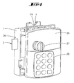
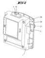
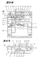
- cabinet lock can be attached to a cabinet door 25. It has a housing 1, which can be fixed inside the cabinet door 25 on the inside of the cabinet.
- the closure has a front panel 26 which can be fastened on the outside of the door.
- the front panel 26 has a handle 27 with which a crank pin 35 can be pivoted to displace a latch 3 arranged in the housing 1 in a latch displacement direction.
- the front panel 26 also has a keypad 28 for inputting a numerical code.
- a transponder reading device may be arranged to read a transponder.
- the shutter may also be connected to a fingerprint reader.
- the housing 1 is made of plastic.
- the bolt 3 is preferably made of metal.
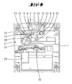
- the two locking stages 31, 34 is formed.
- In the locking slot 30 engages a locking extension 32 of a locking lever 33 a.
- the locking lever 33 can be pivoted by means of an electromagnet 29. It can assume a blocking position, in which the locking extension 32 is located in front of the locking stage 31 vor stressedem latch, so that the vorrosee latch of the handle 27 is not Wegschteurbar.
- the bolt can also be acted upon in the bolt retraction direction by a compression or tension spring, so that a single displacement of the locking lever 33 from the blocking position into a release position is required to retract the latch 3 from a latch position.
- the crank pin 35 which engages in a recess of the bolt 3, must be rotated.
- the locking slot 30 forms an additional blocking stage 34. Before this blocking stage 34, the locking extension 32 can lie in the locked-back locking position in order to lock the bolt 3 against preclusion.
- the insertion shaft 4 is formed by two shaft walls 22, 23, wherein a rear shaft wall 22 extends over the entire wide surface of the insertion shaft 4.
- the front-side shaft wall 23 extends only over a partial region of the broad side of the insertion shaft 4 and forms a Münzeinsteckbegrenzungssteg 24.
- the coin 5 is in fully inserted position. In this position, a portion of the coin 5 is located within the bulge 19. The apex of protruding from the housing 1 coin is outside the imaginary Einsteckschachtrandkante.
- a holding jaw 8 is attached on the shaft wall 22 .
- the holding jaw 8 is fastened with screws on the shaft wall 22 such that it can be adjusted in position.
- the fixed holding jaw 8 is transverse to Münzeinsteckides a movable holding jaw 7 opposite. Both holding jaws 7, 8 are able to partially enclose the coin 5 in such a way that it is positively secured against being pulled out of the insertion shaft 4.
- the coin 5 is therefore tied in a peripheral area> 180 °.
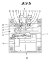
- the movable holding jaw 7 is associated with a rocker 6.
- the rocker 6 is designed T-shaped.
- the two T-legs form a bearing leg 10 and a guide groove 12.
- the T-bar forms the said movable holding jaw 7.
- the bearing leg 10 extends substantially parallel to the displacement direction of the bolt 3.
- a Swivel axis 9 attached to the housing or on the shaft wall 22.
- a substantially rectangular rib structure In the node of the rocker 6 is a substantially rectangular rib structure.
- the ribs 13, 14, 15, 16 and 17 frame up to a tour recess 11 a substantially rectangular space in which a touring pin 18 of the bolt 3 engages.
- the two ribs 13, 14 flanking the route recess 11 form blocking edges.
- the rib structure is continued in the direction of displacement of the bolt 3 behind the Tourenaus originallyung 11 and forms a guide groove 12 for the touring pin 18th
- the touring pin 18 is formed by a rectangular portion of the bolt 3 projecting beyond the back of the bolt 3. At the appropriate point protrudes over the front of the bolt 3 a round pin.
- the touring pin 18 is located on the opposite side of the locking slot 30 and is associated with an extension of the bolt 3.
- a blocking member 20 is arranged in the housing 1. This can be relocated with a needle-shaped tool 37, which is inserted into a housing opening 36. With a screw, not shown, it can be fixed in place.
- the blocking element 20 has a blocking pin 21 which can be inserted into the guide groove 12, so as to fix the rocker 6 in a position in which the TourenausEnglishung 11 lies in the path of movement of the touring pin 18. In this position, the bolt 3 can be moved even when not inserted coin 5. If the blocking element 20 is not blocked in its blocking position by means of a screw or the like, then the towing pin 18 can push the blocking pin 21 out of the guide groove 12 again when the catch 3 is completely closed.
- the rocker 6 is spring-loaded by a tension or compression spring, not shown, that when not inserted coin 5 of the touring pin 18 is located in front of the upper locking edge 13. This corresponds to a pivotal position of the rocker 6, in which the movable holding jaw 7 assumes a position closest to the fixed holding jaw 8. In this position, the bolt 3 can not be preconnected because the touring pin 18 can not enter the TourenausEnglishung 11, but runs against the locking edge 14 when the bolt 3 is to be moved.
- a coin 5 To be able to close the closure, a coin 5 must first be inserted into the insertion slot 4. The coin 5 is completely inserted into the insertion shaft 4 until it rests against the shaft bottom 24. In this state, there is still a sufficiently large portion of the coin 5 outside of the insertion shaft 4 or in the bulge 19, so that the Coin 5 by attack with two fingers from the insertion slot 4 can be pulled out again.
- the two holding jaws 7, 8 are initially spread apart by displacement of the movable holding jaw 7, then slightly approaching again until the coin 5 is held by a form-fitting Operaumgriff. If the coin 5 has the correct diameter, then the tour recess 11 lies in the movement path of the touring pin 18. When the blocking lever 33 is released, the bolt 3 can be locked in by actuating the handle 27. The touring pin 18 dives through the tour recess 11 and enters the flanked by two ribs guide groove 12 a. Once the touring pin 18 is immersed in the guide groove 12, the rocker 6 can not be pivoted. The coin 5 is thus tied in the insertion shaft 4 between the two holding jaws 7, 8.
- the latch 3 can be prefaced to its end position, in which the locking extension 32 occurs behind the locking step 31, so as to hold the latch 3 in the initial position.
- the bolt retraction is preferably carried out via a tension spring, not shown, as shown in the DE 198 32 516 A1 is described.
- the towing pin 18 is in front of the blocking flank 13 when the coin 5 is inserted.
- the bolt feed is blocked. If a coin 5 with a diameter that is too large is inserted into the insertion shaft 4, then the touring pin 18 is in front of the lower blocking edge 14 when the coin is fully inserted.
- the bolt 3 can not be displaced even in this position.
- the holding jaw 7 has a fferenein loft opening. If a screw is screwed into this screw-in opening, the pivotability of the rocker 6 is blocked.
- the fferenein loft opening of the holding jaw 7 is preferably aligned with a threaded opening of the shaft wall 23.
- the threaded opening is positioned such that in the screwed state, the rocker in Fig. 5 illustrated position occupies, in which the touring pin 18 is located in front of the tour recess 11, so that the bolt 3 can be preconnected.
- the lock can be used with such a permanently fixed rocker 6 as a cabinet lock without pledge function.
- the scanning device 7, 8 has a button or a microswitch.
- the button can be actuated by the rocker.
- the button is arranged so that it closes a circuit when the rocker their in Fig. 5 shown pivot position assumes that corresponds to the pivotal position with inserted matching coin 5.
- the circuit is not closed.
- the displacement lock of the bolt 3 is then preferably exerted electromagnetically, for example by the electromagnet 29. This can only relocate the barrier extension 32 in the release position when the circuit of the electrical scanning device is closed. Alternatively, it is also possible that an otherwise closed circuit is opened when properly inserted coin.
- a switching flag of a button or a switch directly scans the coin, so as to provide an electrical scanning signal.
Landscapes
- Engineering & Computer Science (AREA)
- Manufacturing & Machinery (AREA)
- Physics & Mathematics (AREA)
- General Physics & Mathematics (AREA)
- Coin-Freed Apparatuses For Hiring Articles (AREA)
- Control Of Vending Devices And Auxiliary Devices For Vending Devices (AREA)
Claims (16)
- Serrure d'armoire, avec un boîtier (1) et un pêne (3) y étant disposé, déplaçable par actionnement d'une manette (2), avec un puits d'enfichage (4), pour enficher une pièce de monnaie (5), avec un dispositif de palpage (7, 8), pour palper le diamètre de la pièce de monnaie (5) enfichée dans le puits d'enfichage (4) jusqu'à une position de palpage, le dispositif de palpage (7, 8) coopérant avec un dispositif de blocage (13, 14, 18), de manière que le pêne (3) n'est déplaçable que dans le cas où une pièce de monnaie (5) présente un diamètre approprié, caractérisée en ce que le dispositif de palpage (7, 8) forme une mâchoire de maintien (7), détenant, contre tout extraction, la pièce de monnaie (5), s'enfichant, à la position de palpage, de manière accessible par endroits depuis l'extérieur dans le puits d'enfichage (4), lorsque le pêne (3) est préalablement fermé.
- Fermeture d'armoire selon la revendication 1, caractérisée en ce que la mâchoire de maintien (7) est réalisée par un organe oscillant (6), monté à pivotement autour d'un axe (9) fixé au boîtier.
- Fermeture d'armoire selon l'une ou plusieurs des revendications précédentes, caractérisée en ce que l'organe oscillant (6) forme une branche de palier (10), à l'extrémité de laquelle l'axe (9) est disposé et dont la mâchoire de maintien (7) fait saillie sensiblement perpendiculairement.
- Fermeture d'armoire selon l'une ou plusieurs des revendications précédentes, caractérisée en ce que l'organe oscillant (6) forme un évidement pour rotation (11), flanqué par au moins un flanc de blocage (13, 14), pour l'entrée d'une tige de rotation (18) associée au pêne (3).
- Fermeture d'armoire selon l'une ou plusieurs des revendications précédentes, caractérisée en ce que la branche de palier (10) et une rainure de guidage (12), se raccordant à l'évidement pour rotation (11), s'étendent sensiblement parallèlement à la direction de déplacement du pêne.
- Fermeture d'armoire selon l'une ou plusieurs des revendications précédentes, caractérisée par une mâchoire de maintien (8) stationnaire, opposée à la mâchoire de maintien (7) pivotante.
- Fermeture d'armoire selon l'une ou plusieurs des revendications précédentes, caractérisée en ce que la distance d'espacement entre les deux mâchoires de maintien (7, 8) est réglable par un déplacement de la position de la mâchoire de maintien (8) stationnaire.
- Fermeture d'armoire selon l'une ou plusieurs des revendications précédentes, caractérisée en ce que le puits d'enfichage (4) présente une grosseur (19), dans laquelle est située une zone partielle de la pièce de monnaie (5) enfichée.
- Fermeture d'armoire selon l'une ou plusieurs des revendications précédentes, caractérisée par un organe de blocage (31, 32), maintenant, indépendamment du dispositif de blocage (13, 14, 18), le pêne (3) contre un déplacement du pêne dans la position de pêne refermée, et susceptible d'être libérée par un organe de libération (29).
- Fermeture d'armoire selon l'une ou plusieurs des revendications précédentes, caractérisée en ce que l'organe de libération (29) ne libère l'organe de blocage (31, 32) qu'après introduction d'un secret de clé.
- Fermeture d'armoire selon l'une ou plusieurs des revendications précédentes, caractérisée en ce que le secret de clé est susceptible d'être déterminé par un dispositif d'interrogation à transpondeur, par un dispositif de lecture d'empreinte digitale, une serrure cylindrique à pompe ou par l'intermédiaire d'un clavier.
- Fermeture d'armoire selon l'une ou plusieurs des revendications précédentes, caractérisée par une fonction d'amende financière, pour laquelle la fermeture d'armoire peut être ouverte à l'aide d'un secret de clé hiérarchiquement supérieur, en particulier un code de fermeture, la pièce de monnaie (5) peut être prélevée et la fermeture d'armoire peut être de nouveau fermée en contournant la fonction de palpage.
- Fermeture d'armoire selon l'une ou plusieurs des revendications précédentes, caractérisée par un outil auxiliaire, avec lequel le dispositif de palpage (7, 8) est susceptible d'être apporté en une position correspondant à la pièce de monnaie (5) enfichée dans le puits d'enfichage (4), et avec un élément de blocage (20), bloquant le dispositif de palpage (7, 8) en une position susceptible de déplacer le pêne (3).
- Fermeture d'armoire selon l'une ou plusieurs des revendications précédentes, caractérisée par un téton de blocage (21), constitué par l'élément de blocage (20), pouvant s'engager dans une rainure de guidage (12) de l'organe oscillant (6), pour bloquer l'organe oscillant (6) en une position pivotée dans laquelle le pêne (3) peut être préalablement fermé.
- Fermeture d'armoire selon l'une ou plusieurs des revendications précédentes, caractérisée en ce que l'organe oscillant (6) peut être fixé avec une vis.
- Fermeture d'armoire selon l'une ou plusieurs des revendications précédentes, caractérisée par un interrupteur ou palpeur, associé au dispositif de palpage (7, 8), pour la fourniture d'un signal électrique, avec lequel le mouvement de déplacement du pêne (3) est susceptible d'être bloqué dans le cas où une pièce de monnaie n'est pas introduite ou dans le cas où une pièce de monnaie introduite n'est pas appropriée.
Applications Claiming Priority (1)
| Application Number | Priority Date | Filing Date | Title |
|---|---|---|---|
| DE200710052583 DE102007052583A1 (de) | 2007-10-29 | 2007-10-29 | Münzpfandschrankverschluss |
Publications (3)
| Publication Number | Publication Date |
|---|---|
| EP2055871A2 EP2055871A2 (fr) | 2009-05-06 |
| EP2055871A3 EP2055871A3 (fr) | 2010-08-04 |
| EP2055871B1 true EP2055871B1 (fr) | 2012-06-20 |
Family
ID=40130903
Family Applications (1)
| Application Number | Title | Priority Date | Filing Date |
|---|---|---|---|
| EP20080167517 Not-in-force EP2055871B1 (fr) | 2007-10-29 | 2008-10-24 | Fermeture d'armoire de consigne à pièces de monnaies |
Country Status (4)
| Country | Link |
|---|---|
| US (1) | US7748512B2 (fr) |
| EP (1) | EP2055871B1 (fr) |
| DE (1) | DE102007052583A1 (fr) |
| ES (1) | ES2389522T3 (fr) |
Cited By (1)
| Publication number | Priority date | Publication date | Assignee | Title |
|---|---|---|---|---|
| DE102017113463B3 (de) | 2017-06-20 | 2018-07-12 | W&F Locks Ohg | Hebelschloss |
Families Citing this family (2)
| Publication number | Priority date | Publication date | Assignee | Title |
|---|---|---|---|---|
| SE532298C2 (sv) * | 2008-04-16 | 2009-12-08 | Jokab Safety Ab | Låsanordning |
| DE102015113243B4 (de) | 2015-08-11 | 2023-10-12 | Schulte-Schlagbaum Aktiengesellschaft | Drahtlos mit einer Zentraleinheit kommunizierendes Schranktürschloss |
Family Cites Families (10)
| Publication number | Priority date | Publication date | Assignee | Title |
|---|---|---|---|---|
| US1633411A (en) * | 1925-12-29 | 1927-06-21 | Frederick W Kassler | Coin-controlled lock |
| US2034359A (en) * | 1934-06-07 | 1936-03-17 | Isaac J Segal | Lock |
| DE3242045A1 (de) * | 1982-11-13 | 1984-05-17 | Schulte-Schlagbaum Ag, 5620 Velbert | Schloss, insbesondere pfandschloss |
| US5573098A (en) * | 1995-03-01 | 1996-11-12 | Minnesota Lock, Inc. | Card-activated lock mechanism |
| DE19515765A1 (de) | 1995-04-28 | 1996-10-31 | Peter Fuchs | Münzpfandschloß |
| DE19527066C2 (de) | 1995-07-25 | 2002-11-14 | Mauer Gmbh | Schloßaufsatz |
| DE19832516A1 (de) | 1998-07-20 | 2000-01-27 | Schulte Schlagbaum Ag | Schloß, insbesondere für eine Schließanlage |
| DE10350951B4 (de) | 2003-10-30 | 2008-02-07 | Schulte-Schlagbaum Ag | Schloss mit nach Münzeinwurf zu betätigender Schließfunktion |
| EP1821267A1 (fr) * | 2006-02-09 | 2007-08-22 | Somers Co., Ltd. | Structure de verrouillage |
| DE102006034292A1 (de) | 2006-07-21 | 2008-01-24 | Schulte-Schlagbaum Ag | Tastaturcodeschloss |
-
2007
- 2007-10-29 DE DE200710052583 patent/DE102007052583A1/de not_active Withdrawn
-
2008
- 2008-10-24 EP EP20080167517 patent/EP2055871B1/fr not_active Not-in-force
- 2008-10-24 ES ES08167517T patent/ES2389522T3/es active Active
- 2008-11-03 US US12/263,833 patent/US7748512B2/en not_active Expired - Fee Related
Cited By (1)
| Publication number | Priority date | Publication date | Assignee | Title |
|---|---|---|---|---|
| DE102017113463B3 (de) | 2017-06-20 | 2018-07-12 | W&F Locks Ohg | Hebelschloss |
Also Published As
| Publication number | Publication date |
|---|---|
| EP2055871A2 (fr) | 2009-05-06 |
| ES2389522T3 (es) | 2012-10-26 |
| EP2055871A3 (fr) | 2010-08-04 |
| US7748512B2 (en) | 2010-07-06 |
| US20090113951A1 (en) | 2009-05-07 |
| DE102007052583A1 (de) | 2009-04-30 |
Similar Documents
| Publication | Publication Date | Title |
|---|---|---|
| DE19701761C1 (de) | Selbstverriegelndes Schloß | |
| EP2703586B1 (fr) | Dispositif de serrure pour vantail passif doté d'un dispositif de détection | |
| DE102008011551B4 (de) | Selbstverriegelnde Zusatzverriegelung | |
| DE60308825T2 (de) | Sicherheitslagerungsvorrichtung | |
| DE10194835B4 (de) | Hebelverschluss | |
| EP3299550A1 (fr) | Ouverture de porte électrique pour porte battante pourvue d'un verrou magnétique | |
| EP0410122B1 (fr) | Serrure insérée avec système de fixation de pêne demi-tour | |
| EP2055871B1 (fr) | Fermeture d'armoire de consigne à pièces de monnaies | |
| DE3926132C2 (fr) | ||
| DE102005015248B4 (de) | Standflügelschloss mit einem elektrischen Türöffner | |
| EP0799956A2 (fr) | Serrure | |
| DE3124180C2 (fr) | ||
| DE202021101478U1 (de) | Falle für ein Türschloss und Türschloss mit einer derartigen Falle | |
| DE10350951B4 (de) | Schloss mit nach Münzeinwurf zu betätigender Schließfunktion | |
| DE3801672C2 (fr) | ||
| DE202009007674U1 (de) | Treibstangenschloss mit Mehrfachverriegelung | |
| DE202007016091U1 (de) | Treibstangenschloss | |
| DE102006005996A1 (de) | Türschloss in Verbindung mit elektrischem Türöffner für mechanisch selbst stellende Mehrfach-Verriegelung | |
| DE280390C (fr) | ||
| DE10024683A1 (de) | Schloss mit Vorschlussvergrößerung und Panikfunktion | |
| DE102004037159B4 (de) | Kassenschublade | |
| DE102008016317B4 (de) | Schloss mit einer Anordnung zur Fallendrehung | |
| DE102012111537A1 (de) | Schloss mit einer freigebbaren Dreheinheit | |
| EP0136570A2 (fr) | Dispositif pour arrêter des éléments mobiles l'un par rapport à l'autre | |
| DE9207865U1 (de) | Durch einen Schlüssel- und/oder durch einen Drücker betätigbares Antipanik-Hotelschloß |
Legal Events
| Date | Code | Title | Description |
|---|---|---|---|
| PUAI | Public reference made under article 153(3) epc to a published international application that has entered the european phase |
Free format text: ORIGINAL CODE: 0009012 |
|
| AK | Designated contracting states |
Kind code of ref document: A2 Designated state(s): AT BE BG CH CY CZ DE DK EE ES FI FR GB GR HR HU IE IS IT LI LT LU LV MC MT NL NO PL PT RO SE SI SK TR |
|
| AX | Request for extension of the european patent |
Extension state: AL BA MK RS |
|
| PUAL | Search report despatched |
Free format text: ORIGINAL CODE: 0009013 |
|
| AK | Designated contracting states |
Kind code of ref document: A3 Designated state(s): AT BE BG CH CY CZ DE DK EE ES FI FR GB GR HR HU IE IS IT LI LT LU LV MC MT NL NO PL PT RO SE SI SK TR |
|
| AX | Request for extension of the european patent |
Extension state: AL BA MK RS |
|
| RIC1 | Information provided on ipc code assigned before grant |
Ipc: E05B 47/00 20060101AFI20081230BHEP Ipc: G07C 9/00 20060101ALI20100630BHEP Ipc: E05B 47/06 20060101ALI20100630BHEP |
|
| 17P | Request for examination filed |
Effective date: 20110128 |
|
| AKX | Designation fees paid |
Designated state(s): AT BE BG CH CY CZ DE DK EE ES FI FR GB GR HR HU IE IS IT LI LT LU LV MC MT NL NO PL PT RO SE SI SK TR |
|
| RIC1 | Information provided on ipc code assigned before grant |
Ipc: E05B 47/00 20060101AFI20111228BHEP Ipc: E05B 47/06 20060101ALI20111228BHEP Ipc: G07C 9/00 20060101ALI20111228BHEP |
|
| GRAP | Despatch of communication of intention to grant a patent |
Free format text: ORIGINAL CODE: EPIDOSNIGR1 |
|
| GRAS | Grant fee paid |
Free format text: ORIGINAL CODE: EPIDOSNIGR3 |
|
| GRAA | (expected) grant |
Free format text: ORIGINAL CODE: 0009210 |
|
| AK | Designated contracting states |
Kind code of ref document: B1 Designated state(s): AT BE BG CH CY CZ DE DK EE ES FI FR GB GR HR HU IE IS IT LI LT LU LV MC MT NL NO PL PT RO SE SI SK TR |
|
| REG | Reference to a national code |
Ref country code: GB Ref legal event code: FG4D Free format text: NOT ENGLISH |
|
| REG | Reference to a national code |
Ref country code: CH Ref legal event code: EP |
|
| REG | Reference to a national code |
Ref country code: AT Ref legal event code: REF Ref document number: 563188 Country of ref document: AT Kind code of ref document: T Effective date: 20120715 |
|
| REG | Reference to a national code |
Ref country code: IE Ref legal event code: FG4D Free format text: LANGUAGE OF EP DOCUMENT: GERMAN |
|
| REG | Reference to a national code |
Ref country code: CH Ref legal event code: NV Representative=s name: R. A. EGLI & CO. PATENTANWAELTE |
|
| REG | Reference to a national code |
Ref country code: DE Ref legal event code: R096 Ref document number: 502008007468 Country of ref document: DE Effective date: 20120816 |
|
| REG | Reference to a national code |
Ref country code: NL Ref legal event code: T3 |
|
| REG | Reference to a national code |
Ref country code: SE Ref legal event code: TRGR |
|
| REG | Reference to a national code |
Ref country code: ES Ref legal event code: FG2A Ref document number: 2389522 Country of ref document: ES Kind code of ref document: T3 Effective date: 20121026 |
|
| PG25 | Lapsed in a contracting state [announced via postgrant information from national office to epo] |
Ref country code: LT Free format text: LAPSE BECAUSE OF FAILURE TO SUBMIT A TRANSLATION OF THE DESCRIPTION OR TO PAY THE FEE WITHIN THE PRESCRIBED TIME-LIMIT Effective date: 20120620 Ref country code: FI Free format text: LAPSE BECAUSE OF FAILURE TO SUBMIT A TRANSLATION OF THE DESCRIPTION OR TO PAY THE FEE WITHIN THE PRESCRIBED TIME-LIMIT Effective date: 20120620 Ref country code: NO Free format text: LAPSE BECAUSE OF FAILURE TO SUBMIT A TRANSLATION OF THE DESCRIPTION OR TO PAY THE FEE WITHIN THE PRESCRIBED TIME-LIMIT Effective date: 20120920 |
|
| REG | Reference to a national code |
Ref country code: LT Ref legal event code: MG4D Effective date: 20120620 |
|
| PG25 | Lapsed in a contracting state [announced via postgrant information from national office to epo] |
Ref country code: SI Free format text: LAPSE BECAUSE OF FAILURE TO SUBMIT A TRANSLATION OF THE DESCRIPTION OR TO PAY THE FEE WITHIN THE PRESCRIBED TIME-LIMIT Effective date: 20120620 Ref country code: GR Free format text: LAPSE BECAUSE OF FAILURE TO SUBMIT A TRANSLATION OF THE DESCRIPTION OR TO PAY THE FEE WITHIN THE PRESCRIBED TIME-LIMIT Effective date: 20120921 Ref country code: HR Free format text: LAPSE BECAUSE OF FAILURE TO SUBMIT A TRANSLATION OF THE DESCRIPTION OR TO PAY THE FEE WITHIN THE PRESCRIBED TIME-LIMIT Effective date: 20120620 Ref country code: LV Free format text: LAPSE BECAUSE OF FAILURE TO SUBMIT A TRANSLATION OF THE DESCRIPTION OR TO PAY THE FEE WITHIN THE PRESCRIBED TIME-LIMIT Effective date: 20120620 |
|
| PG25 | Lapsed in a contracting state [announced via postgrant information from national office to epo] |
Ref country code: SK Free format text: LAPSE BECAUSE OF FAILURE TO SUBMIT A TRANSLATION OF THE DESCRIPTION OR TO PAY THE FEE WITHIN THE PRESCRIBED TIME-LIMIT Effective date: 20120620 Ref country code: EE Free format text: LAPSE BECAUSE OF FAILURE TO SUBMIT A TRANSLATION OF THE DESCRIPTION OR TO PAY THE FEE WITHIN THE PRESCRIBED TIME-LIMIT Effective date: 20120620 Ref country code: CY Free format text: LAPSE BECAUSE OF FAILURE TO SUBMIT A TRANSLATION OF THE DESCRIPTION OR TO PAY THE FEE WITHIN THE PRESCRIBED TIME-LIMIT Effective date: 20120620 Ref country code: CZ Free format text: LAPSE BECAUSE OF FAILURE TO SUBMIT A TRANSLATION OF THE DESCRIPTION OR TO PAY THE FEE WITHIN THE PRESCRIBED TIME-LIMIT Effective date: 20120620 Ref country code: IS Free format text: LAPSE BECAUSE OF FAILURE TO SUBMIT A TRANSLATION OF THE DESCRIPTION OR TO PAY THE FEE WITHIN THE PRESCRIBED TIME-LIMIT Effective date: 20121020 Ref country code: RO Free format text: LAPSE BECAUSE OF FAILURE TO SUBMIT A TRANSLATION OF THE DESCRIPTION OR TO PAY THE FEE WITHIN THE PRESCRIBED TIME-LIMIT Effective date: 20120620 |
|
| PG25 | Lapsed in a contracting state [announced via postgrant information from national office to epo] |
Ref country code: IT Free format text: LAPSE BECAUSE OF FAILURE TO SUBMIT A TRANSLATION OF THE DESCRIPTION OR TO PAY THE FEE WITHIN THE PRESCRIBED TIME-LIMIT Effective date: 20120620 Ref country code: PT Free format text: LAPSE BECAUSE OF FAILURE TO SUBMIT A TRANSLATION OF THE DESCRIPTION OR TO PAY THE FEE WITHIN THE PRESCRIBED TIME-LIMIT Effective date: 20121022 Ref country code: PL Free format text: LAPSE BECAUSE OF FAILURE TO SUBMIT A TRANSLATION OF THE DESCRIPTION OR TO PAY THE FEE WITHIN THE PRESCRIBED TIME-LIMIT Effective date: 20120620 |
|
| PLBE | No opposition filed within time limit |
Free format text: ORIGINAL CODE: 0009261 |
|
| STAA | Information on the status of an ep patent application or granted ep patent |
Free format text: STATUS: NO OPPOSITION FILED WITHIN TIME LIMIT |
|
| PG25 | Lapsed in a contracting state [announced via postgrant information from national office to epo] |
Ref country code: DK Free format text: LAPSE BECAUSE OF FAILURE TO SUBMIT A TRANSLATION OF THE DESCRIPTION OR TO PAY THE FEE WITHIN THE PRESCRIBED TIME-LIMIT Effective date: 20120620 |
|
| 26N | No opposition filed |
Effective date: 20130321 |
|
| PG25 | Lapsed in a contracting state [announced via postgrant information from national office to epo] |
Ref country code: MC Free format text: LAPSE BECAUSE OF NON-PAYMENT OF DUE FEES Effective date: 20121031 |
|
| REG | Reference to a national code |
Ref country code: DE Ref legal event code: R097 Ref document number: 502008007468 Country of ref document: DE Effective date: 20130321 |
|
| REG | Reference to a national code |
Ref country code: IE Ref legal event code: MM4A |
|
| PG25 | Lapsed in a contracting state [announced via postgrant information from national office to epo] |
Ref country code: BG Free format text: LAPSE BECAUSE OF FAILURE TO SUBMIT A TRANSLATION OF THE DESCRIPTION OR TO PAY THE FEE WITHIN THE PRESCRIBED TIME-LIMIT Effective date: 20120920 Ref country code: IE Free format text: LAPSE BECAUSE OF NON-PAYMENT OF DUE FEES Effective date: 20121024 |
|
| PG25 | Lapsed in a contracting state [announced via postgrant information from national office to epo] |
Ref country code: MT Free format text: LAPSE BECAUSE OF FAILURE TO SUBMIT A TRANSLATION OF THE DESCRIPTION OR TO PAY THE FEE WITHIN THE PRESCRIBED TIME-LIMIT Effective date: 20120620 |
|
| PG25 | Lapsed in a contracting state [announced via postgrant information from national office to epo] |
Ref country code: TR Free format text: LAPSE BECAUSE OF FAILURE TO SUBMIT A TRANSLATION OF THE DESCRIPTION OR TO PAY THE FEE WITHIN THE PRESCRIBED TIME-LIMIT Effective date: 20120620 |
|
| PG25 | Lapsed in a contracting state [announced via postgrant information from national office to epo] |
Ref country code: LU Free format text: LAPSE BECAUSE OF NON-PAYMENT OF DUE FEES Effective date: 20121024 |
|
| PG25 | Lapsed in a contracting state [announced via postgrant information from national office to epo] |
Ref country code: HU Free format text: LAPSE BECAUSE OF FAILURE TO SUBMIT A TRANSLATION OF THE DESCRIPTION OR TO PAY THE FEE WITHIN THE PRESCRIBED TIME-LIMIT Effective date: 20081024 |
|
| PGFP | Annual fee paid to national office [announced via postgrant information from national office to epo] |
Ref country code: ES Payment date: 20141009 Year of fee payment: 7 Ref country code: GB Payment date: 20141013 Year of fee payment: 7 Ref country code: CH Payment date: 20141013 Year of fee payment: 7 Ref country code: SE Payment date: 20141013 Year of fee payment: 7 Ref country code: FR Payment date: 20141008 Year of fee payment: 7 |
|
| PGFP | Annual fee paid to national office [announced via postgrant information from national office to epo] |
Ref country code: NL Payment date: 20141009 Year of fee payment: 7 Ref country code: AT Payment date: 20141009 Year of fee payment: 7 |
|
| PGFP | Annual fee paid to national office [announced via postgrant information from national office to epo] |
Ref country code: BE Payment date: 20141020 Year of fee payment: 7 |
|
| REG | Reference to a national code |
Ref country code: SE Ref legal event code: EUG Ref country code: CH Ref legal event code: PL |
|
| REG | Reference to a national code |
Ref country code: AT Ref legal event code: MM01 Ref document number: 563188 Country of ref document: AT Kind code of ref document: T Effective date: 20151024 |
|
| GBPC | Gb: european patent ceased through non-payment of renewal fee |
Effective date: 20151024 |
|
| REG | Reference to a national code |
Ref country code: NL Ref legal event code: MM Effective date: 20151101 |
|
| PG25 | Lapsed in a contracting state [announced via postgrant information from national office to epo] |
Ref country code: LI Free format text: LAPSE BECAUSE OF NON-PAYMENT OF DUE FEES Effective date: 20151031 Ref country code: CH Free format text: LAPSE BECAUSE OF NON-PAYMENT OF DUE FEES Effective date: 20151031 Ref country code: GB Free format text: LAPSE BECAUSE OF NON-PAYMENT OF DUE FEES Effective date: 20151024 |
|
| REG | Reference to a national code |
Ref country code: FR Ref legal event code: ST Effective date: 20160630 |
|
| PG25 | Lapsed in a contracting state [announced via postgrant information from national office to epo] |
Ref country code: NL Free format text: LAPSE BECAUSE OF NON-PAYMENT OF DUE FEES Effective date: 20151101 Ref country code: AT Free format text: LAPSE BECAUSE OF NON-PAYMENT OF DUE FEES Effective date: 20151024 Ref country code: SE Free format text: LAPSE BECAUSE OF NON-PAYMENT OF DUE FEES Effective date: 20151025 Ref country code: FR Free format text: LAPSE BECAUSE OF NON-PAYMENT OF DUE FEES Effective date: 20151102 |
|
| PG25 | Lapsed in a contracting state [announced via postgrant information from national office to epo] |
Ref country code: ES Free format text: LAPSE BECAUSE OF NON-PAYMENT OF DUE FEES Effective date: 20151025 |
|
| PG25 | Lapsed in a contracting state [announced via postgrant information from national office to epo] |
Ref country code: BE Free format text: LAPSE BECAUSE OF NON-PAYMENT OF DUE FEES Effective date: 20151031 |
|
| PGFP | Annual fee paid to national office [announced via postgrant information from national office to epo] |
Ref country code: DE Payment date: 20171016 Year of fee payment: 10 |
|
| REG | Reference to a national code |
Ref country code: DE Ref legal event code: R119 Ref document number: 502008007468 Country of ref document: DE |
|
| PG25 | Lapsed in a contracting state [announced via postgrant information from national office to epo] |
Ref country code: DE Free format text: LAPSE BECAUSE OF NON-PAYMENT OF DUE FEES Effective date: 20190501 |