EP2055877A1 - Klebeverfahren eines Montageteils auf eine Oberfläche - Google Patents
Klebeverfahren eines Montageteils auf eine Oberfläche Download PDFInfo
- Publication number
- EP2055877A1 EP2055877A1 EP08168311A EP08168311A EP2055877A1 EP 2055877 A1 EP2055877 A1 EP 2055877A1 EP 08168311 A EP08168311 A EP 08168311A EP 08168311 A EP08168311 A EP 08168311A EP 2055877 A1 EP2055877 A1 EP 2055877A1
- Authority
- EP
- European Patent Office
- Prior art keywords
- groove
- mounting piece
- glue
- bonding surface
- adhesive
- Prior art date
- Legal status (The legal status is an assumption and is not a legal conclusion. Google has not performed a legal analysis and makes no representation as to the accuracy of the status listed.)
- Withdrawn
Links
- 238000000034 method Methods 0.000 title claims abstract description 17
- 238000004026 adhesive bonding Methods 0.000 title claims abstract description 12
- 239000003292 glue Substances 0.000 claims abstract description 45
- 238000000151 deposition Methods 0.000 claims abstract description 3
- 239000000853 adhesive Substances 0.000 claims description 18
- 230000001070 adhesive effect Effects 0.000 claims description 18
- 230000000750 progressive effect Effects 0.000 claims description 6
- 230000000717 retained effect Effects 0.000 abstract description 2
- 239000000463 material Substances 0.000 description 6
- 239000011521 glass Substances 0.000 description 5
- KFZMGEQAYNKOFK-UHFFFAOYSA-N Isopropanol Chemical compound CC(C)O KFZMGEQAYNKOFK-UHFFFAOYSA-N 0.000 description 3
- 238000006116 polymerization reaction Methods 0.000 description 3
- 239000002313 adhesive film Substances 0.000 description 2
- 238000009826 distribution Methods 0.000 description 2
- 230000000694 effects Effects 0.000 description 2
- 230000014759 maintenance of location Effects 0.000 description 2
- BASFCYQUMIYNBI-UHFFFAOYSA-N platinum Chemical compound [Pt] BASFCYQUMIYNBI-UHFFFAOYSA-N 0.000 description 2
- 230000002411 adverse Effects 0.000 description 1
- 238000005452 bending Methods 0.000 description 1
- 239000000428 dust Substances 0.000 description 1
- 238000001764 infiltration Methods 0.000 description 1
- 230000008595 infiltration Effects 0.000 description 1
- 238000004519 manufacturing process Methods 0.000 description 1
- 230000002093 peripheral effect Effects 0.000 description 1
- 229910052697 platinum Inorganic materials 0.000 description 1
- 238000003825 pressing Methods 0.000 description 1
- 238000007790 scraping Methods 0.000 description 1
- 238000006748 scratching Methods 0.000 description 1
- 230000002393 scratching effect Effects 0.000 description 1
- 238000003892 spreading Methods 0.000 description 1
- 239000010409 thin film Substances 0.000 description 1
Images

Classifications
-
- E—FIXED CONSTRUCTIONS
- E05—LOCKS; KEYS; WINDOW OR DOOR FITTINGS; SAFES
- E05D—HINGES OR SUSPENSION DEVICES FOR DOORS, WINDOWS OR WINGS
- E05D5/00—Construction of single parts, e.g. the parts for attachment
- E05D5/02—Parts for attachment, e.g. flaps
- E05D5/0246—Parts for attachment, e.g. flaps for attachment to glass panels
-
- C—CHEMISTRY; METALLURGY
- C09—DYES; PAINTS; POLISHES; NATURAL RESINS; ADHESIVES; COMPOSITIONS NOT OTHERWISE PROVIDED FOR; APPLICATIONS OF MATERIALS NOT OTHERWISE PROVIDED FOR
- C09J—ADHESIVES; NON-MECHANICAL ASPECTS OF ADHESIVE PROCESSES IN GENERAL; ADHESIVE PROCESSES NOT PROVIDED FOR ELSEWHERE; USE OF MATERIALS AS ADHESIVES
- C09J5/00—Adhesive processes in general; Adhesive processes not provided for elsewhere, e.g. relating to primers
- C09J5/04—Adhesive processes in general; Adhesive processes not provided for elsewhere, e.g. relating to primers involving separate application of adhesive ingredients to the different surfaces to be joined
-
- F—MECHANICAL ENGINEERING; LIGHTING; HEATING; WEAPONS; BLASTING
- F16—ENGINEERING ELEMENTS AND UNITS; GENERAL MEASURES FOR PRODUCING AND MAINTAINING EFFECTIVE FUNCTIONING OF MACHINES OR INSTALLATIONS; THERMAL INSULATION IN GENERAL
- F16B—DEVICES FOR FASTENING OR SECURING CONSTRUCTIONAL ELEMENTS OR MACHINE PARTS TOGETHER, e.g. NAILS, BOLTS, CIRCLIPS, CLAMPS, CLIPS OR WEDGES; JOINTS OR JOINTING
- F16B11/00—Connecting constructional elements or machine parts by sticking or pressing them together, e.g. cold pressure welding
- F16B11/006—Connecting constructional elements or machine parts by sticking or pressing them together, e.g. cold pressure welding by gluing
-
- E—FIXED CONSTRUCTIONS
- E05—LOCKS; KEYS; WINDOW OR DOOR FITTINGS; SAFES
- E05D—HINGES OR SUSPENSION DEVICES FOR DOORS, WINDOWS OR WINGS
- E05D9/00—Flaps or sleeves specially designed for making from particular material, e.g. hoop-iron, sheet metal, plastics
-
- E—FIXED CONSTRUCTIONS
- E05—LOCKS; KEYS; WINDOW OR DOOR FITTINGS; SAFES
- E05Y—INDEXING SCHEME ASSOCIATED WITH SUBCLASSES E05D AND E05F, RELATING TO CONSTRUCTION ELEMENTS, ELECTRIC CONTROL, POWER SUPPLY, POWER SIGNAL OR TRANSMISSION, USER INTERFACES, MOUNTING OR COUPLING, DETAILS, ACCESSORIES, AUXILIARY OPERATIONS NOT OTHERWISE PROVIDED FOR, APPLICATION THEREOF
- E05Y2600/00—Mounting or coupling arrangements for elements provided for in this subclass
- E05Y2600/50—Mounting methods; Positioning
- E05Y2600/52—Toolless
- E05Y2600/526—Gluing or cementing
Definitions
- the invention relates to a method of bonding a mounting piece to a plane support, and to a mounting piece to be glued to a plane support.
- the invention makes it possible to simplify and speed up the process of bonding a mounting piece to a surface, as well as to improve the final aesthetic appearance of said gluing.
- the mounting piece may be one of the plates of a hinge, to be fixed on a glass panel.
- Bonding a piece to a surface of translucent material has aesthetic constraints.
- it is preferable that the adhesive film ensuring the adherence of the part is not visible.
- an excessive amount of glue is often deposited on the workpiece to be glued and then allowed to overflow on the sides.
- some manufacturers have proposed precolling masks, in the form of thin films stickers. Once these masks are positioned, the glue is injected into the space reserved for gluing and the piece is pressed against the translucent surface. After polymerization of the glue, the mask is removed, eliminating the excess glue. This system requires the manufacture of additional parts and a large number of minute operations.
- the present invention proposes to simplify and accelerate the process of bonding a mounting piece to a surface by limiting the number of parts and operations required, while preserving the quality of the parts to be bonded and improving the quality of the parts to be bonded. final aesthetic aspect of the collage.
- the invention relates to a method of bonding a mounting piece to a flat support, consisting of depositing a quantity of adhesive on a bonding surface of the mounting piece bordered by a groove formed in said mounting piece. applying pressure on the parts to be bonded and, finally, allowing the adhesive to cure, characterized in that the adhesive is deposited only on a bonding surface of the mounting part bordered by a groove formed in said mounting piece and to retain the excess adhesive deposited on the bonding surface when pressure is exerted on the parts to be bonded and in that pushes the glue to an area where the bonding surface is flared in the groove by a progressive connection.
- the groove is closed on itself.
- the glue deposit made in the median portion of the bonding surface has an approximately homothetic shape of the outline of the groove.
- the adhesive is deposited in the form of a point centered on said surface so that when a uniform pressure is exerted on the parts to be bonded, the adhesive spreads covering the entire circular surface.
- the bonding surface may also have an elliptical shape.
- the ratio defined between the length of the major axis of the ellipse and that of its minor axis is less than 2.
- the glue is deposited on said surface in the form of a line centered on and merged with the major axis of the ellipse, of determined length, less than the length of the major axis, so that when a uniform pressure is exerted on the parts to be glued, the glue spreads out covering the entire elliptical surface.
- the glue even in excess, does not extend beyond the groove.
- the resulting collage therefore has a clean appearance of a chosen geometry which is that of the groove and not the random result of the spreading of the glue.
- the invention relates to a mounting piece, comprising a face intended to be glued on a plane support, said face having at least one bonding surface bordered by a groove for retaining an excess of adhesive deposited on the surface of bonding when said piece is applied to said support to which it is to be attached, and wherein the connection between the bonding surface and the groove is a progressive connection.
- This mounting piece can be for example one of the plates of a door hinge.
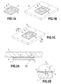
- FIGS 1a to 1c represent the different steps of the bonding process according to the present invention.
- the mounting piece 1 for implementing the method according to the invention has a bonding surface 4 circumscribed by a closed groove 5, and intended to adhere to a plate of translucent material 2.
- a bonding surface 4 circumscribed by a closed groove 5, and intended to adhere to a plate of translucent material 2.
- To obtain a clean and resistant bond it is known to well degrease the bonding surface, and leave no trace of residual moisture. It is possible to use for this purpose isopropyl alcohol for example. It is then necessary to distribute the adhesive correctly on the bonding surface 4, as shown in FIG. figure 1a . This distribution is difficult to dose and center, so that it is almost impossible to obtain a glue surface of predetermined regular shape.
- the glue can, however, be distributed differently according to the shape of the bonding surface, so as to obtain a covering of all of said surface as uniform as possible.
- the glue in the case of a circular gluing surface, the glue will be deposited as a dot or a circle.
- the adhesive in the case of an elliptical bonding surface, as described in the figure 1a the adhesive will preferably be deposited in the form of a line centered on and coincident with the major axis of the ellipse, of length less than the length of the major axis thereof.
- the glue arrangement should be such a line of about 7 mm in length. In this way, under uniform pressure, the glue simultaneously reaches all the edges of the elliptical surface.
- a rectangular or square glue surface it has been found that homogeneous distribution is obtained by arranging the glue in the form of a very rounded Greek cross.
- FIG. 1 shows a rectangular mounting part 1 provided with a groove 5 in the form of an ellipse
- other forms of grooves may therefore be provided.
- it may even be provided to provide two or more closed grooves on one side of the mounting piece to be bonded.
- the glue should then be properly distributed between the different bonding surfaces.
- a bonding on an elliptical, and preferably round, surface is optimal from the point of view of tear resistance.
- a pressure is applied between the two pieces to be bonded 1, 2 so as to spread the glue 3 over the whole of the gluing surface 4.
- the glue is pushed towards an area where the flow section of the glue s' gradually fades into the groove.
- the excess glue is retained in the groove 5.
- the glue appears in the form of a transparent and regular outline barely visible on the glass and forming a decorative element ( Fig. 1 C ).
- FIG. 2a and 2b a sectional view along axis II-II of a mounting piece 1 according to the present invention is shown glued to a plate of translucent material 2 and having a closed groove 5 formed on one of its faces, delimiting the bonding surface 4.
- the bonding surface is completely covered and the groove fulfills its function of retention of the overflow of glue.
- the mounting piece that is desired to be glued has a square or rectangular surface, it should be written a circular or elliptical groove having the largest possible dimensions, while maintaining a small outer surface 6 surrounding the groove.
- the connection between this outer surface 6 and the groove 5 is not subject to any constraints apart from aesthetic needs. However, it is best to configure the mounting piece so that the bonding surface 4 and the surface 6 surrounding the groove are substantially in the same plane. As the adhesive thickness is generally negligible, the surface 6 surrounding the groove is almost pressed against the surface of translucent material, and the infiltration of dust between the surface of translucent material and the outer surface surrounding the groove is thus avoided.
- the figure 2b represents an enlarged view of the connection between the bonding surface 4 and the closed groove 5.
- the bonding surface 4 flares in said groove 5 by a progressive connection.
- Progressive connection is understood to mean a connection having no discontinuity.
- the flow section of the glue 3 thus gradually fades in the groove 5.
- the connection does not show any sudden break in the flow section that is offered to the glue, which improves the both the aesthetic aspect of the peripheral region of the bonding surface and the resistance of the bonding to pulling stresses.
- this angle is small.
- the connection angle ⁇ has a value less than 30 °. More preferably, the connection angle ⁇ is set at 20 °.
- Such a very progressive connection effectively limits the concentration factor of the stresses exerted on the glue joint formed in the groove under pulling stresses.
- the volume of the groove 5 depends on the area of the bonding surface 4 and takes into account the inaccuracy of the volume of adhesive deposited. To ensure largely the retention of any overflow of glue, the groove must represent a volume at least twice the volume of glue necessary for gluing the surface it surrounds.
- the figure 3 represents two examples of mounting parts according to the present invention, in this case, two plates 1a and 1b of a hinge 100 particularly adapted to be glued between two possibly translucent panels.
- Each plate has structural characteristics identical to those of the mounting piece according to the invention, defined in the previous figures.
- the numerical references used on the Figures 3 to 5 are therefore the same as in the previous figures, but are followed by the letters a or b according to the plate to which reference is made.
- the plate 1a has two knuckles at the hinge. Platinum 1b has three.
- the two plates 1a and 1b have a symmetry along a median axis XX perpendicular to the axis of rotation AA of the hinge.
- Such symmetry enhances the bond strength, avoiding the deformation usually occurs in case of heavy load applied to the hinge.
- This deformation has the adverse effect that the bonding works in peeling, that is to say that simultaneously appear a tensile stress on a small bonded surface and a bending stress on the plate.
- the peel-resistant surface is larger and the glue offers increased strength because the stress is better distributed over the height of the hinge. The peeling effect is thus reduced and the hinge remains flat.
- each plate 1a or 1b has on one of its faces a groove 5a (respectively 5b), and on the other a groove 5a '(respectively 5b'), so that said plate can be assembled indifferently in one direction or in the other.
- the non-bonded face of each plate thus has a groove 5a '(respectively 5b') filling an exclusively aesthetic function, as shown in FIG. figure 4 .
- the system is flexible, which is not the case of a conventional hinge consisting of two plates with two knuckles per hinge. The groove thus contributes, on the one hand, to improving the aesthetics of the hinge and, on the other hand, to simplify the bonding.
- FIG. 5 there is shown a view showing through transparency, through the glass doors, the respective bonding surface of each hinge plate.
- the extent of the surface ensuring the adhesion of the hinge to the glass door is perfectly defined by the grooves 5a and 5b.
- the overflow of glue forms a slight discontinuity barely visible inside the groove, which finally forms a transparent and regular joint contributing to the aesthetics of the door.
Landscapes
- Engineering & Computer Science (AREA)
- General Engineering & Computer Science (AREA)
- Mechanical Engineering (AREA)
- Chemical & Material Sciences (AREA)
- Organic Chemistry (AREA)
- Standing Axle, Rod, Or Tube Structures Coupled By Welding, Adhesion, Or Deposition (AREA)
Applications Claiming Priority (1)
| Application Number | Priority Date | Filing Date | Title |
|---|---|---|---|
| FR0758776A FR2923276B1 (fr) | 2007-11-05 | 2007-11-05 | Procede de collage d'une piece de montage sur une surface |
Publications (1)
| Publication Number | Publication Date |
|---|---|
| EP2055877A1 true EP2055877A1 (de) | 2009-05-06 |
Family
ID=39495248
Family Applications (1)
| Application Number | Title | Priority Date | Filing Date |
|---|---|---|---|
| EP08168311A Withdrawn EP2055877A1 (de) | 2007-11-05 | 2008-11-04 | Klebeverfahren eines Montageteils auf eine Oberfläche |
Country Status (2)
| Country | Link |
|---|---|
| EP (1) | EP2055877A1 (de) |
| FR (1) | FR2923276B1 (de) |
Cited By (3)
| Publication number | Priority date | Publication date | Assignee | Title |
|---|---|---|---|---|
| FR3010155A1 (fr) * | 2013-08-29 | 2015-03-06 | Peugeot Citroen Automobiles Sa | Dispositif de fixation adapte a etre rapporte a un support |
| CN111473026A (zh) * | 2019-01-24 | 2020-07-31 | 宁波方太厨具有限公司 | 玻璃门组件粘接工装 |
| CN114294308A (zh) * | 2021-12-30 | 2022-04-08 | 哈尔滨飞机工业集团有限责任公司 | 一种航空结构胶接件溢胶控制方法 |
Families Citing this family (1)
| Publication number | Priority date | Publication date | Assignee | Title |
|---|---|---|---|---|
| CN108591202B (zh) * | 2018-06-29 | 2023-11-21 | 中冶南方工程技术有限公司 | 一种衬板固定结构及固定方法 |
Citations (6)
| Publication number | Priority date | Publication date | Assignee | Title |
|---|---|---|---|---|
| JPS5996028A (ja) * | 1982-11-22 | 1984-06-02 | Nissan Motor Co Ltd | モ−ルの取付構造 |
| US4651382A (en) * | 1984-05-31 | 1987-03-24 | Krolick Robert S | Solvent-bondable plastic parts with capillary-action blocking moat to confine solvent flow |
| DE29510348U1 (de) * | 1995-06-27 | 1995-09-07 | Glas Büscher GmbH, 59192 Bergkamen | Rahmenlose Glasduschkabine |
| EP0707153A1 (de) * | 1994-10-11 | 1996-04-17 | Octatube Space Structures B.V. | Befestigung von Glasscheiben |
| EP1357020A1 (de) * | 2002-04-24 | 2003-10-29 | Dr.Ing. h.c.F. Porsche Aktiengesellschaft | Klebeverbindung |
| EP1510163A2 (de) * | 2003-08-26 | 2005-03-02 | Cadenas, Irene Alonso | Duschabtrennung mit Glasscheibe und Beschlag für die Glasscheibe |
-
2007
- 2007-11-05 FR FR0758776A patent/FR2923276B1/fr not_active Expired - Fee Related
-
2008
- 2008-11-04 EP EP08168311A patent/EP2055877A1/de not_active Withdrawn
Patent Citations (6)
| Publication number | Priority date | Publication date | Assignee | Title |
|---|---|---|---|---|
| JPS5996028A (ja) * | 1982-11-22 | 1984-06-02 | Nissan Motor Co Ltd | モ−ルの取付構造 |
| US4651382A (en) * | 1984-05-31 | 1987-03-24 | Krolick Robert S | Solvent-bondable plastic parts with capillary-action blocking moat to confine solvent flow |
| EP0707153A1 (de) * | 1994-10-11 | 1996-04-17 | Octatube Space Structures B.V. | Befestigung von Glasscheiben |
| DE29510348U1 (de) * | 1995-06-27 | 1995-09-07 | Glas Büscher GmbH, 59192 Bergkamen | Rahmenlose Glasduschkabine |
| EP1357020A1 (de) * | 2002-04-24 | 2003-10-29 | Dr.Ing. h.c.F. Porsche Aktiengesellschaft | Klebeverbindung |
| EP1510163A2 (de) * | 2003-08-26 | 2005-03-02 | Cadenas, Irene Alonso | Duschabtrennung mit Glasscheibe und Beschlag für die Glasscheibe |
Cited By (5)
| Publication number | Priority date | Publication date | Assignee | Title |
|---|---|---|---|---|
| FR3010155A1 (fr) * | 2013-08-29 | 2015-03-06 | Peugeot Citroen Automobiles Sa | Dispositif de fixation adapte a etre rapporte a un support |
| CN111473026A (zh) * | 2019-01-24 | 2020-07-31 | 宁波方太厨具有限公司 | 玻璃门组件粘接工装 |
| CN111473026B (zh) * | 2019-01-24 | 2021-10-26 | 宁波方太厨具有限公司 | 玻璃门组件粘接工装 |
| CN114294308A (zh) * | 2021-12-30 | 2022-04-08 | 哈尔滨飞机工业集团有限责任公司 | 一种航空结构胶接件溢胶控制方法 |
| CN114294308B (zh) * | 2021-12-30 | 2023-10-20 | 哈尔滨飞机工业集团有限责任公司 | 一种航空结构胶接件溢胶控制方法 |
Also Published As
| Publication number | Publication date |
|---|---|
| FR2923276A1 (fr) | 2009-05-08 |
| FR2923276B1 (fr) | 2012-09-28 |
Similar Documents
| Publication | Publication Date | Title |
|---|---|---|
| CA2802421C (fr) | Vitrage comprenant un insert a element de pression, procede de fabrication du vitrage et insert pour le vitrage. | |
| EP1324892B1 (de) | Verwendung von verglasung mit einem profiliertem band zu seiner installation in einer öffnung | |
| FR2934056A1 (fr) | Procede de transfert d'une portion de film fonctionnel | |
| EP2002164B1 (de) | Anquetschbares rohrverbindungszubehörteil | |
| EP3230101B1 (de) | Fenster mit dichtungsprofil, kappe und kern, sowie verfahren zur herstellung dieses fensters | |
| EP2055877A1 (de) | Klebeverfahren eines Montageteils auf eine Oberfläche | |
| CA3057601A1 (fr) | Vitrage comprenant au moins un cordon profile pour la liaison entre deux vitres et vitre pour un tel vitrage | |
| FR2903196A1 (fr) | Element optique a cellules fermees au moyen d'une couche de materiau adhesif | |
| EP2121362B1 (de) | Verfahren zur anordnung einer glasur auf ihrem halter durch verkleben, sowie mittel zur durchführung des verfahrens | |
| EP2652545B1 (de) | Brillenglas mit einem basisglas und einer dünnen struktur | |
| CA2481929C (fr) | Dispositif d'equipement d'un trou dans un panneau et panneau ainsi equipe | |
| WO2001098613A2 (fr) | Vitrage mobile pre-ajuste en position | |
| CA3057604A1 (fr) | Vitrage comprenant un seul cordon profile pour la liaison entre deux vitres et vitre pour un tel vitrage | |
| EP3463954B1 (de) | Verglasung mit profilierter dichtung mit verkleidung und verfahren zur herstellung der verglasung | |
| EP1426239B1 (de) | Dichtungs- und Schalldämpfungssplatte für ein Karosserieelement, wie ein Autotür | |
| EP3350459B1 (de) | Verfahren zum verbinden von blechen eines kraftfahrzeugs | |
| FR3071224B1 (fr) | Aile comportant un bord d'attaque presentant des moyens pour prevenir le colmatage de trous realises dans le bord d'attaque | |
| CH713959A2 (fr) | Procédé d'assemblage d'une glace à une boîte de montre. | |
| EP4265864B1 (de) | Abstandhalter | |
| EP2007568A1 (de) | Durch eine stumpfverschweis' ste folie gebildete verpackung | |
| EP1957322B1 (de) | Verkleidungselement | |
| EP3710896B1 (de) | Abdeckglas für uhr | |
| EP4686588A1 (de) | Aussenpaneel für eine heckklappe eines kraftfahrzeugs | |
| FR2507239A1 (fr) | Panneau vitre multiple, notamment pour portes et fenetres | |
| FR2589478A1 (fr) | Procede de collage d'elements dont l'un au moins est en materiau transparent, moyens en vue de la mise en oeuvre de ce procede ainsi obtenu |
Legal Events
| Date | Code | Title | Description |
|---|---|---|---|
| PUAI | Public reference made under article 153(3) epc to a published international application that has entered the european phase |
Free format text: ORIGINAL CODE: 0009012 |
|
| AK | Designated contracting states |
Kind code of ref document: A1 Designated state(s): AT BE BG CH CY CZ DE DK EE ES FI FR GB GR HR HU IE IS IT LI LT LU LV MC MT NL NO PL PT RO SE SI SK TR |
|
| AX | Request for extension of the european patent |
Extension state: AL BA MK RS |
|
| 17P | Request for examination filed |
Effective date: 20091105 |
|
| AKX | Designation fees paid |
Designated state(s): AT BE DE GB NL |
|
| 17Q | First examination report despatched |
Effective date: 20110128 |
|
| STAA | Information on the status of an ep patent application or granted ep patent |
Free format text: STATUS: THE APPLICATION IS DEEMED TO BE WITHDRAWN |
|
| 18D | Application deemed to be withdrawn |
Effective date: 20110809 |