EP2055878B1 - Charnière pour porte vitrée - Google Patents
Charnière pour porte vitrée Download PDFInfo
- Publication number
- EP2055878B1 EP2055878B1 EP08167979A EP08167979A EP2055878B1 EP 2055878 B1 EP2055878 B1 EP 2055878B1 EP 08167979 A EP08167979 A EP 08167979A EP 08167979 A EP08167979 A EP 08167979A EP 2055878 B1 EP2055878 B1 EP 2055878B1
- Authority
- EP
- European Patent Office
- Prior art keywords
- roller
- spring
- hinge
- recess
- pivot
- Prior art date
- Legal status (The legal status is an assumption and is not a legal conclusion. Google has not performed a legal analysis and makes no representation as to the accuracy of the status listed.)
- Not-in-force
Links
- 239000011521 glass Substances 0.000 title claims abstract description 33
- 239000004677 Nylon Substances 0.000 description 1
- 238000009434 installation Methods 0.000 description 1
- 238000004519 manufacturing process Methods 0.000 description 1
- 239000000463 material Substances 0.000 description 1
- 229920001778 nylon Polymers 0.000 description 1
Images


Classifications
-
- E—FIXED CONSTRUCTIONS
- E05—LOCKS; KEYS; WINDOW OR DOOR FITTINGS; SAFES
- E05D—HINGES OR SUSPENSION DEVICES FOR DOORS, WINDOWS OR WINGS
- E05D11/00—Additional features or accessories of hinges
- E05D11/10—Devices for preventing movement between relatively-movable hinge parts
- E05D11/1028—Devices for preventing movement between relatively-movable hinge parts for maintaining the hinge in two or more positions, e.g. intermediate or fully open
- E05D11/105—Devices for preventing movement between relatively-movable hinge parts for maintaining the hinge in two or more positions, e.g. intermediate or fully open the maintaining means acting perpendicularly to the pivot axis
-
- E—FIXED CONSTRUCTIONS
- E05—LOCKS; KEYS; WINDOW OR DOOR FITTINGS; SAFES
- E05Y—INDEXING SCHEME ASSOCIATED WITH SUBCLASSES E05D AND E05F, RELATING TO CONSTRUCTION ELEMENTS, ELECTRIC CONTROL, POWER SUPPLY, POWER SIGNAL OR TRANSMISSION, USER INTERFACES, MOUNTING OR COUPLING, DETAILS, ACCESSORIES, AUXILIARY OPERATIONS NOT OTHERWISE PROVIDED FOR, APPLICATION THEREOF
- E05Y2201/00—Constructional elements; Accessories therefor
- E05Y2201/40—Motors; Magnets; Springs; Weights; Accessories therefor
- E05Y2201/47—Springs
- E05Y2201/48—Leaf or leg springs
-
- E—FIXED CONSTRUCTIONS
- E05—LOCKS; KEYS; WINDOW OR DOOR FITTINGS; SAFES
- E05Y—INDEXING SCHEME ASSOCIATED WITH SUBCLASSES E05D AND E05F, RELATING TO CONSTRUCTION ELEMENTS, ELECTRIC CONTROL, POWER SUPPLY, POWER SIGNAL OR TRANSMISSION, USER INTERFACES, MOUNTING OR COUPLING, DETAILS, ACCESSORIES, AUXILIARY OPERATIONS NOT OTHERWISE PROVIDED FOR, APPLICATION THEREOF
- E05Y2800/00—Details, accessories and auxiliary operations not otherwise provided for
- E05Y2800/67—Materials; Strength alteration thereof
- E05Y2800/672—Glass
-
- E—FIXED CONSTRUCTIONS
- E05—LOCKS; KEYS; WINDOW OR DOOR FITTINGS; SAFES
- E05Y—INDEXING SCHEME ASSOCIATED WITH SUBCLASSES E05D AND E05F, RELATING TO CONSTRUCTION ELEMENTS, ELECTRIC CONTROL, POWER SUPPLY, POWER SIGNAL OR TRANSMISSION, USER INTERFACES, MOUNTING OR COUPLING, DETAILS, ACCESSORIES, AUXILIARY OPERATIONS NOT OTHERWISE PROVIDED FOR, APPLICATION THEREOF
- E05Y2900/00—Application of doors, windows, wings or fittings thereof
- E05Y2900/10—Application of doors, windows, wings or fittings thereof for buildings or parts thereof
- E05Y2900/13—Type of wing
- E05Y2900/132—Doors
Definitions
- the present invention relates to a hinge, particularly but not exclusively relates to a hinge for a glass door.
- a glass door can be mounted in a doorframe universally by using hinges to provide a light-admitting and waterproof circumstance in public or at home.
- hinges There are a variety of structures of glass door hinges, for example in the US 2,394,014 or EP 1 640 539 , the latter disclosing all the features of the preamble of claim 1.
- the object of the present invention is to provide a hinge suitable for a glass door, having a roller actuated by a spring member and cooperating with a cylindrical surface and slots on the cylindrical surface to hold the glass door in the opened and closed positions, and to make the fluent opening and closing movement of the glass door.
- a gear is defined on one end of the pivot pin, the first clamp member having a pair of pivot holes in the two side surface of the recess and a gear ring in the pivot hole, the gear going into mesh with the gear ring when the first clamp member is hinged to the pivot bracket by the pivot pin extending therethrough.
- the first clamp member has a notch and a fastening panel covering the open side of the notch to form the spring slot.
- a through hole is defined in the side surface of the spring slot corresponding to the roller receiving hole.
- the positioning member is pressed and urged by the leaf spring.
- the positioning member comprises: a connecting post; a roller bracket extending from the connecting post ; and a rotter , hinged to the roller bracket, the end of which passes through the roller receiving hole into the first recess by urging of the leaf spring.
- the pivot bracket has three the positioning slots at intervals of 90 degrees on the cylindrical out surface.
- the hinge further comprises a mounting base fastened on the pivot bracket and mounted securely on the doorframe.
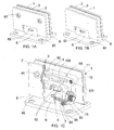
- FIG. 1A is a perspective view of a hinge for a glass door of an example which does not form part of the invention but represents useful background art.
- FIG. 1B is a perspective view, looking from another perspective, of the hinge for the glass door of the example of FIG. 1A .
- FIG. 1C is a perspective view, partly broken away, of the hinge for the glass door of the example of FIG. 1A ..
- FIG. 1D is an exploded perspective view of the hinge for the glass door of the example of FIG. 1A .
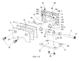
- FIG. 2A is a perspective view, partly broken away, of a hinge for a glass door of a first example according to the present invention.
- FIG. 2B is an exploded perspective view of the hinge for the glass door of the first example according to the present invention.
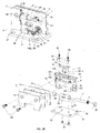
- FIG. 3A is a perspective view, partly broken away, of a hinge for a glass door of another example which does not form part of the invention.
- FIG. 3B is an exploded perspective view of the hinge for the glass door of the example of FIG. 3A .
- FIG. 4A is a perspective view, partly broken away, of a hinge for a glass door of a second example according to the present invention.
- FIG. 4B is an exploded perspective view of the hinge for the glass door of the second example according to the present invention.
- FIGs. 1A-1D an example which does not form part of the invention but represents useful background art is described as below.
- a hinge for a glass door comprises a first clamp member 1, a second clamp member 2, two gasket 3, a leaf spring 4, a positioning member 5, a pivot bracket 6, a pivot pin 7 and a mounting base 8.
- the first clamp member 1 has a clamp plate 11 and a connecting block 12 interconnected.
- the clamp plate 11 has a platelike structure.
- the connecting block 12 is smaller in diameter than the clamp plate 11 and is extending backwards from the back surface of the clamp plate 11.
- a first recess 13 is defined in the bottom end of the clamp plate 11 and the connecting block 12.
- the first recess 13 has a pair of pivot hole 123 in the two side surfaces thereof respectively.
- Two threaded clamp holes 121 are defined in the back surface of the top portion of the connecting block 12.
- a "T"-shaped spring slot 124 is defined between the threaded clamp holes 121 in the back surface of the top portion of the connecting block 12.
- a mounting hole 127 and a pressing hole 128 are defined in the top surface of the connecting block 12 corresponding to the two ends of the spring slot 124 and communicating with the spring slot 124.
- the mounting hole 127 passes through the top and bottom wall of the spring slot 124.
- the pressing hole 128 only passes through only the top wall of the spring slot 124.
- a roller receiving hole 125 is defined in the middle of the bottom surface of the spring slot 124, passing through the portion of the connecting block 12 below the spring slot 124, communicating with the recess 122.
- a rectangular hole 122 is defined in the back surface of the connecting block 12, below the two ends of the spring slot 124 and above the first recess 13, which is provide the economy of manufacture material.
- the second clamp member 2 is a clamp plate which has the same size of the first clamp member 1.
- a second recess 22 is defined in the bottom of the second clamp member 2 corresponding to and communicating with the first recess 13 of the first clamp member 1.
- a through hole 21 is defined in the second clamp member 2 corresponding to the threaded clamp hole 121 of the connecting block 12.
- the second clamp member 2 is fastened on the connecting block 12 of the first clamp member 1 by a bolt 91 passing through the through hole 21 and screwing into the threaded clamp hole 121.
- the bolt 91 use an allen countersunk head screw.
- the gaskets 3 are made of nylon.
- the gasket 3 has the similar shape and size with the clamp plate 11 of the first clamp member 1 and second clamp member 2.
- the gasket 3 has a notch 31 corresponding to the connecting block 12 of the first clamp member 1.
- the gaskets 3 are mounted around the connecting block 12 respectively adjacent to the clamp plate 11 and the second clamp member 2.
- a glass pane (not shown) can be clamped between the clamp plate 11 of the first clamp member 1 and the second clamp member 2 of the hinge after being notched out to receive the connecting block 12 of the first clamp member 1.
- Two gaskets 3 are mounted between the glass pane and the clamp plate 11, the second clamp member 2 respectively.
- the hinge is mounted on the glass pane.
- the leaf spring 4 is received in the spring slot 124 of the connecting block 12 of the first clamp member 1.
- a spring-mounting hole 42 is defined in one end of the leaf spring 4 corresponding to the mounting hole 127 of the connecting block 12.
- a bolt 93 screws into the pressing hole 128 and presses the other end of the leaf spring 4.
- the bolt 92 use an allen sunk screw
- the bolt 93 use a holding screw.
- the positioning member 5 has a connecting post 51, a roller bracket 52 and a roller 53.
- the connecting post 51 corresponds with the roller receiving hole 125 of the connecting block 12.
- the roller bracket 52 extends downwards from the connecting post 51.
- the roller 53 is hinged to the roller bracket 52. The bottom of the roller 53 passes through the roller receiving hole 125 into the first recess 13 by the press of the leaf spring 4.
- the pivot bracket 6 has a half-cylindrical top portion and a cuboid bottom portion.
- the pivot bracket 6 is received in the first recess 13 of the first clamp member 1 and the second recess 22 of the second clamp member 2.
- the cylindrical surface of the pivot bracket 6 is pressed against the roller 53.
- the pivot bracket 6 has a bore 61.
- Two bushings 63 are mounted respectively in the two ends of the bore 61.
- the pivot bracket 6 has three positioning slot 62 at intervals of 90 degrees, i.e in the 9, 12, 3 o'clock position, on the cylindrical surface.
- the pivot bracket 6 has two bracket mounting holes 64 on the bottom thereof.
- a gear 71 is defined on one end of the pivot pin 7.
- the connecting block 12 has a pair of pivot holes 123 on two side surface of the recess 13 and a gear ring (not shown) on the side surface of each of the pivot holes 123 respectively.
- the gear 71 goes into mesh with the gear ring to prevent the rotation of the pivot pin 7 relative to the first clamp member 1 and the glass door, i.e. the second clamp member 2, the first clamp member 1 and the glass door pane move at the same time.
- the cylindrical out surface of the pivot bracket 6 is urged by the roller 53.
- the roller 53 will inserted into the three positioning slots 62 in the proper order, i.e locate at the inwards opened position, the closed position and the outwards opened position.
- Two through holes 81 are defined in the mounting base 8 corresponding to the bracket mounting holes 64 in the pivot bracket 6.
- the pivot bracket 6 is fastened to the mounting base 8 by a plurality of bolts screwing into the through holes 81 and the bracket mounting holes 64.
- the mounting base 8 is also fastened to the doorframe by four bolts screwing into four through holes 82 in the corners of the base 8 and the holes in the doorframe.
- FIGs.2A-2B a first preferred embodiment of the hinge for the glass door of the present invention is schematically depicted.
- the components thereof same as or similar to those of the example in FIGs. 1A-1D use the same numerals.
- the second preferred embodiment differs from the example of FIGs 1A-1D only as follows:
- the leaf spring 4 has a through roller-mounting hole 41 in the middle thereof corresponding to the roller receiving hole 125 of the connecting block 12.
- a spring-mounting hole 54 is defined in the top surface of the connecting post 51 of the positioning member 5 corresponding to the roller-mounting hole 41.
- the leaf spring 4 is connected to the positioning member 5 by a bolt 94 screwing into the roller-mounting hole 41 and the spring-mounting hole 54 respectively.
- the bolt 94 uses a cross recessed countersunk head screw.
- a through hole 126 is defined in the top surface of the connecting block 12 corresponding to the roller receiving hole 125 and communicating with the spring slot 124 to provide a passage for the bolt 94.
- Two pressing holes 128 are defined in the top surface of the connecting block 12 communicating with the spring slot 124. Two ends of leaf spring 4 do not have the spring-mounting hole 42.
- the leaf spring 4 is mounted in the spring slot 124 by the bolts 93 screwing into the pressing holes 128 and pressing the two ends of the leaf spring 4 securely.
- the bolts 93 use holding screws.
- FIGs.3A-3B another example of the hinge for the glass door which does not form part of the invention is schematically depicted.
- the components thereof same as or similar to those of the example of FIGs. 1A-1D use the same numerals.
- FIGs. 3A-3B differs from the example of FIGs 1A-1D only as follows:
- the connecting block 12 has a notch in the top thereof and a fastening panel 14 covering the open side of the notch to form the spring slot 124.
- Two threaded holes 127 are defined in the bottom surface of the spring slot 124 of the connecting block 12.
- the fastening panel 14 has two through holes 141 corresponding to the holes 127 respectively.
- Each end of the leaf spring 4 has a spring-mounting hole 42 respectively corresponding to the holes 127.
- FIGs.4A-4B a second preferred embodiment of the hinge for the glass door of the present invention is schematically depicted.
- the components thereof same as or similar to those of the example of FIGs. 1A-1D use the same numerals.
- the fourth preferred embodiment differs from the example of FIGs. 3A-3B only as follows:
- a roller-mounting hole 41 is defined in the middle portion of the leaf spring 4 corresponding to the roller receiving hole 125 of the connecting block 12.
- a spring-mounting hole 54 is defined in the top surface of the connecting post 51 of the positioning member 5 corresponding to the roller-mounting hole 41.
- the leaf spring 4 is connected to the positioning member 5 by a bolt 94 screwing into the roller-mounting hole 41 and the spring-mounting hole 54.
- the bolt 94 use a cross recessed countersunk head screw.
Landscapes
- Engineering & Computer Science (AREA)
- Mechanical Engineering (AREA)
- Hinges (AREA)
- Surface Treatment Of Glass (AREA)
- Closing And Opening Devices For Wings, And Checks For Wings (AREA)
- Hinge Accessories (AREA)
Claims (8)
- Charnière pour une porte vitrée comprenant : un premier élément d'attache (1) ayant une première partie en retrait (13) ; une fente de ressort (124) dans la surface intérieure dudit premier élément d'attache (1) ; et un trou de réception de rouleau (125) dans la surface latérale de ladite fente de ressort (124), communiquant avec ladite première partie en retrait (13) ; un second élément d'attache (2), fixé audit premier élément d'attache pour définir un espace de réception de panneau vitré, ayant une seconde partie en retrait (22) correspondant à ladite première partie en retrait (13) ; un ressort (4), reçu dans ladite fente de ressort (124) dudit premier élément d'attache (1) ; un élément de positionnement (5) avec un rouleau (53), ledit élément de positionnement (5) étant reçu dans ledit trou de réception de rouleau (125) et relié audit ressort (4), l'extrémité dudit élément de positionnement (5) passant à travers ledit trou de réception de rouleau (125) dans ladite première partie en retrait (13) par la poussée dudit ressort (4) ; un support pivotant (6), monté sur un chambranle, reçu dans ladite première partie en retrait (13) et ladite seconde partie en retrait (22), ayant une surface extérieure cylindrique correspondant audit élément de positionnement (5) et pressée contre ledit élément de positionnement (5), ayant une pluralité de fentes de positionnement (62) sur ladite surface extérieure cylindrique correspondant audit rouleau (53) dudit élément de positionnement (5) ; et un axe d'articulation (7), par lequel ledit premier élément d'attache (1) est articulé audit support pivotant (6), caractérisé en ce que ledit ressort est un ressort à lames (4) et en ce qu'un trou de montage de rouleau (41) est défini dans ledit ressort à lames (4) et qu'un trou de montage de ressort (54) est défini dans ledit élément de positionnement (5) correspondant audit trou de montage de rouleau (41), ledit ressort à lames (4) et ledit élément de positionnement (5) étant interconnectés par un boulon (94) se vissant respectivement dans ledit trou de montage de rouleau (41) et ledit trou de montage de ressort (54).
- Charnière selon la revendication 1, dans laquelle un engrenage (71) est défini sur une extrémité dudit axe d'articulation (7), ledit premier élément d'attache (1) ayant un couple de trous d'axe (123) dans les deux surfaces latérales de ladite première partie en retrait (13) et une bague dentée dans ledit trou d'axe (123), ledit engrenage (71) se mettant en prise avec ladite bague dentée lorsque ledit premier élément d'attache (1) est articulé audit support pivotant (6) par ledit axe d'articulation (7) s'étendant à travers ce dernier.
- Charnière selon la revendication 1, dans laquelle ledit premier élément d'attache (1) a une encoche et un panneau de fixation (14) recouvrant le côté ouvert de ladite encoche pour former ladite fente de ressort (124).
- Charnière selon la revendication 1, dans laquelle un trou traversant (126) est défini dans la surface latérale de ladite fente de ressort (124) correspondant audit trou de réception de rouleau (125).
- Charnière selon la revendication 1, dans laquelle ledit élément de positionnement (5) est pressé et poussé par ledit ressort à lames (4).
- Charnière selon la revendication 1, dans lequel ledit élément de positionnement (5) comprend : un montant de connexion (51) ; un support de rouleau (52) s'étendant à partir dudit montant de connexion (51) ; et un rouleau (53), articulé audit support de rouleau (52), dont l'extrémité passe à travers ledit trou de réception de rouleau (125) dans ladite première partie en retrait (13) par la poussée dudit ressort à lames (4).
- Charnière selon la revendication 1, dans laquelle ledit support pivotant (6) a trois dites fentes de positionnement (62) à des intervalles de 90 degrés sur ladite surface extérieure cylindrique.
- Charnière selon la revendication 1, comprenant en outre une base de montage (8) fixée sur ledit support pivotant (6) et solidement montée sur ledit chambranle.
Priority Applications (1)
| Application Number | Priority Date | Filing Date | Title |
|---|---|---|---|
| PL08167979T PL2055878T3 (pl) | 2007-10-31 | 2008-10-30 | Zawiasy do drzwi szklanych |
Applications Claiming Priority (1)
| Application Number | Priority Date | Filing Date | Title |
|---|---|---|---|
| CNU2007203021039U CN201110071Y (zh) | 2007-10-31 | 2007-10-31 | 玻璃门合页 |
Publications (2)
| Publication Number | Publication Date |
|---|---|
| EP2055878A1 EP2055878A1 (fr) | 2009-05-06 |
| EP2055878B1 true EP2055878B1 (fr) | 2011-05-04 |
Family
ID=39894600
Family Applications (1)
| Application Number | Title | Priority Date | Filing Date |
|---|---|---|---|
| EP08167979A Not-in-force EP2055878B1 (fr) | 2007-10-31 | 2008-10-30 | Charnière pour porte vitrée |
Country Status (7)
| Country | Link |
|---|---|
| US (1) | US7917994B2 (fr) |
| EP (1) | EP2055878B1 (fr) |
| CN (1) | CN201110071Y (fr) |
| AT (1) | ATE508244T1 (fr) |
| DE (1) | DE602008006650D1 (fr) |
| MY (1) | MY149274A (fr) |
| PL (1) | PL2055878T3 (fr) |
Families Citing this family (24)
| Publication number | Priority date | Publication date | Assignee | Title |
|---|---|---|---|---|
| US8046873B2 (en) * | 2008-09-22 | 2011-11-01 | Door & Window Hardware Co | Spider hinge for a frameless glass door |
| TWI359227B (en) * | 2009-02-17 | 2012-03-01 | Combao Internat Co Ltd | Hinge device of glass door |
| DE102009022803B4 (de) * | 2009-05-27 | 2017-08-03 | Dormakaba Deutschland Gmbh | Dreiteiliger Universaltürbeschlag |
| DE102009034740A1 (de) * | 2009-07-24 | 2011-01-27 | Dorma Gmbh + Co. Kg | Drehbar gelagerte Tür mit einem Band |
| NL2005520C2 (nl) * | 2010-10-14 | 2011-09-13 | Estem B V | Scharnier voor een paneeldeur, in het bijzonder voor een koelmeubel. |
| TW201326527A (zh) * | 2011-12-21 | 2013-07-01 | Gang Gwo Ind Co Ltd | 油壓鉸鍊 |
| CN102562734B (zh) * | 2012-02-20 | 2013-08-07 | 无锡康贝电子设备有限公司 | 机柜用固定连接件结构 |
| US20140068893A1 (en) * | 2012-09-07 | 2014-03-13 | E Tai Enterprise Co., Ltd. | Door damping apparatus and manufacturing method thereof |
| US9127876B2 (en) * | 2013-03-14 | 2015-09-08 | Electrolux Home Products, Inc. | Snap off center flipper mullion |
| CA2908304A1 (fr) * | 2013-04-12 | 2014-10-16 | In & Tec S.R.L. | Charniere pour le mouvement de rotation regule d'une porte, en particulier d'une porte en verre |
| US20160076292A1 (en) * | 2013-04-15 | 2016-03-17 | Michael Christopher Stuart | Hinge |
| US9297191B1 (en) * | 2014-09-30 | 2016-03-29 | Wei-Chu Chen | Hinge |
| EP3029241A1 (fr) * | 2014-12-04 | 2016-06-08 | DORMA Deutschland GmbH | Ferrure d'angle à force de serrage accrue |
| GB2538039A (en) * | 2015-02-04 | 2016-11-09 | Kohler Mira Ltd | Hinge |
| GB2585134B (en) * | 2015-02-04 | 2021-06-16 | Kohler Mira Ltd | Hinge |
| CA162015S (en) * | 2015-04-21 | 2017-05-19 | Fleurco Products Inc | Shower door assembly |
| CN105041082B (zh) * | 2015-08-19 | 2017-06-16 | 伍志勇 | 用于家具的可转动定位铰链结构 |
| ITUB20153873A1 (it) * | 2015-09-24 | 2017-03-24 | Mgt Ind S R L | Cerniera perfezionata per ante girevoli, specialmente di cabine doccia |
| CA3014701C (fr) | 2016-02-17 | 2025-05-06 | Polaris IP Pty Ltd | Charnière |
| DE202016003803U1 (de) * | 2016-06-17 | 2017-09-20 | Dieter Ramsauer | Scharniersystem |
| TWI602979B (zh) * | 2017-02-15 | 2017-10-21 | Waterson Corp | Multi-purpose hinge device |
| US10329818B2 (en) * | 2017-08-30 | 2019-06-25 | Fujian Zihe Sanitary Ware Technology Co., Ltd. | Hinge assembly |
| JP7469236B2 (ja) * | 2019-08-30 | 2024-04-16 | スガツネ工業株式会社 | 1軸ヒンジ |
| US12422062B2 (en) * | 2023-09-29 | 2025-09-23 | Wintec Arrowmaker, Inc. | Hinge assembly |
Family Cites Families (14)
| Publication number | Priority date | Publication date | Assignee | Title |
|---|---|---|---|---|
| US2394014A (en) | 1940-08-02 | 1946-02-05 | Rudolph I Schonitzer | Combined door-hinging, door-checking, and door-holding device |
| DE4239359A1 (de) * | 1992-11-24 | 1994-05-26 | Karl Loggen | Gelenkband |
| FR2745323B1 (fr) * | 1996-02-28 | 1998-05-07 | Stremler | Charniere pour porte ou panneau notamment pour panneau en verre |
| FR2761398B1 (fr) * | 1997-03-27 | 1999-06-04 | Stremler | Charniere pour portillon ou panneau pivotant, notamment pour panneau en verre |
| US5867871A (en) * | 1997-11-11 | 1999-02-09 | Tasman; Randy | Outwardly swinging shower door hinge having a concealed knuckle |
| US6481055B2 (en) * | 2001-04-10 | 2002-11-19 | Ko Ming Cheng | Pivotal device for a frameless glass door |
| DE20109588U1 (de) * | 2001-06-08 | 2001-08-30 | Dah Ling Hardware Co., Ltd., Chang Hwa | Französische Türpositioniereinrichtung |
| US6704966B1 (en) * | 2002-10-30 | 2004-03-16 | Chin-Min Kao | Waterproof hinge structure for glass door |
| DE10313962A1 (de) * | 2003-03-27 | 2004-10-07 | Dorma Gmbh + Co. Kg | Band, insbesondere für Dusch- und/oder Glastüren |
| US6766561B1 (en) * | 2003-03-28 | 2004-07-27 | Ko-Ming Cheng | Frameless glass door hinge |
| US7010832B2 (en) * | 2003-10-02 | 2006-03-14 | Mei Li Chen | Angular adjustment arrangement of side pivot hinge |
| US20050125949A1 (en) * | 2003-12-10 | 2005-06-16 | Fang Tsan Co., Ltd. | Adjustable hinge for assembling a non-frame plate glass of a bathroom |
| EP1640539B1 (fr) | 2004-09-22 | 2008-03-19 | Metalglas S.r.l. | Charnière, en particulier pour porte en verre |
| FR2907488B1 (fr) * | 2006-10-23 | 2011-04-22 | Adler Sa | Charniere a rappel automatique. |
-
2007
- 2007-10-31 CN CNU2007203021039U patent/CN201110071Y/zh not_active Expired - Lifetime
-
2008
- 2008-10-30 DE DE602008006650T patent/DE602008006650D1/de active Active
- 2008-10-30 US US12/289,561 patent/US7917994B2/en not_active Expired - Fee Related
- 2008-10-30 AT AT08167979T patent/ATE508244T1/de not_active IP Right Cessation
- 2008-10-30 EP EP08167979A patent/EP2055878B1/fr not_active Not-in-force
- 2008-10-30 PL PL08167979T patent/PL2055878T3/pl unknown
- 2008-10-30 MY MYPI20084327A patent/MY149274A/en unknown
Also Published As
| Publication number | Publication date |
|---|---|
| US20090106937A1 (en) | 2009-04-30 |
| MY149274A (en) | 2013-08-15 |
| ATE508244T1 (de) | 2011-05-15 |
| CN201110071Y (zh) | 2008-09-03 |
| EP2055878A1 (fr) | 2009-05-06 |
| PL2055878T3 (pl) | 2011-10-31 |
| US7917994B2 (en) | 2011-04-05 |
| DE602008006650D1 (de) | 2011-06-16 |
Similar Documents
| Publication | Publication Date | Title |
|---|---|---|
| EP2055878B1 (fr) | Charnière pour porte vitrée | |
| US7305797B2 (en) | Door-closing assembly of frameless glass door | |
| US6560821B2 (en) | Glass door hinge | |
| US10337229B2 (en) | Hinge | |
| US7188390B2 (en) | Adjustable hinge for a glass door | |
| US5867869A (en) | Pressure hinge device for glass door or panel | |
| US7107723B2 (en) | Adjustable automatic positioning hinge for glass doors | |
| US8381355B2 (en) | Adjustable hinge | |
| US5297313A (en) | Pivot hinge assembly for glass structures | |
| CN114382341A (zh) | 无装饰盖门窗把手 | |
| KR200410197Y1 (ko) | 댐퍼가 구비된 도어힌지 | |
| AU2004221739A1 (en) | Fitting | |
| EP3680432B1 (fr) | Charnière réglable 3d pour porte ou fenêtre | |
| US20080083088A1 (en) | Door hinge structure | |
| CA3020835C (fr) | Bras de chargement d'extremite | |
| GB2443020A (en) | Door hinge with spring having adjustable resilience | |
| WO2004067888A1 (fr) | Fiche reglable tridirectionnelle | |
| WO2020245731A1 (fr) | Charnière pour le mouvement rotatif d'une porte, d'un battant ou similaire et système de fixation de cette dernière à une structure de support fixe | |
| JPH04176984A (ja) | 自動閉戸機構を備えた蝶番 | |
| US4139925A (en) | Door hinge, particularly for refrigerators | |
| US7533443B2 (en) | Device for blocking open the door of a housing | |
| CN223497741U (zh) | 闭门器的快调式滑轨结构 | |
| JP6746049B1 (ja) | ドアストッパー | |
| JPH04336189A (ja) | 自動閉戸機構を備えた蝶番 | |
| EP4361383A1 (fr) | Support pour l'installation de dispositifs d'ouverture et de fermeture dans des cylindres de serrure |
Legal Events
| Date | Code | Title | Description |
|---|---|---|---|
| PUAI | Public reference made under article 153(3) epc to a published international application that has entered the european phase |
Free format text: ORIGINAL CODE: 0009012 |
|
| 17P | Request for examination filed |
Effective date: 20081030 |
|
| AK | Designated contracting states |
Kind code of ref document: A1 Designated state(s): AT BE BG CH CY CZ DE DK EE ES FI FR GB GR HR HU IE IS IT LI LT LU LV MC MT NL NO PL PT RO SE SI SK TR |
|
| AX | Request for extension of the european patent |
Extension state: AL BA MK RS |
|
| AKX | Designation fees paid |
Designated state(s): AT BE BG CH CY CZ DE DK EE ES FI FR GB GR HR HU IE IS IT LI LT LU LV MC MT NL NO PL PT RO SE SI SK TR |
|
| 17Q | First examination report despatched |
Effective date: 20100113 |
|
| GRAP | Despatch of communication of intention to grant a patent |
Free format text: ORIGINAL CODE: EPIDOSNIGR1 |
|
| GRAS | Grant fee paid |
Free format text: ORIGINAL CODE: EPIDOSNIGR3 |
|
| GRAA | (expected) grant |
Free format text: ORIGINAL CODE: 0009210 |
|
| AK | Designated contracting states |
Kind code of ref document: B1 Designated state(s): AT BE BG CH CY CZ DE DK EE ES FI FR GB GR HR HU IE IS IT LI LT LU LV MC MT NL NO PL PT RO SE SI SK TR |
|
| REG | Reference to a national code |
Ref country code: GB Ref legal event code: FG4D |
|
| REG | Reference to a national code |
Ref country code: CH Ref legal event code: EP |
|
| REG | Reference to a national code |
Ref country code: IE Ref legal event code: FG4D |
|
| REF | Corresponds to: |
Ref document number: 602008006650 Country of ref document: DE Date of ref document: 20110616 Kind code of ref document: P |
|
| REG | Reference to a national code |
Ref country code: DE Ref legal event code: R096 Ref document number: 602008006650 Country of ref document: DE Effective date: 20110616 |
|
| REG | Reference to a national code |
Ref country code: SE Ref legal event code: TRGR |
|
| REG | Reference to a national code |
Ref country code: NL Ref legal event code: VDEP Effective date: 20110504 |
|
| PG25 | Lapsed in a contracting state [announced via postgrant information from national office to epo] |
Ref country code: NO Free format text: LAPSE BECAUSE OF FAILURE TO SUBMIT A TRANSLATION OF THE DESCRIPTION OR TO PAY THE FEE WITHIN THE PRESCRIBED TIME-LIMIT Effective date: 20110804 Ref country code: LT Free format text: LAPSE BECAUSE OF FAILURE TO SUBMIT A TRANSLATION OF THE DESCRIPTION OR TO PAY THE FEE WITHIN THE PRESCRIBED TIME-LIMIT Effective date: 20110504 Ref country code: PT Free format text: LAPSE BECAUSE OF FAILURE TO SUBMIT A TRANSLATION OF THE DESCRIPTION OR TO PAY THE FEE WITHIN THE PRESCRIBED TIME-LIMIT Effective date: 20110905 |
|
| REG | Reference to a national code |
Ref country code: PL Ref legal event code: T3 |
|
| PG25 | Lapsed in a contracting state [announced via postgrant information from national office to epo] |
Ref country code: CY Free format text: LAPSE BECAUSE OF FAILURE TO SUBMIT A TRANSLATION OF THE DESCRIPTION OR TO PAY THE FEE WITHIN THE PRESCRIBED TIME-LIMIT Effective date: 20110504 Ref country code: GR Free format text: LAPSE BECAUSE OF FAILURE TO SUBMIT A TRANSLATION OF THE DESCRIPTION OR TO PAY THE FEE WITHIN THE PRESCRIBED TIME-LIMIT Effective date: 20110805 Ref country code: BE Free format text: LAPSE BECAUSE OF FAILURE TO SUBMIT A TRANSLATION OF THE DESCRIPTION OR TO PAY THE FEE WITHIN THE PRESCRIBED TIME-LIMIT Effective date: 20110504 Ref country code: AT Free format text: LAPSE BECAUSE OF FAILURE TO SUBMIT A TRANSLATION OF THE DESCRIPTION OR TO PAY THE FEE WITHIN THE PRESCRIBED TIME-LIMIT Effective date: 20110504 Ref country code: SI Free format text: LAPSE BECAUSE OF FAILURE TO SUBMIT A TRANSLATION OF THE DESCRIPTION OR TO PAY THE FEE WITHIN THE PRESCRIBED TIME-LIMIT Effective date: 20110504 Ref country code: FI Free format text: LAPSE BECAUSE OF FAILURE TO SUBMIT A TRANSLATION OF THE DESCRIPTION OR TO PAY THE FEE WITHIN THE PRESCRIBED TIME-LIMIT Effective date: 20110504 Ref country code: IS Free format text: LAPSE BECAUSE OF FAILURE TO SUBMIT A TRANSLATION OF THE DESCRIPTION OR TO PAY THE FEE WITHIN THE PRESCRIBED TIME-LIMIT Effective date: 20110904 Ref country code: LV Free format text: LAPSE BECAUSE OF FAILURE TO SUBMIT A TRANSLATION OF THE DESCRIPTION OR TO PAY THE FEE WITHIN THE PRESCRIBED TIME-LIMIT Effective date: 20110504 Ref country code: ES Free format text: LAPSE BECAUSE OF FAILURE TO SUBMIT A TRANSLATION OF THE DESCRIPTION OR TO PAY THE FEE WITHIN THE PRESCRIBED TIME-LIMIT Effective date: 20110815 |
|
| PG25 | Lapsed in a contracting state [announced via postgrant information from national office to epo] |
Ref country code: NL Free format text: LAPSE BECAUSE OF FAILURE TO SUBMIT A TRANSLATION OF THE DESCRIPTION OR TO PAY THE FEE WITHIN THE PRESCRIBED TIME-LIMIT Effective date: 20110504 |
|
| PG25 | Lapsed in a contracting state [announced via postgrant information from national office to epo] |
Ref country code: CZ Free format text: LAPSE BECAUSE OF FAILURE TO SUBMIT A TRANSLATION OF THE DESCRIPTION OR TO PAY THE FEE WITHIN THE PRESCRIBED TIME-LIMIT Effective date: 20110504 Ref country code: EE Free format text: LAPSE BECAUSE OF FAILURE TO SUBMIT A TRANSLATION OF THE DESCRIPTION OR TO PAY THE FEE WITHIN THE PRESCRIBED TIME-LIMIT Effective date: 20110504 |
|
| REG | Reference to a national code |
Ref country code: FR Ref legal event code: TP Owner name: GUANGDONG KIN LONG HARDWARE PRODUCTS CO., LTD., CN Effective date: 20120120 |
|
| PG25 | Lapsed in a contracting state [announced via postgrant information from national office to epo] |
Ref country code: SK Free format text: LAPSE BECAUSE OF FAILURE TO SUBMIT A TRANSLATION OF THE DESCRIPTION OR TO PAY THE FEE WITHIN THE PRESCRIBED TIME-LIMIT Effective date: 20110504 Ref country code: DK Free format text: LAPSE BECAUSE OF FAILURE TO SUBMIT A TRANSLATION OF THE DESCRIPTION OR TO PAY THE FEE WITHIN THE PRESCRIBED TIME-LIMIT Effective date: 20110504 Ref country code: RO Free format text: LAPSE BECAUSE OF FAILURE TO SUBMIT A TRANSLATION OF THE DESCRIPTION OR TO PAY THE FEE WITHIN THE PRESCRIBED TIME-LIMIT Effective date: 20110504 |
|
| PLBE | No opposition filed within time limit |
Free format text: ORIGINAL CODE: 0009261 |
|
| STAA | Information on the status of an ep patent application or granted ep patent |
Free format text: STATUS: NO OPPOSITION FILED WITHIN TIME LIMIT |
|
| REG | Reference to a national code |
Ref country code: GB Ref legal event code: 732E Free format text: REGISTERED BETWEEN 20120301 AND 20120307 |
|
| 26N | No opposition filed |
Effective date: 20120207 |
|
| REG | Reference to a national code |
Ref country code: FR Ref legal event code: RM Effective date: 20120410 |
|
| PG25 | Lapsed in a contracting state [announced via postgrant information from national office to epo] |
Ref country code: MC Free format text: LAPSE BECAUSE OF NON-PAYMENT OF DUE FEES Effective date: 20111031 Ref country code: HR Free format text: LAPSE BECAUSE OF FAILURE TO SUBMIT A TRANSLATION OF THE DESCRIPTION OR TO PAY THE FEE WITHIN THE PRESCRIBED TIME-LIMIT Effective date: 20111123 |
|
| REG | Reference to a national code |
Ref country code: DE Ref legal event code: R097 Ref document number: 602008006650 Country of ref document: DE Effective date: 20120207 |
|
| REG | Reference to a national code |
Ref country code: IE Ref legal event code: MM4A |
|
| REG | Reference to a national code |
Ref country code: DE Ref legal event code: R082 Ref document number: 602008006650 Country of ref document: DE Representative=s name: MICHALSKI HUETTERMANN & PARTNER PATENTANWAELTE, DE |
|
| REG | Reference to a national code |
Ref country code: DE Ref legal event code: R082 Ref document number: 602008006650 Country of ref document: DE Representative=s name: MICHALSKI HUETTERMANN & PARTNER PATENTANWAELTE, DE Effective date: 20120808 Ref country code: DE Ref legal event code: R081 Ref document number: 602008006650 Country of ref document: DE Owner name: GUANGDONG KIN LONG HARDWARE PRODUCTS CO. LTD., CN Free format text: FORMER OWNER: BAOKUN BAI, DONGGUAN CITY, CN Effective date: 20120808 Ref country code: DE Ref legal event code: R081 Ref document number: 602008006650 Country of ref document: DE Owner name: GUANGDONG KIN LONG HARDWARE PRODUCTS CO. LTD., CN Free format text: FORMER OWNER: BAI, BAOKUN, DONGGUAN CITY, GUANGDONG, CN Effective date: 20120808 |
|
| PG25 | Lapsed in a contracting state [announced via postgrant information from national office to epo] |
Ref country code: IE Free format text: LAPSE BECAUSE OF NON-PAYMENT OF DUE FEES Effective date: 20111030 |
|
| PG25 | Lapsed in a contracting state [announced via postgrant information from national office to epo] |
Ref country code: MT Free format text: LAPSE BECAUSE OF FAILURE TO SUBMIT A TRANSLATION OF THE DESCRIPTION OR TO PAY THE FEE WITHIN THE PRESCRIBED TIME-LIMIT Effective date: 20110504 |
|
| PG25 | Lapsed in a contracting state [announced via postgrant information from national office to epo] |
Ref country code: LU Free format text: LAPSE BECAUSE OF NON-PAYMENT OF DUE FEES Effective date: 20111030 |
|
| REG | Reference to a national code |
Ref country code: CH Ref legal event code: PL |
|
| PG25 | Lapsed in a contracting state [announced via postgrant information from national office to epo] |
Ref country code: BG Free format text: LAPSE BECAUSE OF FAILURE TO SUBMIT A TRANSLATION OF THE DESCRIPTION OR TO PAY THE FEE WITHIN THE PRESCRIBED TIME-LIMIT Effective date: 20110804 |
|
| PG25 | Lapsed in a contracting state [announced via postgrant information from national office to epo] |
Ref country code: CH Free format text: LAPSE BECAUSE OF NON-PAYMENT OF DUE FEES Effective date: 20121031 Ref country code: LI Free format text: LAPSE BECAUSE OF NON-PAYMENT OF DUE FEES Effective date: 20121031 |
|
| PG25 | Lapsed in a contracting state [announced via postgrant information from national office to epo] |
Ref country code: HU Free format text: LAPSE BECAUSE OF FAILURE TO SUBMIT A TRANSLATION OF THE DESCRIPTION OR TO PAY THE FEE WITHIN THE PRESCRIBED TIME-LIMIT Effective date: 20110504 |
|
| PG25 | Lapsed in a contracting state [announced via postgrant information from national office to epo] |
Ref country code: HR Free format text: LAPSE BECAUSE OF FAILURE TO SUBMIT A TRANSLATION OF THE DESCRIPTION OR TO PAY THE FEE WITHIN THE PRESCRIBED TIME-LIMIT Effective date: 20110504 |
|
| REG | Reference to a national code |
Ref country code: FR Ref legal event code: PLFP Year of fee payment: 8 |
|
| REG | Reference to a national code |
Ref country code: FR Ref legal event code: PLFP Year of fee payment: 9 |
|
| REG | Reference to a national code |
Ref country code: FR Ref legal event code: PLFP Year of fee payment: 10 |
|
| REG | Reference to a national code |
Ref country code: FR Ref legal event code: PLFP Year of fee payment: 11 |
|
| PGFP | Annual fee paid to national office [announced via postgrant information from national office to epo] |
Ref country code: PL Payment date: 20210920 Year of fee payment: 14 |
|
| PGFP | Annual fee paid to national office [announced via postgrant information from national office to epo] |
Ref country code: GB Payment date: 20211022 Year of fee payment: 14 Ref country code: SE Payment date: 20211020 Year of fee payment: 14 Ref country code: TR Payment date: 20211027 Year of fee payment: 14 Ref country code: DE Payment date: 20211020 Year of fee payment: 14 |
|
| PGFP | Annual fee paid to national office [announced via postgrant information from national office to epo] |
Ref country code: IT Payment date: 20211028 Year of fee payment: 14 Ref country code: FR Payment date: 20211021 Year of fee payment: 14 |
|
| REG | Reference to a national code |
Ref country code: DE Ref legal event code: R119 Ref document number: 602008006650 Country of ref document: DE |
|
| REG | Reference to a national code |
Ref country code: SE Ref legal event code: EUG |
|
| GBPC | Gb: european patent ceased through non-payment of renewal fee |
Effective date: 20221030 |
|
| PG25 | Lapsed in a contracting state [announced via postgrant information from national office to epo] |
Ref country code: FR Free format text: LAPSE BECAUSE OF NON-PAYMENT OF DUE FEES Effective date: 20221031 Ref country code: DE Free format text: LAPSE BECAUSE OF NON-PAYMENT OF DUE FEES Effective date: 20230503 |
|
| PG25 | Lapsed in a contracting state [announced via postgrant information from national office to epo] |
Ref country code: SE Free format text: LAPSE BECAUSE OF NON-PAYMENT OF DUE FEES Effective date: 20221031 |
|
| PG25 | Lapsed in a contracting state [announced via postgrant information from national office to epo] |
Ref country code: IT Free format text: LAPSE BECAUSE OF NON-PAYMENT OF DUE FEES Effective date: 20221030 Ref country code: GB Free format text: LAPSE BECAUSE OF NON-PAYMENT OF DUE FEES Effective date: 20221030 |
|
| PG25 | Lapsed in a contracting state [announced via postgrant information from national office to epo] |
Ref country code: PL Free format text: LAPSE BECAUSE OF NON-PAYMENT OF DUE FEES Effective date: 20221030 |
|
| PG25 | Lapsed in a contracting state [announced via postgrant information from national office to epo] |
Ref country code: TR Free format text: LAPSE BECAUSE OF NON-PAYMENT OF DUE FEES Effective date: 20221030 |