EP2055885A2 - Verbindungsstück und Verbindung von Profilen mit diesem Stück - Google Patents
Verbindungsstück und Verbindung von Profilen mit diesem Stück Download PDFInfo
- Publication number
- EP2055885A2 EP2055885A2 EP08352025A EP08352025A EP2055885A2 EP 2055885 A2 EP2055885 A2 EP 2055885A2 EP 08352025 A EP08352025 A EP 08352025A EP 08352025 A EP08352025 A EP 08352025A EP 2055885 A2 EP2055885 A2 EP 2055885A2
- Authority
- EP
- European Patent Office
- Prior art keywords
- profile
- forming
- connecting piece
- extrados
- face
- Prior art date
- Legal status (The legal status is an assumption and is not a legal conclusion. Google has not performed a legal analysis and makes no representation as to the accuracy of the status listed.)
- Withdrawn
Links
- 238000010276 construction Methods 0.000 claims abstract description 40
- 238000002347 injection Methods 0.000 claims abstract description 26
- 239000007924 injection Substances 0.000 claims abstract description 26
- 239000003566 sealing material Substances 0.000 claims abstract description 5
- 238000000034 method Methods 0.000 claims abstract 3
- 238000007789 sealing Methods 0.000 claims description 19
- 239000000463 material Substances 0.000 claims description 15
- 238000005304 joining Methods 0.000 claims description 9
- 238000007373 indentation Methods 0.000 claims description 8
- 238000004026 adhesive bonding Methods 0.000 claims description 4
- 230000000740 bleeding effect Effects 0.000 claims 1
- 239000000853 adhesive Substances 0.000 abstract 1
- 230000001070 adhesive effect Effects 0.000 abstract 1
- 239000000565 sealant Substances 0.000 description 2
- 241001080024 Telles Species 0.000 description 1
- 239000000470 constituent Substances 0.000 description 1
- 238000004519 manufacturing process Methods 0.000 description 1
Images


Classifications
-
- E—FIXED CONSTRUCTIONS
- E06—DOORS, WINDOWS, SHUTTERS, OR ROLLER BLINDS IN GENERAL; LADDERS
- E06B—FIXED OR MOVABLE CLOSURES FOR OPENINGS IN BUILDINGS, VEHICLES, FENCES OR LIKE ENCLOSURES IN GENERAL, e.g. DOORS, WINDOWS, BLINDS, GATES
- E06B3/00—Window sashes, door leaves, or like elements for closing wall or like openings; Layout of fixed or moving closures, e.g. windows in wall or like openings; Features of rigidly-mounted outer frames relating to the mounting of wing frames
- E06B3/96—Corner joints or edge joints for windows, doors, or the like frames or wings
- E06B3/964—Corner joints or edge joints for windows, doors, or the like frames or wings using separate connection pieces, e.g. T-connection pieces
- E06B3/968—Corner joints or edge joints for windows, doors, or the like frames or wings using separate connection pieces, e.g. T-connection pieces characterised by the way the connecting pieces are fixed in or on the frame members
- E06B3/9687—Corner joints or edge joints for windows, doors, or the like frames or wings using separate connection pieces, e.g. T-connection pieces characterised by the way the connecting pieces are fixed in or on the frame members with screws blocking the connecting piece inside or on the frame member
-
- E—FIXED CONSTRUCTIONS
- E06—DOORS, WINDOWS, SHUTTERS, OR ROLLER BLINDS IN GENERAL; LADDERS
- E06B—FIXED OR MOVABLE CLOSURES FOR OPENINGS IN BUILDINGS, VEHICLES, FENCES OR LIKE ENCLOSURES IN GENERAL, e.g. DOORS, WINDOWS, BLINDS, GATES
- E06B3/00—Window sashes, door leaves, or like elements for closing wall or like openings; Layout of fixed or moving closures, e.g. windows in wall or like openings; Features of rigidly-mounted outer frames relating to the mounting of wing frames
- E06B3/96—Corner joints or edge joints for windows, doors, or the like frames or wings
- E06B3/9632—Corner joints or edge joints for windows, doors, or the like frames or wings between a jamb and the threshold or sill of window or door frames
-
- E—FIXED CONSTRUCTIONS
- E06—DOORS, WINDOWS, SHUTTERS, OR ROLLER BLINDS IN GENERAL; LADDERS
- E06B—FIXED OR MOVABLE CLOSURES FOR OPENINGS IN BUILDINGS, VEHICLES, FENCES OR LIKE ENCLOSURES IN GENERAL, e.g. DOORS, WINDOWS, BLINDS, GATES
- E06B3/00—Window sashes, door leaves, or like elements for closing wall or like openings; Layout of fixed or moving closures, e.g. windows in wall or like openings; Features of rigidly-mounted outer frames relating to the mounting of wing frames
- E06B3/96—Corner joints or edge joints for windows, doors, or the like frames or wings
- E06B3/964—Corner joints or edge joints for windows, doors, or the like frames or wings using separate connection pieces, e.g. T-connection pieces
- E06B3/9641—Corner joints or edge joints for windows, doors, or the like frames or wings using separate connection pieces, e.g. T-connection pieces part of which remains visible
-
- E—FIXED CONSTRUCTIONS
- E06—DOORS, WINDOWS, SHUTTERS, OR ROLLER BLINDS IN GENERAL; LADDERS
- E06B—FIXED OR MOVABLE CLOSURES FOR OPENINGS IN BUILDINGS, VEHICLES, FENCES OR LIKE ENCLOSURES IN GENERAL, e.g. DOORS, WINDOWS, BLINDS, GATES
- E06B3/00—Window sashes, door leaves, or like elements for closing wall or like openings; Layout of fixed or moving closures, e.g. windows in wall or like openings; Features of rigidly-mounted outer frames relating to the mounting of wing frames
- E06B3/96—Corner joints or edge joints for windows, doors, or the like frames or wings
- E06B3/964—Corner joints or edge joints for windows, doors, or the like frames or wings using separate connection pieces, e.g. T-connection pieces
- E06B3/9642—Butt type joints with at least one frame member cut off square; T-shape joints
-
- E—FIXED CONSTRUCTIONS
- E06—DOORS, WINDOWS, SHUTTERS, OR ROLLER BLINDS IN GENERAL; LADDERS
- E06B—FIXED OR MOVABLE CLOSURES FOR OPENINGS IN BUILDINGS, VEHICLES, FENCES OR LIKE ENCLOSURES IN GENERAL, e.g. DOORS, WINDOWS, BLINDS, GATES
- E06B3/00—Window sashes, door leaves, or like elements for closing wall or like openings; Layout of fixed or moving closures, e.g. windows in wall or like openings; Features of rigidly-mounted outer frames relating to the mounting of wing frames
- E06B3/96—Corner joints or edge joints for windows, doors, or the like frames or wings
- E06B3/964—Corner joints or edge joints for windows, doors, or the like frames or wings using separate connection pieces, e.g. T-connection pieces
- E06B3/968—Corner joints or edge joints for windows, doors, or the like frames or wings using separate connection pieces, e.g. T-connection pieces characterised by the way the connecting pieces are fixed in or on the frame members
- E06B3/9681—Corner joints or edge joints for windows, doors, or the like frames or wings using separate connection pieces, e.g. T-connection pieces characterised by the way the connecting pieces are fixed in or on the frame members by press fit or adhesion
Definitions
- the invention relates to the connection between the profiles forming the frame of a door or a French window and in particular to the sealing and the joining (bonding).
- the document FR2759111 discloses a device for assembling two hollow sections of the same cross-section, forming the two consecutive sides of a frame, joined to each other, in particular along a so-called mitered sectional joint plane, by means of a right-angle connecting bracket whose branches, substantially of the same width as the profiles are engaged within them by their open ends to make them mutually contiguous to the section plane.
- Each of the branches of the bracket has, in at least one of its faces facing the inner surface of the profile that receives this branch, a recessed countersink for receiving a bonding product injected into this counterbore, the latter being delimited by a raised border provided along the outline of the branch and which is closely applied against this inner surface.
- the injection opening is located outside the frame, on the edge formed by the two sections.
- the invention therefore aims to address these problems.
- the notch has a cross section at least substantially in the form of a quarter circle.
- the connecting piece comprises a profiled groove at least substantially median, disposed transversely to the third direction, extending from the extrados of the second portion to the first side of the first portion, between its extrados and its intrados, this groove forming a housing in which can be cooperated with adjustment a profiled projection of the profile forming amount.
- the profiled projection is either an integral part of the section profile or is an insert on this profile such as a seal.
- the indentation extends to the upper surface of the second part or not.
- the injection hole, the passage channel and the notch are located in the vicinity and on the same side of the groove. It is on this side that is the material of joining (bonding) and sealing.
- provision is made for the presence on the upper surface of the second part of a projection around the notch.
- the first pair of through holes opens into the free end transverse face of the first part.
- the second pair of through holes opens into the intrados of the second part.
- the cross member profile is a threshold profile and said face of the building is the floor or the like.
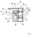
- the connecting piece 1 is intended to be part of an assembly of two sections, namely a profile 2 forming a cross member and a section 3 forming amount.
- This assembly of profiles 2, 3 belongs to a frame of door or French window of which it is part of the frame.
- This frame includes of course another section forming amount and another profile forming a cross.
- the profile 2 forming a cross member is a threshold profile and it bears against the face F of the floor S of the construction for which the door or the French window is intended.
- the section 2 forming a cross member is disposed horizontally, and towards the bottom of the frame, its extrados 4 being directed downwards and located against the face F, while its intrados 5 is directed upwards. and arranged to receive the other components of the door or the French window.
- the profile 3 forming upright is arranged vertically, and on one side of the frame - it being understood that there are two profiles in all, one on each side - its extrados 6 being directed towards the exterior of the chassis and its intrados 7 directed towards the inside of the chassis and arranged to receive the other constituent elements of the door or the French window.
- the profile 2 forming a cross member extends along a first horizontal direction 8 and the profile 3 forming a pillar extends along a second direction 9, vertical.
- the profile 2 forming a cross member has an end end portion 10 and a free end transverse face 11.
- the profiled section 3 comprises an end end portion 12 and a free end transverse face 13.
- the two sections 2, 3 are arranged to form an angle extending along a third direction 14, perpendicular to the two directions 8, 9, this third direction being disposed horizontally, perpendicular to the main plane 15 of the frame, arranged vertically and frontally.
- the extrados 4 and the free end transverse face 13 are substantially coplanar.
- the connecting piece 1 is interposed between the two sections 2, 3 as described.
- the section 2 forming a cross has a intrados 5 tormented form adapted to the needs. It comprises in particular, on one of its longitudinal edges, a wing flange 16 parallel to the main plane 15 and, on the other of its longitudinal edges, a wing return 17 located at least substantially in a horizontal plane. It also includes a median depression 18.
- the profile 3 forming upright has, in cross section, a general shape of U or pseudo U. It comprises in particular, on its longitudinal edges, a rim flange 19 and a rim flange 20, parallel to each other and to the main plane 15, and facing each other. It also comprises a core 21 perpendicular to the main plane 15. The edge flanges 19 and 20 and the core 21 define an internal cavity 22.
- the profile 3 also comprises a profiled projection 23 having in cross section a general staircase shape.
- the connecting piece 1, monobloc, has a first 24 and a second 25 parts.
- the first portion 24 extends in the first direction 8 and the second portion 25 in the second direction 9.
- the first part 24 has an extrados 26, limited by a plane, and coming against the face F of the construction.
- the first portion 24 has a lower surface 27 spaced from the extrados 26. On a first side 28, the first portion 24 has a free end transverse face 29 connecting the extrados 26 and the intrados 27.
- the first part 24 is placed at the end and in the extension of the profile 2 forming a cross member, so that the respective free end transverse faces 29, 11 come against each other.
- the first part 24 has a intrados 27 of tormented shape adapted to the intrados 5 of the profile 2 forming a cross. It comprises in particular, on one of its longitudinal edges, a face 30, intended to be coplanar with the edge wing 16 and the edge wing 19, and on the other of its longitudinal edges, a face 31, projecting, intended to be coplanar wing return 17.
- This face 31 comprises, towards the central zone, a face 32 parallel to the main plane 15.
- the second part 25 has a general flat tab shape adjoining the second side 33 of the first part 24. Its upper surface 34 is limited by a plane and it forms with the extrados 26 of the first part 24, an angle 35, s' extending in the third direction 14.
- two tabs 36a and 36b are provided, separated from each other by a space 37.
- the tab 36a is adjacent to the face 30 while extending towards the median zone, while the tab 36b is adjacent to the face 31 that it extends at an angle upwards.
- the second part 25 is placed against the intrados 7 of the end portion 12 of the section 3 forming amount.
- a first pair of through-holes 38 are provided in the first portion 24.
- a second pair of through-holes 39 are provided in the second portion 25.
- the pairs of holes 38, 39 extend along the first direction 8 and open into the extrados 34 of the second part 25.
- the first pair of through holes 38 opens on the other hand into the free end transverse face 29 of the first portion 24.
- the second pair of through holes 39 opens on the other hand, as for it, in the lower surface 40 of the second part 25.
- a first pair of screws 41 passes through the first pair of holes 38 and ensures the reciprocal attachment of the profile 2 forming a cross member to the first portion 24 of the connecting piece 1, these screws 41 coming to bear on the upper surface 34 of the second part 25.
- a second pair of screws 42 passes through the second pair of holes 39 and ensures the reciprocal attachment of the section 3 forming the upright to the second part 25 of the connecting piece, these screws 42 coming to rest on the underside 40 of the second part 25.
- the connecting piece 1 comprises means enabling the establishment of a bonding material (bonding) and reported sealing, ensuring the bonding (bonding) and sealing towards the end portion 12 of the profile 3 forming amount and between the profiles 2, 3 and the face F of the construction.
- These means comprise firstly a hole 43 for injection of the material for joining (bonding) and sealing located on the intrados 27 of the first part 24 and more particularly on the face 31, in the vicinity of the face 32.
- These means then comprise a channel 44 for passage of the material for joining (gluing) and sealing, formed in the first part 24 between the upper surface 26 and the lower surface 27. This channel extends along the second direction 9 .
- the channel 44 communicates on one side with the injection hole 43. It opens on the other side into a notch 45.
- These means also comprise the notch 45 formed in the extrados 26 of the first portion 24 and extending along the first direction 8 towards the second portion 25 and to its upper surface 34.
- the notch 45 does not open into the upper surface 34.
- the injection hole 43 is located in the profiled internal cavity 22 of the section 3 forming the upright.
- the notch 45 is located towards the face F of the construction.
- the notch 45 has a cross section at least substantially quarter-circle in concavity facing downwards and the middle zone.
- a projection 46 is provided, on the upper surface 34 of the second part 25, a projection 46, around the notch 45.
- the projection 46 is substantially in the shape of a quarter circle.
- the projection 46 has the function of coming against a protrusion 48 of the profile 3 forming an upright, in order to confine the space filled with material for joining (gluing) and sealing with the notch 45 up to the face F of the construction and up to the section 3 forming amount.
- a profiled groove 47 is provided in the connecting piece 1, at least substantially median. This groove 47 is disposed transversely to the third direction 14, that is to say parallel to the main plane 15.
- This groove 47 extends from the extrados 34 of the second portion 25 to the first side 28 of the first portion 24, between its extrados 26 and its intrados 27.
- the groove 47 forms a housing in which the projection can cooperate with adjustment. profiled 23 of the profile 3 forming amount.
- the injection hole 43, the passage channel 44 and the notch 45 are located in the vicinity and on the same side of the groove 47, one face of which is the face 32. It is on this side that is injected the bonding material (bonding) and sealing.
- the profile 3 forming the upright is placed on the construction.
- the connecting piece 1 is fixed to the profile 2 forming a cross member by means of the first pair of screws 41, coming against the extrados 34 of the second part 25.
- the profile 2 forming a cross member provided with its associated connecting piece 1, is positioned against the face F of the construction, the extrados 34 of the second portion 25 coming against the intrados of the profile 3 forming an upright in its end end portion 12.
- the reciprocating attachment of the connecting piece 1 to the profile 3 forming the upright is carried out by means of the second pair of screws 41, put in place by the inside of the assembly and coming against the lower surface 40 of the second part 25.
- the bonding material (bonding) and sealant is injected into the injection hole 43, until bonding (bonding) and sealing towards the end portion 12 of the profile 3 forming the upright, a part between the connecting piece 1 - more precisely its notch 45 - and the intrados 7 of the profile 3 forming upright and the projection 23 which is provided with this profile, on the other hand between the connecting piece 1 - more precisely its notch 45 - and the face F of the construction.
- the profile 2 forming a cross member is a threshold profile.
Landscapes
- Engineering & Computer Science (AREA)
- Civil Engineering (AREA)
- Structural Engineering (AREA)
- Joining Of Corner Units Of Frames Or Wings (AREA)
- Joining Of Building Structures In Genera (AREA)
Applications Claiming Priority (1)
| Application Number | Priority Date | Filing Date | Title |
|---|---|---|---|
| FR0707717A FR2923258B1 (fr) | 2007-11-02 | 2007-11-02 | Piece de liaison et assemblage de profiles comportant une telle piece |
Publications (2)
| Publication Number | Publication Date |
|---|---|
| EP2055885A2 true EP2055885A2 (de) | 2009-05-06 |
| EP2055885A3 EP2055885A3 (de) | 2012-01-04 |
Family
ID=39642893
Family Applications (1)
| Application Number | Title | Priority Date | Filing Date |
|---|---|---|---|
| EP08352025A Withdrawn EP2055885A3 (de) | 2007-11-02 | 2008-10-31 | Verbindungsstück und Verbindung von Profilen mit diesem Stück |
Country Status (2)
| Country | Link |
|---|---|
| EP (1) | EP2055885A3 (de) |
| FR (1) | FR2923258B1 (de) |
Cited By (5)
| Publication number | Priority date | Publication date | Assignee | Title |
|---|---|---|---|---|
| EP2199523A1 (de) | 2008-12-22 | 2010-06-23 | Hermann Gutmann Werke AG | Verbinder |
| CN110863762A (zh) * | 2019-10-25 | 2020-03-06 | 广东贝克洛幕墙门窗系统有限公司 | 一种角部注胶密封件及注胶方法 |
| WO2024086275A1 (en) * | 2022-10-19 | 2024-04-25 | Allegion Access Technologies LLC | Connection system for a header and a jamb of a door assembly |
| WO2024260471A1 (zh) * | 2023-06-19 | 2024-12-26 | 禾邑精智(上海)科技有限公司 | 组合型材、隐形收口结构及其施工方法 |
| US12291919B1 (en) * | 2021-12-03 | 2025-05-06 | Andersen Corporation | Inject clip for fenestration frames and methods |
Families Citing this family (1)
| Publication number | Priority date | Publication date | Assignee | Title |
|---|---|---|---|---|
| CN106761256A (zh) * | 2017-04-01 | 2017-05-31 | 孙伟 | 一种铝型材连接码 |
Citations (1)
| Publication number | Priority date | Publication date | Assignee | Title |
|---|---|---|---|---|
| FR2759111A1 (fr) | 1997-02-06 | 1998-08-07 | Alcan France | Dispositif pour l'assemblage de profiles d'un chassis de porte, fenetre ou analogue |
Family Cites Families (1)
| Publication number | Priority date | Publication date | Assignee | Title |
|---|---|---|---|---|
| DE19938218A1 (de) * | 1999-08-12 | 2001-02-15 | Hans Dieter Niemann | T-Verbindung von Hohlprofilstäben und Verfahren zum Herstellen einer T-Verbindung |
-
2007
- 2007-11-02 FR FR0707717A patent/FR2923258B1/fr not_active Expired - Fee Related
-
2008
- 2008-10-31 EP EP08352025A patent/EP2055885A3/de not_active Withdrawn
Patent Citations (1)
| Publication number | Priority date | Publication date | Assignee | Title |
|---|---|---|---|---|
| FR2759111A1 (fr) | 1997-02-06 | 1998-08-07 | Alcan France | Dispositif pour l'assemblage de profiles d'un chassis de porte, fenetre ou analogue |
Cited By (6)
| Publication number | Priority date | Publication date | Assignee | Title |
|---|---|---|---|---|
| EP2199523A1 (de) | 2008-12-22 | 2010-06-23 | Hermann Gutmann Werke AG | Verbinder |
| CN110863762A (zh) * | 2019-10-25 | 2020-03-06 | 广东贝克洛幕墙门窗系统有限公司 | 一种角部注胶密封件及注胶方法 |
| US12291919B1 (en) * | 2021-12-03 | 2025-05-06 | Andersen Corporation | Inject clip for fenestration frames and methods |
| WO2024086275A1 (en) * | 2022-10-19 | 2024-04-25 | Allegion Access Technologies LLC | Connection system for a header and a jamb of a door assembly |
| US12241307B2 (en) | 2022-10-19 | 2025-03-04 | Allegion Access Technologies LLC | Connection system for a header and a jamb of a door assembly |
| WO2024260471A1 (zh) * | 2023-06-19 | 2024-12-26 | 禾邑精智(上海)科技有限公司 | 组合型材、隐形收口结构及其施工方法 |
Also Published As
| Publication number | Publication date |
|---|---|
| FR2923258A1 (fr) | 2009-05-08 |
| FR2923258B1 (fr) | 2009-12-18 |
| EP2055885A3 (de) | 2012-01-04 |
Similar Documents
| Publication | Publication Date | Title |
|---|---|---|
| EP0778168B1 (de) | An einer Fahrzeugöffnung anliegende Schliessvorrichtung | |
| EP3740388A1 (de) | Vorrichtung zum führen eines schiebefensters, mit dieser vorrichtung ausgestattete verglaste fahrzeugtür und mit einer solchen tür ausgestattetes fahrzeug | |
| FR2923258A1 (fr) | Piece de liaison et assemblage de profiles comportant une telle piece | |
| FR2983895A1 (fr) | Barriere a profiles rigides et profiles d'habillage | |
| FR2600694A1 (fr) | Raccordement entre une traverse et un poteau dans une construction metallique | |
| FR3075854A1 (fr) | Chassis forme de profiles | |
| FR2800437A1 (fr) | Ensemble constitue d'un support rigide et d'un habillage du support, profile d'habillage et son utilisation pour un tel ensemble | |
| EP2053189B1 (de) | Rahmen mit Fenster- oder Türflügel | |
| EP2253793B1 (de) | Verbindung resultierend aus einem Verbund mit geradem Schnitt | |
| FR2924450A1 (fr) | Poteau composite pour la formation de cloison et cloison comportant un tel poteau | |
| FR2839697A1 (fr) | Systeme de montage d'un ouvrant sur une structure de vehicule automobile | |
| FR2851005A1 (fr) | Volet roulant | |
| FR2570748A1 (fr) | Dispositif d'assemblage simplifie des differentes parties de fenetres, portes et ouvertures similaires, en bois, ainsi que tout agencement de meubles | |
| FR2954391A1 (fr) | Ensemble chambranle contre-chambranle | |
| EP1120302A1 (de) | Rahmenanordnung für Glas oder Fenster, fest oder mobil | |
| FR2967443A1 (fr) | Huisserie pour porte ou fenetre composee de deux plaques de platre | |
| FR2770253A1 (fr) | Dispositif de drainage des eaux d'infiltration pour chassis fixe, notamment pour chassis d'ouvrant de porte ou fenetre | |
| EP1767438A1 (de) | A-Säule für eine Kraftfahrzeugkarosserie | |
| EP2491837A1 (de) | Duschkabine aus Steckverbindungspaneelen | |
| FR2981378A1 (fr) | Dispositif pour la realisation d'un bassin de piscine | |
| FR2539336A1 (fr) | Cabine de peinture en panneaux modulaires | |
| FR2642789A1 (fr) | Coffrage de volet roulant pour installation sur la partie superieure d'un cadre de dormant | |
| FR2705380A1 (fr) | Profile cintré à rainures latérales pour structure de couverture découvrable. | |
| FR2776048A1 (fr) | Profile pour menuiserie du type coulissante | |
| FR2880909A1 (fr) | Joue pour coffre de volet et coffre comprenant au moins deux joues |
Legal Events
| Date | Code | Title | Description |
|---|---|---|---|
| PUAI | Public reference made under article 153(3) epc to a published international application that has entered the european phase |
Free format text: ORIGINAL CODE: 0009012 |
|
| AK | Designated contracting states |
Kind code of ref document: A2 Designated state(s): AT BE BG CH CY CZ DE DK EE ES FI FR GB GR HR HU IE IS IT LI LT LU LV MC MT NL NO PL PT RO SE SI SK TR |
|
| AX | Request for extension of the european patent |
Extension state: AL BA MK RS |
|
| PUAL | Search report despatched |
Free format text: ORIGINAL CODE: 0009013 |
|
| AK | Designated contracting states |
Kind code of ref document: A3 Designated state(s): AT BE BG CH CY CZ DE DK EE ES FI FR GB GR HR HU IE IS IT LI LT LU LV MC MT NL NO PL PT RO SE SI SK TR |
|
| AX | Request for extension of the european patent |
Extension state: AL BA MK RS |
|
| RIC1 | Information provided on ipc code assigned before grant |
Ipc: E06B 3/968 20060101ALI20111129BHEP Ipc: E06B 3/964 20060101ALI20111129BHEP Ipc: E06B 3/96 20060101AFI20111129BHEP |
|
| AKY | No designation fees paid | ||
| REG | Reference to a national code |
Ref country code: DE Ref legal event code: R108 |
|
| REG | Reference to a national code |
Ref country code: DE Ref legal event code: R108 Effective date: 20120912 |
|
| STAA | Information on the status of an ep patent application or granted ep patent |
Free format text: STATUS: THE APPLICATION IS DEEMED TO BE WITHDRAWN |
|
| 18D | Application deemed to be withdrawn |
Effective date: 20120705 |