EP2055898A2 - Aube de turbine dotée de refroidissement de plate-forme - Google Patents
Aube de turbine dotée de refroidissement de plate-forme Download PDFInfo
- Publication number
- EP2055898A2 EP2055898A2 EP08252910A EP08252910A EP2055898A2 EP 2055898 A2 EP2055898 A2 EP 2055898A2 EP 08252910 A EP08252910 A EP 08252910A EP 08252910 A EP08252910 A EP 08252910A EP 2055898 A2 EP2055898 A2 EP 2055898A2
- Authority
- EP
- European Patent Office
- Prior art keywords
- seal
- platforms
- gas turbine
- platform
- turbine engine
- Prior art date
- Legal status (The legal status is an assumption and is not a legal conclusion. Google has not performed a legal analysis and makes no representation as to the accuracy of the status listed.)
- Granted
Links
Images


Classifications
-
- F—MECHANICAL ENGINEERING; LIGHTING; HEATING; WEAPONS; BLASTING
- F01—MACHINES OR ENGINES IN GENERAL; ENGINE PLANTS IN GENERAL; STEAM ENGINES
- F01D—NON-POSITIVE DISPLACEMENT MACHINES OR ENGINES, e.g. STEAM TURBINES
- F01D11/00—Preventing or minimising internal leakage of working-fluid, e.g. between stages
- F01D11/005—Sealing means between non relatively rotating elements
- F01D11/006—Sealing the gap between rotor blades or blades and rotor
- F01D11/008—Sealing the gap between rotor blades or blades and rotor by spacer elements between the blades, e.g. independent interblade platforms
-
- F—MECHANICAL ENGINEERING; LIGHTING; HEATING; WEAPONS; BLASTING
- F01—MACHINES OR ENGINES IN GENERAL; ENGINE PLANTS IN GENERAL; STEAM ENGINES
- F01D—NON-POSITIVE DISPLACEMENT MACHINES OR ENGINES, e.g. STEAM TURBINES
- F01D5/00—Blades; Blade-carrying members; Heating, heat-insulating, cooling or antivibration means on the blades or the members
- F01D5/02—Blade-carrying members, e.g. rotors
- F01D5/08—Heating, heat-insulating or cooling means
- F01D5/081—Cooling fluid being directed on the side of the rotor disc or at the roots of the blades
-
- F—MECHANICAL ENGINEERING; LIGHTING; HEATING; WEAPONS; BLASTING
- F01—MACHINES OR ENGINES IN GENERAL; ENGINE PLANTS IN GENERAL; STEAM ENGINES
- F01D—NON-POSITIVE DISPLACEMENT MACHINES OR ENGINES, e.g. STEAM TURBINES
- F01D5/00—Blades; Blade-carrying members; Heating, heat-insulating, cooling or antivibration means on the blades or the members
- F01D5/12—Blades
- F01D5/14—Form or construction
- F01D5/18—Hollow blades, i.e. blades with cooling or heating channels or cavities; Heating, heat-insulating or cooling means on blades
- F01D5/187—Convection cooling
-
- F—MECHANICAL ENGINEERING; LIGHTING; HEATING; WEAPONS; BLASTING
- F05—INDEXING SCHEMES RELATING TO ENGINES OR PUMPS IN VARIOUS SUBCLASSES OF CLASSES F01-F04
- F05D—INDEXING SCHEME FOR ASPECTS RELATING TO NON-POSITIVE-DISPLACEMENT MACHINES OR ENGINES, GAS-TURBINES OR JET-PROPULSION PLANTS
- F05D2240/00—Components
- F05D2240/55—Seals
- F05D2240/57—Leaf seals
-
- F—MECHANICAL ENGINEERING; LIGHTING; HEATING; WEAPONS; BLASTING
- F05—INDEXING SCHEMES RELATING TO ENGINES OR PUMPS IN VARIOUS SUBCLASSES OF CLASSES F01-F04
- F05D—INDEXING SCHEME FOR ASPECTS RELATING TO NON-POSITIVE-DISPLACEMENT MACHINES OR ENGINES, GAS-TURBINES OR JET-PROPULSION PLANTS
- F05D2240/00—Components
- F05D2240/80—Platforms for stationary or moving blades
- F05D2240/81—Cooled platforms
-
- Y—GENERAL TAGGING OF NEW TECHNOLOGICAL DEVELOPMENTS; GENERAL TAGGING OF CROSS-SECTIONAL TECHNOLOGIES SPANNING OVER SEVERAL SECTIONS OF THE IPC; TECHNICAL SUBJECTS COVERED BY FORMER USPC CROSS-REFERENCE ART COLLECTIONS [XRACs] AND DIGESTS
- Y02—TECHNOLOGIES OR APPLICATIONS FOR MITIGATION OR ADAPTATION AGAINST CLIMATE CHANGE
- Y02T—CLIMATE CHANGE MITIGATION TECHNOLOGIES RELATED TO TRANSPORTATION
- Y02T50/00—Aeronautics or air transport
- Y02T50/60—Efficient propulsion technologies, e.g. for aircraft
Definitions
- This invention relates generally to aircraft gas turbine engines and particularly to the cooling of the platform sections of turbine airfoils employed in such engines.
- gas turbine engines include a serial arrangement of a fan, a compressor, a combustor and a turbine. Air admitted into the inlet of the engine is compressed by the engine's compressor. The compressed air is then mixed with fuel in the engine's combustor and burned. The high-energy products of combustion of the burned air-fuel mixture then enter the turbine which extracts energy from the mixture in order to drive the compressor and fan. That energy extracted by the turbine above and beyond that which is necessary to drive the compressor and fan exits the engine at the core engine exhaust nozzle thereof producing thrust which powers an associated aircraft or operates a free turbine which drives an electrical generator, pump or the like.
- cooling turbine blades in this manner has been effective at minimizing oxidation, creep, and thermo-mechanical fatigue, particularly, in the airfoil sections of such blades, due in large measure to the airfoil's ability to accommodate complex networks of intricate patterns of cooling passages.
- While turbine blade configurations may lend themselves to cooling airfoils in such manner, such is not necessarily the case with the blade platforms.
- Such platforms tend to take the shape of longitudinally and circumferentially extensive thin plates which are not conducive to the provision therein of internal cooling passages.
- modem blade platforms employ no internal cooling passages at all, except perhaps for a series of cooling holes extending through the platform between the radially inner and outer major surfaces thereof.
- it has been the practice to bathe the underside of the platform with compressor bleed cooling air and channeling the cooling air through the cooling holes to the radially outer surface of the platform where the air mixes with the engine's working fluid.
- the air which bathes the underside of the platform is, for the most part, stagnant, the flow of cooling air through the holes resulting from the difference in pressure between the cooling air and the combustion. While bathing the underside of the blade platform in stagnant compressor blade cooling air does provide some cooling, it has been observed that often, such cooling hindered by the presence of platform-to-platform seals which bear against the underside of the platform and may be insufficient to prevent oxidation, creep, and thermo-mechanical fatigue of the platform. The portion of the blade platform near the cooling holes has been particularly susceptible to thermo-mechanical fatigue which manifests itself in cracking in the high stress around the cooling holes.
- enhanced cooling of a turbine blade platform can be achieved by accelerating the essentially stagnant reservoir of air interiorly of the platform to a speed which enhances the convective cooling afforded by such air.
- the turbine blade platforms are more effectively cooled and thermo-mechanical fatigue experienced by the platforms is greatly reduced.
- the cooling air acceleration is provided by grooves formed between a platform-to-platform seal and the platform's radially inner surface.
- the grooves provide direct exposure of the radially inner platform surface to the cooling air and reduces the flow area of the cooling air adjacent the radially inner platform surface whereby the pressure difference between the cooling air adjacent the inner surface of the seal and the working fluid flowing past the outer surface of the seal, accelerates the cooling air to the aforementioned higher velocities.
- the grooves may be provided in the radially outer surface of the seal, the radially inner surface of the platform, or in both those members.
- the grooves extend in the general direction of rotation of the engine's rotor for ease in manufacturing and to enhance the acceleration of the cooling air by establishing a circumferential pumping of the cooling air through the grooves.
- a feather seal for sealing a gap between respective platforms of adjacent gas turbine engine components as claimed in claim 12.
- a circular array of turbine airfoils in a gas turbine engine each of said turbine airfoils including an airfoil portion and a platform defining across a first major surface thereof, a boundary for the flow of working fluid past said airfoil portion, each of said platforms including an opposite, second major surface communicating with a reservoir of cooling air at a pressure higher than that of said working fluid, said gas turbine engine including flow accelerators spanning said platforms of adjacent turbine airfoil blades, said flow accelerators reducing the volume of said cooling air applied to said second major surface of said platform to accelerate the flow thereof, thereby enhancing the convection cooling of said platform by said cooling air.
- said flow accelerators comprise seals which span adjacent blade platforms along said second major surfaces thereof, at least one of said seals and said second major surfaces of said blade platforms defining passages fed by said reservoir of cooling air.
- said adjacent blade platforms are spaced apart by a gap, said seals spanning said gap and said passages discharging said cooling air into said working fluid at outlets of said passages in fluid communication with said gap.
- said passages comprise open grooves formed in the second major surfaces of said platforms, said grooves being at least partially closed by surface-to-surface contact between said grooves and a major surface of said seal.
- said passages comprise grooves formed in major surfaces of said seals, said grooves being at least partially closed by surface-to-surface contact between said grooves and said second major surfaces of said platforms.
- said grooves are formed in a radially outer surface of said seal and said second major surface of said platform comprises a radially inner major surface thereof.
- said grooves in said radially outer major surface of said seal are open along those portions thereof between said adjacent turbine airfoil blade platforms in said gap.
- the present invention is utilized on a single stage turbine typically a high-pressure turbine of a modem gas turbine engine.
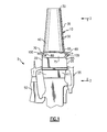
- the turbine rotor generally illustrated by reference number 5 is comprised of a plurality of circumferentially spaced turbine blades 10 suitably mounted in broach slots 15 formed in the rim 20 of a turbine disk 25.
- the mounting of the blades to the disk is by the well-known broached-fir tree attachment at the blade's root portion 27.
- the blades are internally air cooled from compressor discharge air that is fed to the blade from the space between the blade and the rim of the disk by any well-known distribution system (not shown).
- a plurality of radially spaced apertures 30 extending adjacent to the trailing edge 35 of airfoil portion 40 of blade 10 discharges the cooling air from cooling passages internally of the blade (not shown) into the engine's working fluid (combustor discharge gases).
- the blades 10 are held in axial position by plates 50 and 55 mounted on the fore and aft faces of the disk 25.
- Each of the blades includes a platform 60 which defines the radially inner surface of the working fluid flow path disposed between the airfoil portion 40 of the blade 10 and the root portion 27.
- the platform 60 extends longitudinally and circumferentially from the airfoil and abut side to side with adjacent blade platforms around the circumference of the disk.
- the platforms are defined in part by radially inner and outer major surfaces 65 and 70 with cooling holes 73 extending therethrough (see Fig. 3 ).
- Inner surface 65 defines the outer surface of a pocket or plenum 75 which accommodates cooling air provided by the aforementioned distribution system.
- the platforms also include fore and aft hooks 80 and 85 which define the fore and aft extremities of plenum 75.
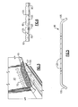
- feather seal 95 is comprised of an elongate, generally flat, sheet metal plate having radially inwardly curved end portions 100 and 105 which loosely seat against the fore and aft ends of plenums 75 outwardly of hooks 80 and 85.
- the seals are typically manufactured from material such as a cobalt alloy which can withstand the heat loading from the engine's working fluid which contacts the seal through gap 90. Hooks 80 and 85 radially retain the seal within plenum 75 during static conditions, the seal being held against radially inner platform surface 65 by centrifugal force during operation of the engine.
- the seal is generally parallelogram shaped. Portions of the longitudinal (side) edges thereof, may be concave (110) and convex (115) to accommodate suction and pressure surfaces of those portions of adjacent blade airfoil portions 40 which extend radially interiorly of the platform.
- the seal may also be notched as at 120 to accommodate or provide a mounting location for any suitable blade vibration damper (not shown).
- the feather seal is also grooved along spaced locations 125, the grooves extending generally parallel to ends 100 and 105, in the direction of rotation of the engine's rotor. Alternately, the grooves may extend partway across the seal in a staggered arrangement as shown in Fig. 7 or any other suitable pattern such as the serpentine or crosshatch patterns shown in Fig. 8 .
- seal 95 is grooved along its radially outer surface, and since the width of the seal is less extensive than that of the platform, compressor discharge cooling air fills grooves 125 in the seal from plenum 75, around the longitudinal edges of the seal.
- each individual groove in feather seal 95 experiences the pressure difference between the cooling air at the radially inner surface of the platform and the combustion gases at the radially outer surface thereof.
- a flow of cooling air is established in each groove which in turn establishes effective convection cooling of the radially inner surfaces of the blade platforms which overlie the grooves. Cooling the platforms in this manner has, in laboratory tests, resulted in platform temperature reductions at the outer surface thereof on the order of five percent and reduced cracking in the platform areas near the cooling holes.
Landscapes
- Engineering & Computer Science (AREA)
- Mechanical Engineering (AREA)
- General Engineering & Computer Science (AREA)
- Turbine Rotor Nozzle Sealing (AREA)
Applications Claiming Priority (1)
| Application Number | Priority Date | Filing Date | Title |
|---|---|---|---|
| US11/982,578 US8240981B2 (en) | 2007-11-02 | 2007-11-02 | Turbine airfoil with platform cooling |
Publications (3)
| Publication Number | Publication Date |
|---|---|
| EP2055898A2 true EP2055898A2 (fr) | 2009-05-06 |
| EP2055898A3 EP2055898A3 (fr) | 2012-10-31 |
| EP2055898B1 EP2055898B1 (fr) | 2019-01-09 |
Family
ID=40303578
Family Applications (1)
| Application Number | Title | Priority Date | Filing Date |
|---|---|---|---|
| EP08252910.8A Active EP2055898B1 (fr) | 2007-11-02 | 2008-09-02 | Moteur de turbine à gaz avec aubes arrangées circonférentiellement et dotées de refroidissement de plate-forme |
Country Status (2)
| Country | Link |
|---|---|
| US (1) | US8240981B2 (fr) |
| EP (1) | EP2055898B1 (fr) |
Cited By (5)
| Publication number | Priority date | Publication date | Assignee | Title |
|---|---|---|---|---|
| CN102444431A (zh) * | 2010-09-30 | 2012-05-09 | 通用电气公司 | 用于冷却涡轮转子叶片平台区的装置与方法 |
| EP2360350A3 (fr) * | 2010-02-24 | 2014-08-20 | United Technologies Corporation | Rainure d'une bande d'étanchéité combinée avec un évidement |
| EP3170989A1 (fr) * | 2015-11-19 | 2017-05-24 | United Technologies Corporation | Agencement de joint rainuré pour moteur à turbine |
| EP3447248A1 (fr) * | 2017-08-21 | 2019-02-27 | Siemens Aktiengesellschaft | Ensemble pale de turbine comprenant un é?lé?ment d'étanché?ité? constitué? d'un maté?riau adhé?sif |
| US10851661B2 (en) | 2017-08-01 | 2020-12-01 | General Electric Company | Sealing system for a rotary machine and method of assembling same |
Families Citing this family (25)
| Publication number | Priority date | Publication date | Assignee | Title |
|---|---|---|---|---|
| US8393869B2 (en) | 2008-12-19 | 2013-03-12 | Solar Turbines Inc. | Turbine blade assembly including a damper |
| US8814517B2 (en) * | 2010-09-30 | 2014-08-26 | General Electric Company | Apparatus and methods for cooling platform regions of turbine rotor blades |
| US9022727B2 (en) * | 2010-11-15 | 2015-05-05 | Mtu Aero Engines Gmbh | Rotor for a turbo machine |
| US8727710B2 (en) | 2011-01-24 | 2014-05-20 | United Technologies Corporation | Mateface cooling feather seal assembly |
| EP2520764A1 (fr) * | 2011-05-02 | 2012-11-07 | MTU Aero Engines GmbH | Aube avec pied refroidi |
| US8376705B1 (en) * | 2011-09-09 | 2013-02-19 | Siemens Energy, Inc. | Turbine endwall with grooved recess cavity |
| US9022735B2 (en) | 2011-11-08 | 2015-05-05 | General Electric Company | Turbomachine component and method of connecting cooling circuits of a turbomachine component |
| EP2679770A1 (fr) * | 2012-06-26 | 2014-01-01 | Siemens Aktiengesellschaft | Bande d'étanchéité pour plate-forme de turbine à gaz |
| US9021816B2 (en) | 2012-07-02 | 2015-05-05 | United Technologies Corporation | Gas turbine engine turbine vane platform core |
| US10364680B2 (en) * | 2012-08-14 | 2019-07-30 | United Technologies Corporation | Gas turbine engine component having platform trench |
| US9546554B2 (en) | 2012-09-27 | 2017-01-17 | Honeywell International Inc. | Gas turbine engine components with blade tip cooling |
| US9303519B2 (en) | 2012-10-31 | 2016-04-05 | Solar Turbines Incorporated | Damper for a turbine rotor assembly |
| US9297263B2 (en) | 2012-10-31 | 2016-03-29 | Solar Turbines Incorporated | Turbine blade for a gas turbine engine |
| US9347325B2 (en) | 2012-10-31 | 2016-05-24 | Solar Turbines Incorporated | Damper for a turbine rotor assembly |
| US9228443B2 (en) | 2012-10-31 | 2016-01-05 | Solar Turbines Incorporated | Turbine rotor assembly |
| WO2014160641A1 (fr) * | 2013-03-25 | 2014-10-02 | United Technologies Corporation | Pale de rotor à languette d'étanchéité en forme de l |
| US9581036B2 (en) * | 2013-05-14 | 2017-02-28 | General Electric Company | Seal system including angular features for rotary machine components |
| WO2015026416A2 (fr) * | 2013-06-03 | 2015-02-26 | United Technologies Corporation | Amortisseurs de vibrations pour pales de turbine |
| US9713843B2 (en) | 2014-01-22 | 2017-07-25 | United Technologies Corporation | Method for additively constructing internal channels |
| US10030530B2 (en) * | 2014-07-31 | 2018-07-24 | United Technologies Corporation | Reversible blade rotor seal |
| US10458264B2 (en) | 2015-05-05 | 2019-10-29 | United Technologies Corporation | Seal arrangement for turbine engine component |
| US10641111B2 (en) * | 2018-08-31 | 2020-05-05 | Rolls-Royce Corporation | Turbine blade assembly with ceramic matrix composite components |
| US11156116B2 (en) * | 2019-04-08 | 2021-10-26 | Honeywell International Inc. | Turbine nozzle with reduced leakage feather seals |
| CN113356930B (zh) * | 2021-05-31 | 2022-05-20 | 北京南方斯奈克玛涡轮技术有限公司 | 一种带有加强冷却结构的涡轮转子装置 |
| US11506060B1 (en) * | 2021-07-15 | 2022-11-22 | Honeywell International Inc. | Radial turbine rotor for gas turbine engine |
Family Cites Families (22)
| Publication number | Priority date | Publication date | Assignee | Title |
|---|---|---|---|---|
| US3728041A (en) * | 1971-10-04 | 1973-04-17 | Gen Electric | Fluidic seal for segmented nozzle diaphragm |
| US3752598A (en) * | 1971-11-17 | 1973-08-14 | United Aircraft Corp | Segmented duct seal |
| US4431373A (en) * | 1980-05-16 | 1984-02-14 | United Technologies Corporation | Flow directing assembly for a gas turbine engine |
| US4465284A (en) * | 1983-09-19 | 1984-08-14 | General Electric Company | Scalloped cooling of gas turbine transition piece frame |
| US4557412A (en) * | 1983-12-05 | 1985-12-10 | United Technologies Corporation | Intersecting feather seals and construction thereof |
| US4767260A (en) * | 1986-11-07 | 1988-08-30 | United Technologies Corporation | Stator vane platform cooling means |
| US4813848A (en) * | 1987-10-14 | 1989-03-21 | United Technologies Corporation | Turbine rotor disk and blade assembly |
| US4872810A (en) * | 1988-12-14 | 1989-10-10 | United Technologies Corporation | Turbine rotor retention system |
| JPH03213602A (ja) * | 1990-01-08 | 1991-09-19 | General Electric Co <Ge> | ガスタービンエンジンの当接セグメントを連結する自己冷却式ジョイント連結構造 |
| US5221096A (en) * | 1990-10-19 | 1993-06-22 | Allied-Signal Inc. | Stator and multiple piece seal |
| US5281097A (en) * | 1992-11-20 | 1994-01-25 | General Electric Company | Thermal control damper for turbine rotors |
| GB2280935A (en) * | 1993-06-12 | 1995-02-15 | Rolls Royce Plc | Cooled sealing strip for nozzle guide vane segments |
| US5374161A (en) * | 1993-12-13 | 1994-12-20 | United Technologies Corporation | Blade outer air seal cooling enhanced with inter-segment film slot |
| US5531457A (en) * | 1994-12-07 | 1996-07-02 | Pratt & Whitney Canada, Inc. | Gas turbine engine feather seal arrangement |
| US5513955A (en) * | 1994-12-14 | 1996-05-07 | United Technologies Corporation | Turbine engine rotor blade platform seal |
| FR2758855B1 (fr) * | 1997-01-30 | 1999-02-26 | Snecma | Systeme de ventilation des plates-formes des aubes mobiles |
| US6210111B1 (en) * | 1998-12-21 | 2001-04-03 | United Technologies Corporation | Turbine blade with platform cooling |
| US6315298B1 (en) * | 1999-11-22 | 2001-11-13 | United Technologies Corporation | Turbine disk and blade assembly seal |
| FR2810365B1 (fr) * | 2000-06-15 | 2002-10-11 | Snecma Moteurs | Systeme de ventilation d'une paire de plates-formes d'aubes juxtaposees |
| EP1286021B1 (fr) * | 2001-08-21 | 2010-10-27 | Alstom Technology Ltd | Procédé de fabrication d' un évidement ayant la forme d' une rainure et évidement ayant la forme d' une rainure correspondant |
| GB0304329D0 (en) * | 2003-02-26 | 2003-04-02 | Rolls Royce Plc | Damper seal |
| SE0502644L (sv) * | 2005-12-02 | 2007-06-03 | Siemens Ag | Kylning av plattformar till turbinskovlar i turbiner |
-
2007
- 2007-11-02 US US11/982,578 patent/US8240981B2/en active Active
-
2008
- 2008-09-02 EP EP08252910.8A patent/EP2055898B1/fr active Active
Cited By (8)
| Publication number | Priority date | Publication date | Assignee | Title |
|---|---|---|---|---|
| EP2360350A3 (fr) * | 2010-02-24 | 2014-08-20 | United Technologies Corporation | Rainure d'une bande d'étanchéité combinée avec un évidement |
| CN102444431A (zh) * | 2010-09-30 | 2012-05-09 | 通用电气公司 | 用于冷却涡轮转子叶片平台区的装置与方法 |
| CN102444431B (zh) * | 2010-09-30 | 2015-11-25 | 通用电气公司 | 用于冷却涡轮转子叶片平台区的装置与方法 |
| EP3170989A1 (fr) * | 2015-11-19 | 2017-05-24 | United Technologies Corporation | Agencement de joint rainuré pour moteur à turbine |
| US9822658B2 (en) | 2015-11-19 | 2017-11-21 | United Technologies Corporation | Grooved seal arrangement for turbine engine |
| US10001023B2 (en) | 2015-11-19 | 2018-06-19 | United Technologies Corporation | Grooved seal arrangement for turbine engine |
| US10851661B2 (en) | 2017-08-01 | 2020-12-01 | General Electric Company | Sealing system for a rotary machine and method of assembling same |
| EP3447248A1 (fr) * | 2017-08-21 | 2019-02-27 | Siemens Aktiengesellschaft | Ensemble pale de turbine comprenant un é?lé?ment d'étanché?ité? constitué? d'un maté?riau adhé?sif |
Also Published As
| Publication number | Publication date |
|---|---|
| US8240981B2 (en) | 2012-08-14 |
| EP2055898A3 (fr) | 2012-10-31 |
| EP2055898B1 (fr) | 2019-01-09 |
| US20090116953A1 (en) | 2009-05-07 |
Similar Documents
| Publication | Publication Date | Title |
|---|---|---|
| US8240981B2 (en) | Turbine airfoil with platform cooling | |
| US6607355B2 (en) | Turbine airfoil with enhanced heat transfer | |
| EP3088675B1 (fr) | Aube rotorique et turbine à gaz associée | |
| EP2610436B1 (fr) | Aube de rotor de turbine avec refroidissement de la plate-forme | |
| CN1987055B (zh) | 平衡冷却的涡轮机喷嘴 | |
| US8684664B2 (en) | Apparatus and methods for cooling platform regions of turbine rotor blades | |
| EP3088674B1 (fr) | Pale de rotor et turbine à gaz associée | |
| US8967973B2 (en) | Turbine bucket platform shaping for gas temperature control and related method | |
| US10156144B2 (en) | Turbine airfoil and method of cooling | |
| EP1424467A2 (fr) | Rangée de cordes longues et courtes d'aubes de turbine | |
| EP2586974B1 (fr) | Aube rotorique de turbine ayant un gondolage de bord d'attaque de plate-forme pour la performance et le flux secondaire, rotor de turbine et procédé de commande de flux secondaire de purge associés | |
| US8573925B2 (en) | Cooled component for a gas turbine engine | |
| EP2586995A2 (fr) | Éléments d'aile d'ange pour aube de turbine pour la commande d'écoulement de cavité avant et procédé associé | |
| US20200378262A1 (en) | Gas turbine engines with improved airfoil dust removal | |
| US10323523B2 (en) | Blade platform cooling in a gas turbine | |
| EP2623719B1 (fr) | Fentes de soulagement de contrainte pour bague d'aube de turbine | |
| KR102699389B1 (ko) | 터보 기계의 로터 블레이드 |
Legal Events
| Date | Code | Title | Description |
|---|---|---|---|
| PUAI | Public reference made under article 153(3) epc to a published international application that has entered the european phase |
Free format text: ORIGINAL CODE: 0009012 |
|
| AK | Designated contracting states |
Kind code of ref document: A2 Designated state(s): AT BE BG CH CY CZ DE DK EE ES FI FR GB GR HR HU IE IS IT LI LT LU LV MC MT NL NO PL PT RO SE SI SK TR |
|
| AX | Request for extension of the european patent |
Extension state: AL BA MK RS |
|
| PUAL | Search report despatched |
Free format text: ORIGINAL CODE: 0009013 |
|
| AK | Designated contracting states |
Kind code of ref document: A3 Designated state(s): AT BE BG CH CY CZ DE DK EE ES FI FR GB GR HR HU IE IS IT LI LT LU LV MC MT NL NO PL PT RO SE SI SK TR |
|
| AX | Request for extension of the european patent |
Extension state: AL BA MK RS |
|
| RIC1 | Information provided on ipc code assigned before grant |
Ipc: F01D 11/00 20060101AFI20120925BHEP Ipc: F01D 5/18 20060101ALI20120925BHEP Ipc: F01D 5/08 20060101ALI20120925BHEP |
|
| 17P | Request for examination filed |
Effective date: 20130430 |
|
| AKX | Designation fees paid |
Designated state(s): DE FR |
|
| RBV | Designated contracting states (corrected) |
Designated state(s): DE GB |
|
| RAP1 | Party data changed (applicant data changed or rights of an application transferred) |
Owner name: UNITED TECHNOLOGIES CORPORATION |
|
| STAA | Information on the status of an ep patent application or granted ep patent |
Free format text: STATUS: EXAMINATION IS IN PROGRESS |
|
| 17Q | First examination report despatched |
Effective date: 20161027 |
|
| GRAP | Despatch of communication of intention to grant a patent |
Free format text: ORIGINAL CODE: EPIDOSNIGR1 |
|
| STAA | Information on the status of an ep patent application or granted ep patent |
Free format text: STATUS: GRANT OF PATENT IS INTENDED |
|
| INTG | Intention to grant announced |
Effective date: 20180717 |
|
| GRAS | Grant fee paid |
Free format text: ORIGINAL CODE: EPIDOSNIGR3 |
|
| GRAA | (expected) grant |
Free format text: ORIGINAL CODE: 0009210 |
|
| STAA | Information on the status of an ep patent application or granted ep patent |
Free format text: STATUS: THE PATENT HAS BEEN GRANTED |
|
| AK | Designated contracting states |
Kind code of ref document: B1 Designated state(s): DE GB |
|
| REG | Reference to a national code |
Ref country code: GB Ref legal event code: FG4D |
|
| REG | Reference to a national code |
Ref country code: DE Ref legal event code: R096 Ref document number: 602008058669 Country of ref document: DE |
|
| REG | Reference to a national code |
Ref country code: DE Ref legal event code: R097 Ref document number: 602008058669 Country of ref document: DE |
|
| PLBE | No opposition filed within time limit |
Free format text: ORIGINAL CODE: 0009261 |
|
| STAA | Information on the status of an ep patent application or granted ep patent |
Free format text: STATUS: NO OPPOSITION FILED WITHIN TIME LIMIT |
|
| 26N | No opposition filed |
Effective date: 20191010 |
|
| REG | Reference to a national code |
Ref country code: DE Ref legal event code: R081 Ref document number: 602008058669 Country of ref document: DE Owner name: RAYTHEON TECHNOLOGIES CORPORATION (N.D.GES.D.S, US Free format text: FORMER OWNER: UNITED TECHNOLOGIES CORPORATION, FARMINGTON, CONN., US Ref country code: DE Ref legal event code: R081 Ref document number: 602008058669 Country of ref document: DE Owner name: RTX CORPORATION (N.D.GES.D. STAATES DELAWARE),, US Free format text: FORMER OWNER: UNITED TECHNOLOGIES CORPORATION, FARMINGTON, CONN., US |
|
| P01 | Opt-out of the competence of the unified patent court (upc) registered |
Effective date: 20230519 |
|
| PGFP | Annual fee paid to national office [announced via postgrant information from national office to epo] |
Ref country code: DE Payment date: 20250820 Year of fee payment: 18 |
|
| PGFP | Annual fee paid to national office [announced via postgrant information from national office to epo] |
Ref country code: GB Payment date: 20250822 Year of fee payment: 18 |
|
| REG | Reference to a national code |
Ref country code: DE Ref legal event code: R081 Ref document number: 602008058669 Country of ref document: DE Owner name: RTX CORPORATION (N.D.GES.D. STAATES DELAWARE),, US Free format text: FORMER OWNER: RAYTHEON TECHNOLOGIES CORPORATION (N.D.GES.D.STAATES DELAWARE), ARLINGTON, VA, US |