EP2055899B1 - Systèmes et procédés pour contrôler le jeu d'étanchéité dans un moteur de turbine - Google Patents
Systèmes et procédés pour contrôler le jeu d'étanchéité dans un moteur de turbine Download PDFInfo
- Publication number
- EP2055899B1 EP2055899B1 EP08253539.4A EP08253539A EP2055899B1 EP 2055899 B1 EP2055899 B1 EP 2055899B1 EP 08253539 A EP08253539 A EP 08253539A EP 2055899 B1 EP2055899 B1 EP 2055899B1
- Authority
- EP
- European Patent Office
- Prior art keywords
- seal
- seal ring
- annular surface
- engine
- support
- Prior art date
- Legal status (The legal status is an assumption and is not a legal conclusion. Google has not performed a legal analysis and makes no representation as to the accuracy of the status listed.)
- Ceased
Links
Images



Classifications
-
- F—MECHANICAL ENGINEERING; LIGHTING; HEATING; WEAPONS; BLASTING
- F01—MACHINES OR ENGINES IN GENERAL; ENGINE PLANTS IN GENERAL; STEAM ENGINES
- F01D—NON-POSITIVE DISPLACEMENT MACHINES OR ENGINES, e.g. STEAM TURBINES
- F01D11/00—Preventing or minimising internal leakage of working-fluid, e.g. between stages
- F01D11/02—Preventing or minimising internal leakage of working-fluid, e.g. between stages by non-contact sealings, e.g. of labyrinth type
- F01D11/025—Seal clearance control; Floating assembly; Adaptation means to differential thermal dilatations
-
- F—MECHANICAL ENGINEERING; LIGHTING; HEATING; WEAPONS; BLASTING
- F01—MACHINES OR ENGINES IN GENERAL; ENGINE PLANTS IN GENERAL; STEAM ENGINES
- F01D—NON-POSITIVE DISPLACEMENT MACHINES OR ENGINES, e.g. STEAM TURBINES
- F01D25/00—Component parts, details, or accessories, not provided for in, or of interest apart from, other groups
- F01D25/18—Lubricating arrangements
- F01D25/183—Sealing means
-
- F—MECHANICAL ENGINEERING; LIGHTING; HEATING; WEAPONS; BLASTING
- F02—COMBUSTION ENGINES; HOT-GAS OR COMBUSTION-PRODUCT ENGINE PLANTS
- F02C—GAS-TURBINE PLANTS; AIR INTAKES FOR JET-PROPULSION PLANTS; CONTROLLING FUEL SUPPLY IN AIR-BREATHING JET-PROPULSION PLANTS
- F02C7/00—Features, components parts, details or accessories, not provided for in, or of interest apart form groups F02C1/00 - F02C6/00; Air intakes for jet-propulsion plants
- F02C7/28—Arrangement of seals
-
- F—MECHANICAL ENGINEERING; LIGHTING; HEATING; WEAPONS; BLASTING
- F05—INDEXING SCHEMES RELATING TO ENGINES OR PUMPS IN VARIOUS SUBCLASSES OF CLASSES F01-F04
- F05D—INDEXING SCHEME FOR ASPECTS RELATING TO NON-POSITIVE-DISPLACEMENT MACHINES OR ENGINES, GAS-TURBINES OR JET-PROPULSION PLANTS
- F05D2240/00—Components
- F05D2240/55—Seals
-
- F—MECHANICAL ENGINEERING; LIGHTING; HEATING; WEAPONS; BLASTING
- F05—INDEXING SCHEMES RELATING TO ENGINES OR PUMPS IN VARIOUS SUBCLASSES OF CLASSES F01-F04
- F05D—INDEXING SCHEME FOR ASPECTS RELATING TO NON-POSITIVE-DISPLACEMENT MACHINES OR ENGINES, GAS-TURBINES OR JET-PROPULSION PLANTS
- F05D2250/00—Geometry
- F05D2250/70—Shape
Definitions
- the present disclosure generally relates to turbine engines. More particularly, the present disclosure relates to systems and methods with which seal clearance within the engine can be adjusted to increase the effectiveness of the seals.
- bearing compartments are sealed with a pressurized bearing compartment seal that is intended to inhibit leakage of oil from the bearing compartment.
- the bearing compartment seal is positioned between the bearing compartment and a buffer air cavity into which relatively high-pressure air is pumped. By pumping relatively high-pressure air into the buffer air cavity, the cavity becomes pressurized, thereby creating a positive pressure differential between the buffer air cavity and the bearing compartment. The positive pressure differential promotes air leakage into the bearing compartment and therefore prevents or reduces oil leakage from the bearing compartment.
- the aforementioned positive pressure differential between the buffer air cavity and the bearing compartment is often maintained with secondary seals that seal off the buffer air cavity from the remainder of the engine. Such secondary seals limit the escape of the relatively high-pressure air from the buffer air cavity, thereby maintaining relatively high pressure within the buffer air cavity.
- GB-A-2024958 discloses a method and apparatus for reducing eccentricity in a turbo machine.
- JP-A-61286503 discloses eccentrically mounting a labyrinth seal in a steam turbine.
- US-A-4035044 discloses a bearing assembly with rings having inner and outer rings individually having eccentric outer and inner circumferential axes.
- EP-A-0079272 discloses a system for centering a turbine rotor relative to a static ring.
- US 2001/0028845A1 discloses an air turbine starter with a seal.
- US 2006/0239816A1 discloses a double seal assembly in a gas turbine engine.
- US-B-6382632 discloses a repositionable bush seal assembly for a turbo machine.
- EP-A-0382333 discloses a mounting arrangement for a segmented labyrinth seal in a rotary machine.
- EP-A-1921276 discloses an oil capture device for a geared turbofan engine.
- the invention provides a method for controlling seal clearance in a turbine engine, as set forth in claim 1.
- the invention provides a turbine engine, as set forth in claim 10.
- FIG. 1 illustrates an embodiment of a turbine engine 10 that is mounted within an aircraft engine cowling 12.
- the turbine engine 10 comprises a turbofan engine. It is to be appreciated, however, that the concepts described in the following can be applied to substantially any turbine engine that uses secondary seals to seal a buffer air cavity.
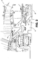
- the turbine engine 10 at least includes a bearing compartment 14, which contains oil that is to be maintained within the compartment. The bearing compartment 14 is more clearly illustrated in FIG. 2 .
- the bearing compartment 14 is defined in part by a stationary annular seal support 16 that extends from the engine casing 18 toward a rotatable turbine shaft 20 of the engine 10.
- the seal support 16 mounts to the casing 18 at various angularly spaced points with seal support mounting flanges 19 (only one such flange shown in FIG. 2 ).
- the positions of the mounting flanges 19 contribute to the positioning of secondary seals used to maintain a positive pressure differential relative to the bearing compartment 14.
- the seal support 16 further supports an annular bearing compartment seal assembly 22 that seals the bearing compartment and therefore limits leakage of oil from the compartment.
- the seal assembly 22 is more clearly illustrated in FIG. 3 .
- the bearing compartment seal assembly 22 comprises an annular seal member 24 that contacts an annular seal land 26 that is provided on an annular seal seat 28 that is supported by the turbine shaft 20 ( FIG. 2 ) and therefore is configured to rotate relative to the seal member.
- the seal member 24 is composed of carbon and the seal land 26 is composed of steel.
- the seal member 24 separates the bearing compartment 14 from an adjacent buffer air cavity 30.
- the buffer air cavity 30 is pressurized by air that is pumped into the cavity via openings 32 and 34 that are respectively provided in the turbine shaft 20 and a seal spacer 38.
- the buffer air cavity 30 is sealed by both the bearing compartment seal member 24 and secondary seals 40.
- the secondary seals 40 comprise annular knife edge seals. More particularly, a set of first knife edge seals 42 are provided on the turbine shaft 20 and a set of second knife edge seals 44 are provided on an annular seal ring 46, which is fixedly secured to the seal support 16.
- the seal ring 46 is mounted to the seal support 16 with a snap ring 48 that is held in place by a retainer member 50.
- small gaps 52 exist between the knife edge seals 42 and a seal land 54 provided on the seal ring 46.
- small gaps 56 exist between the knife edge seals 44 and a seal land 58 provided on the turbine shaft 20.
- the gaps 52, 56 represent the clearance of the knife edge seals 42, 44 that is to be controlled to ensure proper pressurization of the buffer air cavity 30.
- contact between the knife edge seals and their associated seal lands 54, 58 can result in the generation of debris that can adversely affect the engine 10 or its performance.
- a goal in engine design and assembly is to minimize/reduce the clearance of the knife edge seals 42, 44 through the entire circumference of the engine 10 while avoiding actual contact between the knife edge seals and their associated seal lands 54, 58.
- the seal ring 46 fits within an annular groove 60 provided in the seal support 16.
- the groove 60 is defined in part by an inner annular surface 62 that contacts or mates with an outer annular surface 64 of the seal ring 46.
- both annular surfaces 62, 64 are circular and have similar diameters such that the relative angular orientations of the seal support 16 and the seal ring 46 can be adjusted, i.e., the seal ring can be rotated within and relative to the seal support. As described below, such adjustment facilitates adjustment of the relative positions of the seal ring 46 and the turbine shaft 20, which thereby adjusts the size of the gaps 52, 56. This phenomenon can be better understood with reference to the schematic drawings of FIGs. 5A and 5B .
- FIG. 5A Shown in FIG. 5A is a schematic representation of the turbine shaft 20 as positioned within the seal ring 46.
- the gap 56 is visible (in exaggerated dimension) between the seal land 58 of the turbine shaft 20 and the edge of a second knife edge seal 44 of the seal ring 46.
- the seal ring 46 is properly aligned with the turbine shaft 20.
- the seal ring 46 is concentric with the turbine shaft 20. In such an arrangement, the gap 56 is uniform throughout the circumference of the engine 10 and therefore can be made smaller.
- the seal ring 46 is offset relative to the turbine shaft 20, for example due to tolerance accumulation. Therefore, even though the seal ring 46 and the turbine shaft 20 have been designed and manufactured so as to take engine tolerances into account, the result is relatively large clearance at one portion of the gap 56, i.e., near the 12 o'clock position in the example of FIG. 5B , which may permit air to escape relatively easily from the buffer air cavity 30 ( FIG. 4 ). In addition, the offset may result in undesired contact between the knife edge seals 44 and the seal land 58, as indicated at the 6 o'clock position in the example of FIG. 5B . From FIGs.
- FIG. 6 schematically illustrates an end view of the seal ring 46 as positioned within the seal support 16.
- the inner periphery of the seal ring 46 is defined by an inner annular surface 66, which coincides with the edges of the second knife edge seals 44.
- the outer periphery of the seal ring 46 is defined by the outer annular surface 64 first identified in FIG. 4 .
- both the inner annular surface 66 (i.e., the edges of the second knife edge seals 44) and outer annular surface 64 of the seal ring 46 are circular.
- the two circles defined by the outer annular surface 64 and inner annular surface 66 are non-concentric.
- the centers of those two circles are offset from each other such that the seal ring 46 has a larger radial dimension at some angular positions than at other angular positions.
- the seal ring 46 is largest at the 3 o'clock position and smallest at the 9 o'clock position.
- the seal support 16 is defined by the inner annular surface 62 first identified in FIG. 4 and outer periphery 68.
- the outer periphery 68 of the seal support 16 identifies the set of points at which the seal support 16 mounts to the engine casing, for example at the seal support mounting flanges 19 ( FIG. 2 ). It is that set of points that affects the position of the inner annular surface 62, of the seal support 16 and, therefore, the position of the seal ring 46.
- both the inner annular surface 62 and the outer periphery 68 are circular.
- the two circles defined by the inner annular surface 62 and the outer periphery 68 are non-concentric. Specifically, the centers of those two circles are offset from each other such that the seal support 16 has a radial dimension between its inner annular surface 62 and its outer periphery 68 that is greater at some angular positions than at other angular positions. In the example orientation shown in FIG. 6 , that dimension is largest at the 9 o'clock position and smallest at the 3 o'clock position.
- the position of the seal ring 46 can be adjusted for minimum clearance.
- Such adjustment affects not only the position of the second knife edge seals 44 but also the position of the seal land 54 ( FIG. 4 ).
- the positions of those elements affect the uniformity of the gaps 52 and 56 ( FIG. 4 ), and therefore the size of the gaps at discrete angular positions about the circumference of the engine 10.
- such adjustment can be performed during engine assembly. That way, the effects of tolerance accumulation can be observed (e.g., measured) and counteracted before engine service.
- FIGs. 7A and 7B An example of such adjustment is described in relation to FIGs. 7A and 7B below.
- each of the seal ring 46 and the seal support 16 are shown in exaggerated scale to emphasize the non-concentric or eccentric nature of their inner annular surfaces 66 and 62, respectively.
- the center of the circle that defines the inner annular surface 66 of the seal ring 46, and therefore the edges of the second knife edge seals 44 ( FIG. 4 ), is identified by crosshairs 70, while the centerline of the engine 10 ( FIG. 1 ) is identified by point 72.
- the center of the seal ring 46 is offset relative to the centerline of the engine 10, and therefore the centerline of the turbine shaft 20, for example due to tolerance accumulation.
- That offset represents a shift in the position of the second knife edge seals 44 and the seal land 54 that will decrease the uniformity of the gaps 52, 56 ( FIG. 4 ), which affects the extent to which the size of the gaps can be reduced.
- the position of the seal ring and its center 70 can be adjusted by adjusting the angular orientation of the seal ring or both of the seal ring and the seal support.
- the seal ring 46 or both of the seal ring 46 and seal support 16 can be rotated to "dial in” the center 70 to a desired position, which is coincident with the engine centerline 72.
- FIGs. 7A and 7B illustrate such adjustment in the counter-clockwise direction.
- the minimum dimension of the seal ring has been identified by reference A and the minimum dimension of the seal support has been identified by reference B.
- the minimum dimension A of the seal ring 46 is at the 3 o'clock position and the minimum dimension B of the seal support 16 is at the 9 o'clock position.
- the knife edge seal clearance can be made more uniform when the seal ring center 70 is moved toward the engine centerline 72.
- the seal ring center 70 is positioned down and to the left of the engine centerline 72 in the orientation of the drawing.
- the seal ring center 70 has been shifted up and to the right so as to coincide with the engine centerline 72.
- that shifting has been achieved by rotating the seal support 16 such that its minimum dimension B moved from the 9 o'clock position to approximately the 12 o'clock position. In practice, such rotation comprises rotating the seal support 16 within and relative to the engine casing 18 ( FIG. 2 ).
- the seal ring 46 has been rotated relative to the seal support such that, after rotation of both the seal ring and the seal support, the minimum dimension of the seal ring moved from the 3 o'clock position to approximately the 4 o'clock position.
- the location of the center of the seal ring 46, and therefore the location of the second knife edge seals 44 and the seal land 54 can be adjusted by changing the angular orientation of the seal support 16 relative to the engine casing 18 and changing the angular orientation of the seal ring relative to the seal support.
- the seal ring 46 and the seal support 16 can be fixed in place to prevent subsequent movement , with the seal support mounting to the engine casing 18 and the seal ring mounting to the seal support.
- the number of positions at which the seal ring center 70 can be positioned is substantially infinite in cases in which angular orientation of the seal ring 46 and/or the seal support 16 is substantially infinitely adjustable.
- seal ring 46 and/or the seal support 16 can only be secured in predetermined angular orientations, for example due to the positions of mounting features (e.g., mounting flanges, lug slots) that are used to secure the seal ring and/or the seal support, adjustment of the seal ring center is finite and can be "indexed” or “clocked” by alternative alignment of the mounting features.
- mounting features e.g., mounting flanges, lug slots
- the offset between the seal ring center and the engine centerline can be determined by a mechanic charged with engine assembly.
- the mechanic can use engine-specific tooling in concert with traditional inspection gauges to measure any offset between the seal ring and the engine centerline.
- the mechanic can then rotate the seal ring 46 within the seal support 16 and rotate the seal support inside engine casing 18 (in that order or reverse order) according to a specific indexing pattern with the intention of mitigating the accumulated tolerance.
- an indexing pattern can comprise a series of indicator marks provided along the outside of seal ring 46 and the seal support 16.
- An appropriate algorithm can then aid the mechanic in aligning the marks in the proper orientation to mitigate the accumulated tolerance.
- Such an algorithm can combine the manufacturing tolerances of the seal support 16, engine casing 18, seal ring 46, as well as overall engine assembly.
- the mechanic can perform a confirmation of the adjustment to ensure that the indicated orientations were correct.
- Such confirmation can be performed, for example, by using a feeler gauge or similar device that measures the gaps between the knife edge seals and their associated seal lands to confirm that the gaps are of a desired uniformity and size around the circumference of the engine.
Landscapes
- Engineering & Computer Science (AREA)
- Mechanical Engineering (AREA)
- General Engineering & Computer Science (AREA)
- Chemical & Material Sciences (AREA)
- Combustion & Propulsion (AREA)
- Turbine Rotor Nozzle Sealing (AREA)
Claims (15)
- Procédé pour contrôler le jeu d'étanchéité dans un moteur de turbine (10), le procédé comprenant :le positionnement d'une bague d'étanchéité (46) à l'intérieur du moteur de turbine, la bague d'étanchéité (46) ayant une surface annulaire interne (66) et une surface annulaire externe (64), la surface annulaire interne (66) et la surface annulaire externe (64) étant toutes deux circulaires mais non concentriques ;la rotation de la bague d'étanchéité (46) à l'intérieur du moteur jusqu'à ce que la bague d'étanchéité (46) soit placée dans une orientation alignée dans laquelle un centre d'un cercle qui définit la surface annulaire interne (66) coïncide avec une ligne centrale (72) du moteur de turbine ; etla fixation de la bague d'étanchéité (46) dans l'orientation alignée.
- Procédé selon la revendication 1, dans lequel la surface annulaire interne (66) est définie par un bord d'au moins un joint d'étanchéité en arête de couteau de la bague d'étanchéité (46).
- Procédé selon la revendication 1 ou 2, dans lequel le positionnement de la bague d'étanchéité (46) comprend le positionnement de la bague d'étanchéité (46) à l'intérieur d'une rainure annulaire (60) d'un support d'étanchéité (16) de sorte que la surface annulaire externe (64) entre en contact avec une surface annulaire interne (62) de la rainure (60).
- Procédé selon une quelconque revendication précédente, comprenant en outre :le positionnement d'un support d'étanchéité (16) à l'intérieur du moteur de turbine, le support d'étanchéité (16) ayant une surface annulaire interne (62) conçue pour recevoir la bague d'étanchéité (46) et une périphérie externe (68) au niveau de laquelle le support d'étanchéité (16) est monté sur le moteur, la surface annulaire interne (62) et la périphérie externe (68) du support d'étanchéité (16) étant toutes deux circulaires mais non concentriques ;la rotation également du support d'étanchéité (16) par rapport au moteur ; etla fixation du support d'étanchéité (16) au moteur.
- Procédé selon la revendication 4, dans lequel la surface annulaire externe (64) de la bague d'étanchéité (46) entre en contact avec la surface annulaire interne (62) du support d'étanchéité (16) lorsque la bague d'étanchéité (46) est reçue par le support d'étanchéité (16).
- Procédé selon une quelconque revendication précédente, comprenant en outre la détermination d'un décalage entre la bague d'étanchéité (46) et la ligne centrale du moteur (72).
- Procédé selon la revendication 1, le procédé comprenant en outre :le positionnement d'un support d'étanchéité (16) à l'intérieur d'un carter (18) du moteur de turbine (10), le support d'étanchéité (16) ayant une surface annulaire interne (62) conçue pour recevoir la bague d'étanchéité (46) et une périphérie externe (68) au niveau de laquelle le support d'étanchéité (16) est monté sur le carter (18), la surface annulaire interne (62) et la périphérie externe (68) étant toutes deux circulaires mais non concentriques de sorte que le support d'étanchéité (16) a une dimension radiale relativement grande dans une première position angulaire et une dimension radiale relativement petite dans une seconde position angulaire ;la bague d'étanchéité (46) ayant une dimension radiale relativement grande dans une première position angulaire et une dimension radiale relativement petite dans une seconde position angulaire ;la rotation du support d'étanchéité (16) par rapport au carter et la rotation de la bague d'étanchéité (46) par rapport au support d'étanchéité (16) jusqu'à ce que la bague d'étanchéité (46) soit placée dans l'orientation alignée ; etla fixation du support d'étanchéité (16) au carter et la fixation de la bague d'étanchéité (46) au support d'étanchéité (16) tandis que le support d'étanchéité (16) est dans l'orientation alignée.
- Procédé selon la revendication 7, dans lequel la surface annulaire interne (66) de la bague d'étanchéité (46) est définie par des bords de joints d'étanchéité en arête de couteau (44) de la bague d'étanchéité (46).
- Procédé selon la revendication 7 ou 8, dans lequel le positionnement de la bague d'étanchéité (46) comprend la mise en contact de la surface annulaire externe (64) de la bague d'étanchéité (46) avec la surface annulaire interne (62) du support d'étanchéité (16).
- Moteur de turbine (10), comprenant :un carter de moteur (18) ;un support d'étanchéité (16) conçu pour être monté sur le carter de moteur (18), le support d'étanchéité (16) ayant une surface annulaire interne (62) conçue pour recevoir une bague d'étanchéité (46) et une périphérie externe (68) au niveau de laquelle le support d'étanchéité (16) est monté sur le carter du moteur, la surface annulaire interne (62) et la périphérie externe (68) étant toutes deux circulaires mais non concentriques ; etune bague d'étanchéité (46) conçue pour être montée sur le support d'étanchéité (16), la bague d'étanchéité (46) ayant une surface annulaire interne (66) et une surface annulaire externe (64), la surface annulaire interne (68) et la surface annulaire externe (64) de la bague d'étanchéité (46) étant toutes deux circulaires mais non concentriques ;moyennant quoi un centre d'un cercle qui définit la surface annulaire interne (68) de la bague d'étanchéité (46) peut être ajusté pour coïncider avec une ligne centrale (72) du moteur de turbine (10) par la rotation du support d'étanchéité (16) par rapport au carter de moteur et la rotation de la bague d'étanchéité (46) par rapport au support d'étanchéité (16) pour lutter contre l'accumulation de tolérance.
- Moteur de turbine selon la revendication 10, dans lequel la bague d'étanchéité (46) comprend des joints d'étanchéité en arête de couteau (44) et dans lequel des bords des joints d'étanchéité en arête de couteau (44) définissent la surface annulaire interne (66) de la bague d'étanchéité (46), et/ou dans lequel la bague d'étanchéité (46) comprend une zone d'étanchéité (54) qui est conçue pour être opposée à des joints d'étanchéité en arête de couteau (42) prévus sur un arbre de turbine du moteur.
- Moteur de turbine selon la revendication 10 ou 11, dans lequel la bague d'étanchéité (46) est montée à l'intérieur d'une rainure annulaire (60) du support d'étanchéité (16) et dans lequel la surface annulaire externe (64) de la bague d'étanchéité (46) entre en contact avec la surface annulaire interne (62) du support d'étanchéité (16) lorsque la bague d'étanchéité (46) est positionnée à l'intérieur de la rainure annulaire (60).
- Moteur de turbine selon la revendication 10, 11 ou 12, dans lequel le moteur comprend des brides de montage (19) prévues sur un carter de moteur (18) sur lequel le support d'étanchéité (18) est monté.
- Moteur de turbine selon l'une quelconque des revendications 10 à 13, comprenant en outre des éléments de montage qui fixent la bague d'étanchéité (46) au support d'étanchéité (16).
- Moteur de turbine (10) selon la revendication 10, dans lequel :la surface annulaire externe (64) de la bague d'étanchéité (46) entre en contact avec la surface annulaire interne (62) du support d'étanchéité (16) lorsque la bague d'étanchéité (46) est montée sur le support d'étanchéité (16) ;la bague d'étanchéité (46) comprend en outre des joints d'étanchéité en arête de couteau (44), dans lequel un premier cercle qui définit la surface annulaire externe (64) et un second cercle qui définit des bords des joints d'étanchéité en arête de couteau (44) sont non concentriques ; et comprenant en outreun arbre de turbine ayant une zone d'étanchéité (54) conçue à l'opposé des joints d'étanchéité en arête de couteau (44) de la bague d'étanchéité (46) de sorte que la zone d'étanchéité (54) et les joints d'étanchéité en arête de couteau (44) sont séparés par un espace (56) ;moyennant quoi le support d'étanchéité (16) peut être entraîné en rotation par rapport au carter de moteur (18) et la bague d'étanchéité (46) peut être entraînée en rotation par rapport au support d'étanchéité (16) pour augmenter l'uniformité de l'espace (56) entre la zone d'étanchéité d'arbre de turbine (54) et les joints d'étanchéité en arête de couteau de bague d'étanchéité (44).
Applications Claiming Priority (1)
| Application Number | Priority Date | Filing Date | Title |
|---|---|---|---|
| US11/931,149 US7878756B2 (en) | 2007-10-31 | 2007-10-31 | Systems and methods for controlling seal clearance in a turbine engine |
Publications (3)
| Publication Number | Publication Date |
|---|---|
| EP2055899A2 EP2055899A2 (fr) | 2009-05-06 |
| EP2055899A3 EP2055899A3 (fr) | 2012-11-07 |
| EP2055899B1 true EP2055899B1 (fr) | 2020-01-15 |
Family
ID=40303521
Family Applications (1)
| Application Number | Title | Priority Date | Filing Date |
|---|---|---|---|
| EP08253539.4A Ceased EP2055899B1 (fr) | 2007-10-31 | 2008-10-29 | Systèmes et procédés pour contrôler le jeu d'étanchéité dans un moteur de turbine |
Country Status (2)
| Country | Link |
|---|---|
| US (1) | US7878756B2 (fr) |
| EP (1) | EP2055899B1 (fr) |
Families Citing this family (14)
| Publication number | Priority date | Publication date | Assignee | Title |
|---|---|---|---|---|
| FR2983518B1 (fr) * | 2011-12-06 | 2014-02-07 | Snecma | Dispositif deverrouillable d'arret axial d'une couronne d'etancheite contactee par une roue mobile de module de turbomachine d'aeronef |
| US9869249B2 (en) | 2012-01-31 | 2018-01-16 | United Technologies Corporation | Speed sensor probe location in gas turbine engine |
| US9309775B2 (en) * | 2012-05-21 | 2016-04-12 | United Technologies Corporation | Rotational debris discourager for gas turbine engine bearing |
| US9163522B2 (en) | 2012-08-21 | 2015-10-20 | United Technologies Corporation | Spring carrier and removable seal carrier |
| EP3628822B1 (fr) * | 2014-10-30 | 2022-05-04 | Raytheon Technologies Corporation | Systèmes d' étanchéité |
| US10487943B2 (en) | 2016-07-12 | 2019-11-26 | United Technologies Corporation | Multi-ply seal ring |
| US10662941B2 (en) * | 2017-01-18 | 2020-05-26 | Q.E.D. Environmental Systems, Inc. | Modular pneumatic well pump system |
| US10677082B2 (en) | 2017-05-26 | 2020-06-09 | Pratt & Whitney Canada Corp. | Axially compact pressurized seal |
| DE102018119463B4 (de) | 2018-08-09 | 2023-12-28 | Rolls-Royce Deutschland Ltd & Co Kg | Labyrinthdichtungssystem und Gasturbinentriebwerk mit einem Labyrinthdichtungssystem |
| US11248492B2 (en) * | 2019-03-18 | 2022-02-15 | Raytheon Technologies Corporation | Seal assembly for a gas turbine engine |
| US11629649B2 (en) | 2020-05-11 | 2023-04-18 | Raytheon Technologies Corporation | Gas turbine engine with speed sensor |
| US11415062B2 (en) | 2020-11-18 | 2022-08-16 | Raytheon Technologies Corporation | Rotating sleeve controlling clearance of seal assembly of gas turbine engine |
| GB202203012D0 (en) | 2022-03-04 | 2022-04-20 | Rolls Royce Plc | Brush seal |
| US12091980B1 (en) | 2023-12-13 | 2024-09-17 | Honeywell International Inc. | Spring biased shroud retention system for gas turbine engine |
Family Cites Families (20)
| Publication number | Priority date | Publication date | Assignee | Title |
|---|---|---|---|---|
| US3385624A (en) * | 1966-04-20 | 1968-05-28 | Baclini David | Eccentric adjusting device |
| US4035044A (en) * | 1976-06-17 | 1977-07-12 | Sadao Miyazaki | Bearing assembly |
| US4222708A (en) * | 1978-06-26 | 1980-09-16 | General Electric Company | Method and apparatus for reducing eccentricity in a turbomachine |
| FR2515734A1 (fr) * | 1981-11-05 | 1983-05-06 | Snecma | Systeme d'ajustement du centrage d'une roue de turbomachine et turbomachine munie de moyens permettant l'application dudit systeme |
| US4406460A (en) | 1982-11-01 | 1983-09-27 | United Technologies Corporation | Anti-weepage valve for rotating seals |
| US4709545A (en) | 1983-05-31 | 1987-12-01 | United Technologies Corporation | Bearing compartment protection system |
| JPS61286503A (ja) * | 1985-06-12 | 1986-12-17 | Toshiba Corp | 蒸気タ−ビンのラビリンスシ−ル装置 |
| US4928978A (en) | 1988-04-07 | 1990-05-29 | United Technologies Corporation | Rotating shaft seal |
| EP0382333B1 (fr) * | 1989-01-09 | 1993-06-30 | Northern Engineering Industries Plc | Arrangement des éléments en forme de segment dans des machines rotoriques |
| US5630590A (en) | 1996-03-26 | 1997-05-20 | United Technologies Corporation | Method and apparatus for improving the airsealing effectiveness in a turbine engine |
| US6623238B2 (en) * | 1998-08-21 | 2003-09-23 | Honeywell International, Inc. | Air turbine starter with seal assembly |
| US6682307B1 (en) | 1999-05-14 | 2004-01-27 | Siemens Aktiengesellschaft | Sealing system for a rotor of a turbo engine |
| US6309177B1 (en) * | 1999-06-08 | 2001-10-30 | Pratt & Whitney Canada Corp. | Concentricity ring |
| US6382632B1 (en) * | 2001-02-21 | 2002-05-07 | General Electric Company | Repositionable brush seal for turbomachinery |
| US7001145B2 (en) | 2003-11-20 | 2006-02-21 | General Electric Company | Seal assembly for turbine, bucket/turbine including same, method for sealing interface between rotating and stationary components of a turbine |
| US7407369B2 (en) | 2004-12-29 | 2008-08-05 | United Technologies Corporation | Gas turbine engine blade tip clearance apparatus and method |
| US7175388B2 (en) * | 2005-04-21 | 2007-02-13 | Pratt & Whitney Canada Corp. | Integrated labyrinth and carbon seal |
| US7510374B2 (en) * | 2005-07-28 | 2009-03-31 | Honeywell International Inc. | Non-concentric rings for reduced turbo-machinery operating clearances |
| US8517666B2 (en) | 2005-09-12 | 2013-08-27 | United Technologies Corporation | Turbine cooling air sealing |
| US7967560B2 (en) * | 2006-11-07 | 2011-06-28 | United Technologies Corporation | Radially energized oil capture device for a geared turbofan |
-
2007
- 2007-10-31 US US11/931,149 patent/US7878756B2/en not_active Expired - Fee Related
-
2008
- 2008-10-29 EP EP08253539.4A patent/EP2055899B1/fr not_active Ceased
Non-Patent Citations (1)
| Title |
|---|
| None * |
Also Published As
| Publication number | Publication date |
|---|---|
| EP2055899A2 (fr) | 2009-05-06 |
| US7878756B2 (en) | 2011-02-01 |
| US20090110545A1 (en) | 2009-04-30 |
| EP2055899A3 (fr) | 2012-11-07 |
Similar Documents
| Publication | Publication Date | Title |
|---|---|---|
| EP2055899B1 (fr) | Systèmes et procédés pour contrôler le jeu d'étanchéité dans un moteur de turbine | |
| US11828185B2 (en) | Steam turbine seal clearance adjusting method | |
| EP2964886B1 (fr) | Agencement de disque et procédé de retenue de deux éléments rotatifs séparés d'un moteur à turbine à gaz | |
| US4222708A (en) | Method and apparatus for reducing eccentricity in a turbomachine | |
| US10677074B2 (en) | Method for carrying out work on a rotor and associated foil | |
| EP2036646A1 (fr) | Procédé pour la réparation d'un composant de moteur de turbine | |
| CN102046921B (zh) | 固定转子或定子部件的环形法兰 | |
| EP2358976B1 (fr) | Compresseur a spirales | |
| EP1185766B1 (fr) | Segment de concentricite | |
| EP2803883B1 (fr) | Dispositif d'étanchéité d'arbre et machine rotative dotée de ce dernier | |
| US12281591B2 (en) | T-fairing installation tooling assembly | |
| US10900367B2 (en) | Sealing unit for turbocharger | |
| CN113530621B (zh) | 用于组装和装运蒸汽涡轮的系统和方法 | |
| US10837309B2 (en) | Retention clip for variable vane arm | |
| EP3527786B1 (fr) | Procédé et appareil de modification d'un élément d'étanchéité statorique de turbomachine | |
| CN113614402B (zh) | 推力箔片轴承、箔片轴承单元、涡轮机械以及箔片 | |
| US7510374B2 (en) | Non-concentric rings for reduced turbo-machinery operating clearances | |
| US12084989B2 (en) | Curvature adjustment method for stator blade segment, method for manufacturing stationary body of axial-flow rotary machine, and curvature adjustment jig for stator blade segment | |
| JP2016191597A (ja) | バランス検査装置 | |
| US10436047B2 (en) | Method for repair of a diaphragm of a rotary machine | |
| KR20250168281A (ko) | 날개 각도 측정 장치, 및 이것을 이용한 날개 각도 측정 방법 |
Legal Events
| Date | Code | Title | Description |
|---|---|---|---|
| PUAI | Public reference made under article 153(3) epc to a published international application that has entered the european phase |
Free format text: ORIGINAL CODE: 0009012 |
|
| AK | Designated contracting states |
Kind code of ref document: A2 Designated state(s): AT BE BG CH CY CZ DE DK EE ES FI FR GB GR HR HU IE IS IT LI LT LU LV MC MT NL NO PL PT RO SE SI SK TR |
|
| AX | Request for extension of the european patent |
Extension state: AL BA MK RS |
|
| PUAL | Search report despatched |
Free format text: ORIGINAL CODE: 0009013 |
|
| AK | Designated contracting states |
Kind code of ref document: A3 Designated state(s): AT BE BG CH CY CZ DE DK EE ES FI FR GB GR HR HU IE IS IT LI LT LU LV MC MT NL NO PL PT RO SE SI SK TR |
|
| AX | Request for extension of the european patent |
Extension state: AL BA MK RS |
|
| RIC1 | Information provided on ipc code assigned before grant |
Ipc: F01D 25/18 20060101ALI20121004BHEP Ipc: F01D 11/02 20060101AFI20121004BHEP Ipc: F02C 7/28 20060101ALI20121004BHEP |
|
| 17P | Request for examination filed |
Effective date: 20130507 |
|
| RBV | Designated contracting states (corrected) |
Designated state(s): DE GB |
|
| RAP1 | Party data changed (applicant data changed or rights of an application transferred) |
Owner name: UNITED TECHNOLOGIES CORPORATION |
|
| STAA | Information on the status of an ep patent application or granted ep patent |
Free format text: STATUS: EXAMINATION IS IN PROGRESS |
|
| 17Q | First examination report despatched |
Effective date: 20171023 |
|
| GRAP | Despatch of communication of intention to grant a patent |
Free format text: ORIGINAL CODE: EPIDOSNIGR1 |
|
| STAA | Information on the status of an ep patent application or granted ep patent |
Free format text: STATUS: GRANT OF PATENT IS INTENDED |
|
| INTG | Intention to grant announced |
Effective date: 20190603 |
|
| GRAJ | Information related to disapproval of communication of intention to grant by the applicant or resumption of examination proceedings by the epo deleted |
Free format text: ORIGINAL CODE: EPIDOSDIGR1 |
|
| STAA | Information on the status of an ep patent application or granted ep patent |
Free format text: STATUS: EXAMINATION IS IN PROGRESS |
|
| GRAP | Despatch of communication of intention to grant a patent |
Free format text: ORIGINAL CODE: EPIDOSNIGR1 |
|
| STAA | Information on the status of an ep patent application or granted ep patent |
Free format text: STATUS: GRANT OF PATENT IS INTENDED |
|
| INTC | Intention to grant announced (deleted) | ||
| GRAS | Grant fee paid |
Free format text: ORIGINAL CODE: EPIDOSNIGR3 |
|
| GRAA | (expected) grant |
Free format text: ORIGINAL CODE: 0009210 |
|
| STAA | Information on the status of an ep patent application or granted ep patent |
Free format text: STATUS: THE PATENT HAS BEEN GRANTED |
|
| INTG | Intention to grant announced |
Effective date: 20191118 |
|
| AK | Designated contracting states |
Kind code of ref document: B1 Designated state(s): DE GB |
|
| REG | Reference to a national code |
Ref country code: GB Ref legal event code: FG4D |
|
| REG | Reference to a national code |
Ref country code: DE Ref legal event code: R096 Ref document number: 602008062005 Country of ref document: DE |
|
| REG | Reference to a national code |
Ref country code: DE Ref legal event code: R097 Ref document number: 602008062005 Country of ref document: DE |
|
| PLBE | No opposition filed within time limit |
Free format text: ORIGINAL CODE: 0009261 |
|
| STAA | Information on the status of an ep patent application or granted ep patent |
Free format text: STATUS: NO OPPOSITION FILED WITHIN TIME LIMIT |
|
| 26N | No opposition filed |
Effective date: 20201016 |
|
| REG | Reference to a national code |
Ref country code: DE Ref legal event code: R081 Ref document number: 602008062005 Country of ref document: DE Owner name: RAYTHEON TECHNOLOGIES CORPORATION (N.D.GES.D.S, US Free format text: FORMER OWNER: UNITED TECHNOLOGIES CORPORATION, FARMINGTON, CONN., US |
|
| PGFP | Annual fee paid to national office [announced via postgrant information from national office to epo] |
Ref country code: DE Payment date: 20220616 Year of fee payment: 15 |
|
| PGFP | Annual fee paid to national office [announced via postgrant information from national office to epo] |
Ref country code: GB Payment date: 20230920 Year of fee payment: 16 |
|
| REG | Reference to a national code |
Ref country code: DE Ref legal event code: R119 Ref document number: 602008062005 Country of ref document: DE |
|
| PG25 | Lapsed in a contracting state [announced via postgrant information from national office to epo] |
Ref country code: DE Free format text: LAPSE BECAUSE OF NON-PAYMENT OF DUE FEES Effective date: 20240501 |
|
| GBPC | Gb: european patent ceased through non-payment of renewal fee |
Effective date: 20241029 |
|
| PG25 | Lapsed in a contracting state [announced via postgrant information from national office to epo] |
Ref country code: GB Free format text: LAPSE BECAUSE OF NON-PAYMENT OF DUE FEES Effective date: 20241029 |