EP2055903B1 - Leitschaufelanordnung mit variabler Geometrie für eine Gasturbine - Google Patents
Leitschaufelanordnung mit variabler Geometrie für eine Gasturbine Download PDFInfo
- Publication number
- EP2055903B1 EP2055903B1 EP08253338.1A EP08253338A EP2055903B1 EP 2055903 B1 EP2055903 B1 EP 2055903B1 EP 08253338 A EP08253338 A EP 08253338A EP 2055903 B1 EP2055903 B1 EP 2055903B1
- Authority
- EP
- European Patent Office
- Prior art keywords
- platform
- inner diameter
- assembly
- diameter platform
- vane
- Prior art date
- Legal status (The legal status is an assumption and is not a legal conclusion. Google has not performed a legal analysis and makes no representation as to the accuracy of the status listed.)
- Active
Links
Images

Classifications
-
- F—MECHANICAL ENGINEERING; LIGHTING; HEATING; WEAPONS; BLASTING
- F01—MACHINES OR ENGINES IN GENERAL; ENGINE PLANTS IN GENERAL; STEAM ENGINES
- F01D—NON-POSITIVE DISPLACEMENT MACHINES OR ENGINES, e.g. STEAM TURBINES
- F01D17/00—Regulating or controlling by varying flow
- F01D17/10—Final actuators
- F01D17/12—Final actuators arranged in stator parts
- F01D17/14—Final actuators arranged in stator parts varying effective cross-sectional area of nozzles or guide conduits
- F01D17/16—Final actuators arranged in stator parts varying effective cross-sectional area of nozzles or guide conduits by means of nozzle vanes
- F01D17/162—Final actuators arranged in stator parts varying effective cross-sectional area of nozzles or guide conduits by means of nozzle vanes for axial flow, i.e. the vanes turning around axes which are essentially perpendicular to the rotor centre line
-
- F—MECHANICAL ENGINEERING; LIGHTING; HEATING; WEAPONS; BLASTING
- F05—INDEXING SCHEMES RELATING TO ENGINES OR PUMPS IN VARIOUS SUBCLASSES OF CLASSES F01-F04
- F05D—INDEXING SCHEME FOR ASPECTS RELATING TO NON-POSITIVE-DISPLACEMENT MACHINES OR ENGINES, GAS-TURBINES OR JET-PROPULSION PLANTS
- F05D2240/00—Components
- F05D2240/10—Stators
- F05D2240/11—Shroud seal segments
Definitions
- US 4,013,377 discloses a vane assembly for a gas turbine engine with the features of the preamble of claim 1.
- US 3,224,194 discloses a gas turbine engine with adjustable nozzle blades.
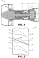
- FIG. 1 is a schematic diagram depicting an exemplary embodiment of a gas turbine engine.
- engine 100 incorporates a fan 102, a compressor section 104, a combustion section 106 and a turbine section 108.
- Engine 100 also incorporates a variable vane assembly 110.
- FIG. 1 depicted in FIG. 1 as being positioned between a low-pressure turbine and a high-pressure turbine, various other locations of a variable vane assembly can be used in other embodiments.
- FIG. 1 depicted in FIG. 1 as a turbofan gas turbine engine, there is no intention to limit the concepts described herein to use with turbofans as other types of gas turbine engines can be used.
- vane assembly 110 includes an annular arrangement of vanes positioned about a longitudinal axis 112.
- Inner and outer diameter platforms of the vanes mount vane airfoils.
- vanes 120 and 130 include inner diameter platforms 122, 132, respectively, and outer diameter platforms 124, 134 respectively.
- Vane airfoils e.g., airfoil 1366
- airfoil 136 extends beyond the periphery of platforms 132, 134.
- an inner platform gap 126 between adjacent inner platforms 122, 132, and an outer platform gap 128 is located between adjacent outer platforms 124, 134.
- Airfoil 136 obstructs at least a portion of each of the gaps.
- the length of the gap spanned can be as much as a chord length of the airfoil.
- the vane length of the gaps being spanned can vary depending upon the rotational positioning of the airfoil.
- the gap can be oriented in various manners relative to the longitudinal axis of the engine. For instance, in the embodiment of FIG. 2 , the gap is not parallel with longitudinal axis 112.
- the vane airfoils 152, 154 extend between an inner diameter platform 156 and an outer diameter platform 158.
- Platform 156 includes an inner diameter surface 160, an outer diameter surface 161, a forward edge 162, an aft edge 164, and side edges 166, 168 that extend between the forward and aft edges.
- Platform 158 includes an inner diameter surface 170, an outer diameter surface 171, a forward edge 172, an aft edge 174, and side edges 176, 178 that extend between the forward and aft edges.
- the sweep of the trailing edge 191 of the variable vane can be contained within the vane 150.
- Such a configuration tends to ensure that vane-to-vane variations do not affect the leak path located between adjacent vanes.
- bearing 224 can be configured as a cartridge bearing and/or contain a spherical bearing. It should be noted that by providing a spherical surface, misalignment of the inner diameter and outer diameter platforms should not induce a bending moment on the airfoil 154.
- vanes typically are configured in an annular arrangement of vanes to form a vane assembly.
- the vane assembly defines an annular gas flow path between the vanes and platforms.
- Multiple vanes similar in construction to vane 150 can be provided in such an assembly.
- the annular arrangement includes alternating stationary and variable airfoils.
- variable vane is configured as a removable portion of the vane assembly
- the variable vane can be separately formed from the assembly. This can result in relative ease of manufacture.
- various materials can be used to form a variable vane and/or associated vane airfoil such as ceramic, Ceramic Matrix Composite (CMC), metals.
Landscapes
- Engineering & Computer Science (AREA)
- Mechanical Engineering (AREA)
- General Engineering & Computer Science (AREA)
- Turbine Rotor Nozzle Sealing (AREA)
- Structures Of Non-Positive Displacement Pumps (AREA)
- Control Of Turbines (AREA)
Claims (13)
- Leitschaufelanordnung für ein Gasturbinentriebwerk, Folgendes umfassend:eine erste Innendurchmesserebene (156);eine erste Außendurchmesserebene (158), die von der ersten Innendurchmesserebene (156) beabstandet ist; undein variables Schaufelprofil (154), das drehbar an der ersten Innendurchmesserebene (156) und der ersten Außendurchmesserebene (158) angebracht ist und sich so zwischen beiden erstreckt, dass sich wenigstens ein Abschnitt des Schaufelprofils (154) außerhalb einer Peripherie von wenigstens einer der ersten Innendurchmesserebene (156) und der ersten Außendurchmesserebene (158) erstreckt, wobei die erste Innendurchmesserebene (156) eine Außendurchmesserfläche (161) aufweist;dadurch gekennzeichnet, dass die erste Innendurchmesserebene (156) eine Vertiefung (180) in der Außendurchmesserfläche aufweist, die konfiguriert ist, um das entsprechende Ende des variablen Schaufelprofils aufzunehmen; undeinen Schaufelgrund (184) des Schaufelprofils (154), der sich in die Vertiefung (180) erstreckt.
- Anordnung nach Anspruch 1, wobei:sowohl die erste Innendurchmesserebene (156) als auch die erste Außendurchmesserebene (158) eine Vorderkante (162; 172), eine Hinterkante (164; 174) und eine Seitenkante (168; 178), die sich zwischen der Vorder- und der Hinterkante erstreckt, aufweist; undsich wenigstens ein Abschnitt des Schaufelprofils (154) über die Seitenkante (168; 178) von wenigstens einer der ersten Innendurchmesserebene (156) und der ersten Außendurchmesserebene (158) hinaus erstreckt.
- Anordnung nach Anspruch 1 oder 2, wobei:die Vertiefung (180) eine Ansaugseitenvertiefung ist; undsich wenigstens ein Abschnitt des Schaufelgrunds (184), der mit einer Ansaugseite des Schaufelprofils (154) verbunden ist, in die Ansaugseitenvertiefung (180) erstreckt.
- Anordnung nach einem der vorhergehenden Ansprüche, ferner umfassend:eine zweite Innendurchmesserebene; undeine zweite Außendurchmesserebene, die von der zweiten Innendurchmesserebene beabstandet ist;wobei die zweite Innendurchmesserebene neben der ersten Innendurchmesserebene (156) positioniert ist, so dass dazwischen eine innere Ebenenlücke geformt ist;wobei die zweite Außendurchmesserebene neben der ersten Außendurchmesserebene (158) positioniert ist, so dass dazwischen eine äußere Ebenenlücke geformt ist;wobei sich das Schaufelprofil (154) über wenigstens einen Abschnitt der inneren Ebenenlücke und über wenigstens einen Abschnitt der äußeren Ebenenlücke erstreckt.
- Anordnung nach Anspruch 4, wobei:die zweite Innendurchmesserebene eine Druckseitenvertiefung aufweist; undwenigstens ein Abschnitt des mit der Druckseite des Schaufelprofils verbundenen Schaufelgrunds sich in die Druckseitenvertiefung erstreckt.
- Anordnung nach einem der vorhergehenden Ansprüche, wobei:das Schaufelprofil (154) ein erstes Schaufelprofil ist; unddie Anordnung ferner einen zweites Schaufelprofil (152) umfasst, das sich zwischen der ersten Innendurchmesserebene (156) und der ersten Außendurchmesserebene (158) erstreckt.
- Anordnung nach Anspruch 6, wobei das zweite Schaufelprofil (152) ein feststehendes Profil ist, das gegenüber der ersten Innendurchmesserebene (156) und der ersten Außendurchmesserebene (158) befestigt ist.
- Anordnung nach einem der vorhergehenden Ansprüche, wobei das Schaufelprofil (152) ein Abschnitt einer Leitschaufelanordnung mit variabler Geometrie (200) ist, die einen Schaft (202), vorzugsweise mit einer konischen Kerbverzahnung (206), aufweist, wobei das Schaufelprofil (154) so am Schaft (202) angebracht ist, dass das Profil mit dem Schaft rotiert.
- Anordnung nach Anspruch 8, wobei:die erste Innendurchmesserebene (156) ein erstes Innendurchmesserkugellager (224) trägt; undein freiliegendes Ende (226) des Schafts (202) vom Innendurchmesserkugellager (224) aufgenommen wird.
- Anordnung nach Anspruch 8 oder 9, wobei:die Leitschaufelanordnung mit variabler Geometrie (200) ferner ein mit dem Schaft (202) verbundenes Stehlager (204) umfasst;die erste Außendurchmesserebene (158) dazu dient, das Stehlager (204) aufzunehmen.
- Anordnung nach einem der Ansprüche 8 bis 10, wobei der Schaft (202) ein hohler Schaft ist, der dazu dient, Kühlluft zum Kühlen des Schaufelprofils (152) zu empfangen.
- Anordnung nach einem der vorhergehenden Ansprüche, wobei:die erste Außendurchmesserebene (158) eine Innendurchmesserfläche (170) und eine sich in der Innendurchmesserfläche befindliche Vertiefung (186) aufweist; undsich eine Spitze (190) des Schaufelprofils (154) in die Vertiefung (186) erstreckt.
- Gasturbinentriebwerk, umfassend:einen Kompressor (104);eine Brennkammer (106), die dazu dient, Druckluft vom Kompressor (104) zu empfangen;eine Turbine (108), die den Kompressor (104) antreibt, wobei die Turbine eine Leitschaufelanordnung nach einem der vorhergehenden Ansprüche aufweist.
Applications Claiming Priority (1)
| Application Number | Priority Date | Filing Date | Title |
|---|---|---|---|
| US11/872,156 US8202043B2 (en) | 2007-10-15 | 2007-10-15 | Gas turbine engines and related systems involving variable vanes |
Publications (3)
| Publication Number | Publication Date |
|---|---|
| EP2055903A2 EP2055903A2 (de) | 2009-05-06 |
| EP2055903A3 EP2055903A3 (de) | 2012-01-18 |
| EP2055903B1 true EP2055903B1 (de) | 2018-12-05 |
Family
ID=40193693
Family Applications (1)
| Application Number | Title | Priority Date | Filing Date |
|---|---|---|---|
| EP08253338.1A Active EP2055903B1 (de) | 2007-10-15 | 2008-10-15 | Leitschaufelanordnung mit variabler Geometrie für eine Gasturbine |
Country Status (2)
| Country | Link |
|---|---|
| US (1) | US8202043B2 (de) |
| EP (1) | EP2055903B1 (de) |
Families Citing this family (78)
| Publication number | Priority date | Publication date | Assignee | Title |
|---|---|---|---|---|
| US8262345B2 (en) * | 2009-02-06 | 2012-09-11 | General Electric Company | Ceramic matrix composite turbine engine |
| FR2948965B1 (fr) * | 2009-08-06 | 2012-11-30 | Snecma | Etage redresseur pour une turbomachine |
| SG182525A1 (en) | 2010-01-15 | 2012-08-30 | Skyventure Internat Ltd | Wind tunnel turning vane heat exchanger |
| DE102010021145A1 (de) * | 2010-05-21 | 2011-11-24 | Mtu Aero Engines Gmbh | Verstellleitschaufel sowie Turbomaschine |
| US9279335B2 (en) * | 2011-08-03 | 2016-03-08 | United Technologies Corporation | Vane assembly for a gas turbine engine |
| US9273565B2 (en) * | 2012-02-22 | 2016-03-01 | United Technologies Corporation | Vane assembly for a gas turbine engine |
| US10167783B2 (en) | 2012-03-09 | 2019-01-01 | United Technologies Corporation | Low pressure compressor variable vane control for two-spool turbofan or turboprop engine |
| US9273566B2 (en) | 2012-06-22 | 2016-03-01 | United Technologies Corporation | Turbine engine variable area vane |
| US9103222B2 (en) | 2012-06-22 | 2015-08-11 | United Technologies Corporation | Turbine engine variable area vane with feather seal |
| US9267386B2 (en) | 2012-06-29 | 2016-02-23 | United Technologies Corporation | Fairing assembly |
| US10344601B2 (en) | 2012-08-17 | 2019-07-09 | United Technologies Corporation | Contoured flowpath surface |
| US8783119B2 (en) | 2012-09-26 | 2014-07-22 | United Technologies Corporation | Vane arm testing rig |
| US10184511B2 (en) | 2013-01-11 | 2019-01-22 | United Technologies Corporation | Linkage with spherical or journal bearing assembly |
| US10161260B2 (en) | 2013-01-17 | 2018-12-25 | United Technologies Corporation | Vane lever arm for a variable area vane arrangement |
| US10215048B2 (en) | 2013-01-21 | 2019-02-26 | United Technologies Corporation | Variable area vane arrangement for a turbine engine |
| EP2948642B1 (de) | 2013-01-28 | 2020-10-21 | United Technologies Corporation | Mehrsegmentale verstellbare statorschaufel für schaufelanordnung mit einem variablen bereich |
| US9709023B2 (en) * | 2013-06-03 | 2017-07-18 | Dresser-Rand Company | Shut off valve for oscillating water column turbines |
| US10036264B2 (en) | 2013-06-14 | 2018-07-31 | United Technologies Corporation | Variable area gas turbine engine component having movable spar and shell |
| EP3907374B1 (de) | 2013-08-21 | 2025-05-28 | RTX Corporation | Turbinenanordnung mit variabler fläche und sekundärströmungsmodulation |
| WO2015050730A1 (en) * | 2013-10-03 | 2015-04-09 | United Technologies Corporation | Rotating turbine vane bearing cooling |
| EP3063374B1 (de) | 2013-10-31 | 2023-07-19 | Raytheon Technologies Corporation | Gasturbinentriebwerk und verfahren zum betreiben eines gasturbinentriebwerks |
| EP3071796B1 (de) * | 2013-11-18 | 2021-12-01 | Raytheon Technologies Corporation | Verstellbare leitschaufel mit endwandkonturierung für einen gasturbinenmotor |
| EP2980361B1 (de) * | 2014-07-28 | 2018-02-14 | United Technologies Corporation | Kühlsystem einer statoranordnung für einen gasturbinenmotor mit variablem kühlflussmechanismus und verfahren zum betrieb |
| DE102014223975A1 (de) * | 2014-11-25 | 2016-05-25 | MTU Aero Engines AG | Leitschaufelkranz und Strömungsmaschine |
| BE1023397B1 (fr) * | 2015-09-04 | 2017-03-06 | Safran Aero Boosters S.A. | Aube a calage variable de compresseur de turbomachine axiale |
| US10208619B2 (en) | 2015-11-02 | 2019-02-19 | Florida Turbine Technologies, Inc. | Variable low turbine vane with aft rotation axis |
| US10301962B2 (en) | 2016-03-24 | 2019-05-28 | United Technologies Corporation | Harmonic drive for shaft driving multiple stages of vanes via gears |
| US10458271B2 (en) | 2016-03-24 | 2019-10-29 | United Technologies Corporation | Cable drive system for variable vane operation |
| US10329947B2 (en) | 2016-03-24 | 2019-06-25 | United Technologies Corporation | 35Geared unison ring for multi-stage variable vane actuation |
| US10443431B2 (en) | 2016-03-24 | 2019-10-15 | United Technologies Corporation | Idler gear connection for multi-stage variable vane actuation |
| US10190599B2 (en) | 2016-03-24 | 2019-01-29 | United Technologies Corporation | Drive shaft for remote variable vane actuation |
| US10107130B2 (en) | 2016-03-24 | 2018-10-23 | United Technologies Corporation | Concentric shafts for remote independent variable vane actuation |
| US10288087B2 (en) | 2016-03-24 | 2019-05-14 | United Technologies Corporation | Off-axis electric actuation for variable vanes |
| US10294813B2 (en) | 2016-03-24 | 2019-05-21 | United Technologies Corporation | Geared unison ring for variable vane actuation |
| US10329946B2 (en) | 2016-03-24 | 2019-06-25 | United Technologies Corporation | Sliding gear actuation for variable vanes |
| US10415596B2 (en) | 2016-03-24 | 2019-09-17 | United Technologies Corporation | Electric actuation for variable vanes |
| US10443430B2 (en) | 2016-03-24 | 2019-10-15 | United Technologies Corporation | Variable vane actuation with rotating ring and sliding links |
| US9845861B1 (en) * | 2016-05-26 | 2017-12-19 | GM Global Technology Operations LLC | Rotatable assembly including a coupling interface |
| US10233782B2 (en) * | 2016-08-03 | 2019-03-19 | Solar Turbines Incorporated | Turbine assembly and method for flow control |
| US10677091B2 (en) | 2016-11-17 | 2020-06-09 | Raytheon Technologies Corporation | Airfoil with sealed baffle |
| US10408082B2 (en) | 2016-11-17 | 2019-09-10 | United Technologies Corporation | Airfoil with retention pocket holding airfoil piece |
| US10480331B2 (en) | 2016-11-17 | 2019-11-19 | United Technologies Corporation | Airfoil having panel with geometrically segmented coating |
| US10767487B2 (en) | 2016-11-17 | 2020-09-08 | Raytheon Technologies Corporation | Airfoil with panel having flow guide |
| US10662779B2 (en) | 2016-11-17 | 2020-05-26 | Raytheon Technologies Corporation | Gas turbine engine component with degradation cooling scheme |
| US10415407B2 (en) | 2016-11-17 | 2019-09-17 | United Technologies Corporation | Airfoil pieces secured with endwall section |
| US10570765B2 (en) | 2016-11-17 | 2020-02-25 | United Technologies Corporation | Endwall arc segments with cover across joint |
| US10711794B2 (en) | 2016-11-17 | 2020-07-14 | Raytheon Technologies Corporation | Airfoil with geometrically segmented coating section having mechanical secondary bonding feature |
| US10428663B2 (en) | 2016-11-17 | 2019-10-01 | United Technologies Corporation | Airfoil with tie member and spring |
| US10746038B2 (en) | 2016-11-17 | 2020-08-18 | Raytheon Technologies Corporation | Airfoil with airfoil piece having radial seal |
| US10502070B2 (en) | 2016-11-17 | 2019-12-10 | United Technologies Corporation | Airfoil with laterally insertable baffle |
| US10677079B2 (en) | 2016-11-17 | 2020-06-09 | Raytheon Technologies Corporation | Airfoil with ceramic airfoil piece having internal cooling circuit |
| US10808554B2 (en) | 2016-11-17 | 2020-10-20 | Raytheon Technologies Corporation | Method for making ceramic turbine engine article |
| US10309238B2 (en) | 2016-11-17 | 2019-06-04 | United Technologies Corporation | Turbine engine component with geometrically segmented coating section and cooling passage |
| US10598029B2 (en) | 2016-11-17 | 2020-03-24 | United Technologies Corporation | Airfoil with panel and side edge cooling |
| US10436049B2 (en) | 2016-11-17 | 2019-10-08 | United Technologies Corporation | Airfoil with dual profile leading end |
| US10408090B2 (en) | 2016-11-17 | 2019-09-10 | United Technologies Corporation | Gas turbine engine article with panel retained by preloaded compliant member |
| US10711624B2 (en) | 2016-11-17 | 2020-07-14 | Raytheon Technologies Corporation | Airfoil with geometrically segmented coating section |
| US10598025B2 (en) | 2016-11-17 | 2020-03-24 | United Technologies Corporation | Airfoil with rods adjacent a core structure |
| US10711616B2 (en) | 2016-11-17 | 2020-07-14 | Raytheon Technologies Corporation | Airfoil having endwall panels |
| US10662782B2 (en) | 2016-11-17 | 2020-05-26 | Raytheon Technologies Corporation | Airfoil with airfoil piece having axial seal |
| US10605088B2 (en) | 2016-11-17 | 2020-03-31 | United Technologies Corporation | Airfoil endwall with partial integral airfoil wall |
| US10428658B2 (en) | 2016-11-17 | 2019-10-01 | United Technologies Corporation | Airfoil with panel fastened to core structure |
| US10458262B2 (en) | 2016-11-17 | 2019-10-29 | United Technologies Corporation | Airfoil with seal between endwall and airfoil section |
| US10309226B2 (en) | 2016-11-17 | 2019-06-04 | United Technologies Corporation | Airfoil having panels |
| US10436062B2 (en) | 2016-11-17 | 2019-10-08 | United Technologies Corporation | Article having ceramic wall with flow turbulators |
| US10480334B2 (en) | 2016-11-17 | 2019-11-19 | United Technologies Corporation | Airfoil with geometrically segmented coating section |
| US10731495B2 (en) | 2016-11-17 | 2020-08-04 | Raytheon Technologies Corporation | Airfoil with panel having perimeter seal |
| US10830071B2 (en) * | 2017-01-23 | 2020-11-10 | General Electric Company | System and method for the hybrid construction of multi-piece parts |
| US10711640B2 (en) * | 2017-04-11 | 2020-07-14 | Raytheon Technologies Corporation | Cooled cooling air to blade outer air seal passing through a static vane |
| US10711632B2 (en) | 2018-08-29 | 2020-07-14 | General Electric Company | Variable nozzles in turbine engines and methods related thereto |
| US10746057B2 (en) * | 2018-08-29 | 2020-08-18 | General Electric Company | Variable nozzles in turbine engines and methods related thereto |
| US10934883B2 (en) * | 2018-09-12 | 2021-03-02 | Raytheon Technologies | Cover for airfoil assembly for a gas turbine engine |
| PL431184A1 (pl) | 2019-09-17 | 2021-03-22 | General Electric Company Polska Spółka Z Ograniczoną Odpowiedzialnością | Zespół silnika turbinowego |
| GB202002044D0 (en) * | 2020-02-14 | 2020-04-01 | Rolls Royce Plc | Variable stator vane and method of fabricating variable stator vane |
| US12359622B2 (en) * | 2020-04-09 | 2025-07-15 | Rtx Corporation | Vane support system |
| US11608747B2 (en) * | 2021-01-07 | 2023-03-21 | General Electric Company | Split shroud for vibration reduction |
| US11466581B1 (en) | 2021-05-18 | 2022-10-11 | General Electric Company | Turbine nozzle assembly system with nozzle sets having different throat areas |
| US20240426225A1 (en) * | 2023-06-26 | 2024-12-26 | Hamilton Sundstrand Corporation | Electrical actuation of variable stator vanes |
Family Cites Families (24)
| Publication number | Priority date | Publication date | Assignee | Title |
|---|---|---|---|---|
| US3224194A (en) * | 1963-06-26 | 1965-12-21 | Curtiss Wright Corp | Gas turbine engine |
| US3314654A (en) * | 1965-07-30 | 1967-04-18 | Gen Electric | Variable area turbine nozzle for axial flow gas turbine engines |
| US3558237A (en) * | 1969-06-25 | 1971-01-26 | Gen Motors Corp | Variable turbine nozzles |
| US3850544A (en) * | 1973-11-02 | 1974-11-26 | Gen Electric | Mounting arrangement for a bearing of axial flow turbomachinery having variable pitch stationary blades |
| US3995971A (en) * | 1975-06-02 | 1976-12-07 | United Technologies Corporation | Rotatable vane seal |
| US3999883A (en) * | 1975-07-02 | 1976-12-28 | General Motors Corporation | Variable turbomachine stator |
| US4013377A (en) * | 1975-10-08 | 1977-03-22 | Westinghouse Electric Corporation | Intermediate transition annulus for a two shaft gas turbine engine |
| US3990810A (en) * | 1975-12-23 | 1976-11-09 | Westinghouse Electric Corporation | Vane assembly for close coupling the compressor turbine and a single stage power turbine of a two-shaped gas turbine |
| US4856962A (en) * | 1988-02-24 | 1989-08-15 | United Technologies Corporation | Variable inlet guide vane |
| US5549448A (en) * | 1995-02-08 | 1996-08-27 | United Technolgies Corporation | Variable stator vane linkage system and method |
| US5931636A (en) * | 1997-08-28 | 1999-08-03 | General Electric Company | Variable area turbine nozzle |
| GB0002257D0 (en) * | 2000-02-02 | 2000-03-22 | Rolls Royce Plc | Rotary apparatus for a gas turbine engine |
| DE10051223A1 (de) * | 2000-10-16 | 2002-04-25 | Alstom Switzerland Ltd | Verbindbare Statorelemente |
| JP2002132207A (ja) * | 2000-10-26 | 2002-05-09 | Nec Corp | プラズマディスプレイパネルの駆動方法 |
| US6381933B1 (en) * | 2000-11-27 | 2002-05-07 | New Holland North America, Inc. | Shaft coupling with tapered splines for a pull-type forage harvester |
| JP4508482B2 (ja) * | 2001-07-11 | 2010-07-21 | 三菱重工業株式会社 | ガスタービン静翼 |
| US6984104B2 (en) * | 2002-12-16 | 2006-01-10 | United Technologies Corporation | Variable vane arm/unison ring attachment system |
| GB2402179B (en) * | 2003-05-27 | 2006-02-22 | Rolls Royce Plc | A variable vane arrangement for a turbomachine |
| US7008178B2 (en) * | 2003-12-17 | 2006-03-07 | General Electric Company | Inboard cooled nozzle doublet |
| US7011494B2 (en) * | 2004-02-04 | 2006-03-14 | United Technologies Corporation | Dual retention vane arm |
| US7101150B2 (en) * | 2004-05-11 | 2006-09-05 | Power Systems Mfg, Llc | Fastened vane assembly |
| US7140835B2 (en) * | 2004-10-01 | 2006-11-28 | General Electric Company | Corner cooled turbine nozzle |
| US7195454B2 (en) * | 2004-12-02 | 2007-03-27 | General Electric Company | Bullnose step turbine nozzle |
| US7581924B2 (en) * | 2006-07-27 | 2009-09-01 | Siemens Energy, Inc. | Turbine vanes with airfoil-proximate cooling seam |
-
2007
- 2007-10-15 US US11/872,156 patent/US8202043B2/en active Active
-
2008
- 2008-10-15 EP EP08253338.1A patent/EP2055903B1/de active Active
Non-Patent Citations (1)
| Title |
|---|
| None * |
Also Published As
| Publication number | Publication date |
|---|---|
| US20090097966A1 (en) | 2009-04-16 |
| EP2055903A2 (de) | 2009-05-06 |
| EP2055903A3 (de) | 2012-01-18 |
| US8202043B2 (en) | 2012-06-19 |
Similar Documents
| Publication | Publication Date | Title |
|---|---|---|
| EP2055903B1 (de) | Leitschaufelanordnung mit variabler Geometrie für eine Gasturbine | |
| US11193496B2 (en) | Gas turbine engine airfoil | |
| US11209013B2 (en) | Gas turbine engine airfoil | |
| US10352331B2 (en) | Gas turbine engine airfoil | |
| US10914315B2 (en) | Gas turbine engine airfoil | |
| US11867195B2 (en) | Gas turbine engine airfoil | |
| US11473434B2 (en) | Gas turbine engine airfoil | |
| US11193497B2 (en) | Gas turbine engine airfoil | |
| EP3626933B1 (de) | Hochdruckturbinenrückseitenplatte | |
| EP3108117B1 (de) | Gasturbinenmotorschaufel | |
| US10890195B2 (en) | Gas turbine engine airfoil | |
| US11203944B2 (en) | Flared fan hub slot | |
| US20170167267A1 (en) | Gas turbine engine airfoil | |
| EP3045658B1 (de) | Gasturbinenmotorrotor | |
| EP2441919A1 (de) | Hinten belastete Schaufel |
Legal Events
| Date | Code | Title | Description |
|---|---|---|---|
| PUAI | Public reference made under article 153(3) epc to a published international application that has entered the european phase |
Free format text: ORIGINAL CODE: 0009012 |
|
| AK | Designated contracting states |
Kind code of ref document: A2 Designated state(s): AT BE BG CH CY CZ DE DK EE ES FI FR GB GR HR HU IE IS IT LI LT LU LV MC MT NL NO PL PT RO SE SI SK TR |
|
| AX | Request for extension of the european patent |
Extension state: AL BA MK RS |
|
| PUAL | Search report despatched |
Free format text: ORIGINAL CODE: 0009013 |
|
| AK | Designated contracting states |
Kind code of ref document: A3 Designated state(s): AT BE BG CH CY CZ DE DK EE ES FI FR GB GR HR HU IE IS IT LI LT LU LV MC MT NL NO PL PT RO SE SI SK TR |
|
| AX | Request for extension of the european patent |
Extension state: AL BA MK RS |
|
| RIC1 | Information provided on ipc code assigned before grant |
Ipc: F01D 17/16 20060101AFI20111212BHEP |
|
| 17P | Request for examination filed |
Effective date: 20120330 |
|
| AKX | Designation fees paid |
Designated state(s): DE GB |
|
| 17Q | First examination report despatched |
Effective date: 20151202 |
|
| RAP1 | Party data changed (applicant data changed or rights of an application transferred) |
Owner name: UNITED TECHNOLOGIES CORPORATION |
|
| GRAP | Despatch of communication of intention to grant a patent |
Free format text: ORIGINAL CODE: EPIDOSNIGR1 |
|
| STAA | Information on the status of an ep patent application or granted ep patent |
Free format text: STATUS: GRANT OF PATENT IS INTENDED |
|
| INTG | Intention to grant announced |
Effective date: 20180430 |
|
| GRAJ | Information related to disapproval of communication of intention to grant by the applicant or resumption of examination proceedings by the epo deleted |
Free format text: ORIGINAL CODE: EPIDOSDIGR1 |
|
| STAA | Information on the status of an ep patent application or granted ep patent |
Free format text: STATUS: EXAMINATION IS IN PROGRESS |
|
| GRAR | Information related to intention to grant a patent recorded |
Free format text: ORIGINAL CODE: EPIDOSNIGR71 |
|
| GRAS | Grant fee paid |
Free format text: ORIGINAL CODE: EPIDOSNIGR3 |
|
| STAA | Information on the status of an ep patent application or granted ep patent |
Free format text: STATUS: GRANT OF PATENT IS INTENDED |
|
| INTC | Intention to grant announced (deleted) | ||
| INTG | Intention to grant announced |
Effective date: 20180914 |
|
| GRAA | (expected) grant |
Free format text: ORIGINAL CODE: 0009210 |
|
| GRAA | (expected) grant |
Free format text: ORIGINAL CODE: 0009210 |
|
| STAA | Information on the status of an ep patent application or granted ep patent |
Free format text: STATUS: THE PATENT HAS BEEN GRANTED |
|
| AK | Designated contracting states |
Kind code of ref document: B1 Designated state(s): DE GB |
|
| REG | Reference to a national code |
Ref country code: GB Ref legal event code: FG4D |
|
| REG | Reference to a national code |
Ref country code: DE Ref legal event code: R096 Ref document number: 602008058183 Country of ref document: DE |
|
| REG | Reference to a national code |
Ref country code: DE Ref legal event code: R097 Ref document number: 602008058183 Country of ref document: DE |
|
| PLBE | No opposition filed within time limit |
Free format text: ORIGINAL CODE: 0009261 |
|
| STAA | Information on the status of an ep patent application or granted ep patent |
Free format text: STATUS: NO OPPOSITION FILED WITHIN TIME LIMIT |
|
| 26N | No opposition filed |
Effective date: 20190906 |
|
| REG | Reference to a national code |
Ref country code: DE Ref legal event code: R081 Ref document number: 602008058183 Country of ref document: DE Owner name: RAYTHEON TECHNOLOGIES CORPORATION (N.D.GES.D.S, US Free format text: FORMER OWNER: UNITED TECHNOLOGIES CORPORATION, FARMINGTON, CONN., US Ref country code: DE Ref legal event code: R081 Ref document number: 602008058183 Country of ref document: DE Owner name: RTX CORPORATION (N.D.GES.D. STAATES DELAWARE),, US Free format text: FORMER OWNER: UNITED TECHNOLOGIES CORPORATION, FARMINGTON, CONN., US |
|
| P01 | Opt-out of the competence of the unified patent court (upc) registered |
Effective date: 20230519 |
|
| PGFP | Annual fee paid to national office [announced via postgrant information from national office to epo] |
Ref country code: GB Payment date: 20250923 Year of fee payment: 18 |
|
| REG | Reference to a national code |
Ref country code: DE Ref legal event code: R081 Ref document number: 602008058183 Country of ref document: DE Owner name: RTX CORPORATION (N.D.GES.D. STAATES DELAWARE),, US Free format text: FORMER OWNER: RAYTHEON TECHNOLOGIES CORPORATION (N.D.GES.D.STAATES DELAWARE), ARLINGTON, VA, US |
|
| PGFP | Annual fee paid to national office [announced via postgrant information from national office to epo] |
Ref country code: DE Payment date: 20250923 Year of fee payment: 18 |